Transcription
ATLVt 4300Litter VacuumOperator ManualTennantTrueR PartsNorth America / InternationalFor latest parts manual or otherlanguage operator manual, visit:www.tennantco.com/manuals330510Rev. 21 (8-2019)*330510*
This manual is furnished with each new model. It provides necessary operation and maintenance instructions.Read this manual completely and understandthe machine before operating or servicing it.This machine will provide excellent service. However, the best results will be obtained at minimum costs if:S The machine is operated with reasonable care.S The machine is maintained regularly - per the machine maintenance instructions provided.S The machine is maintained with manufacturer supplied or equivalent parts.PROTECT THE ENVIRONMENTPlease dispose of packaging materials,old machine components such asbatteries, hazardous fluids includingantifreeze and oil, in anenvironmentally safe way according tolocal waste disposal regulations.Always remember to recycle.MACHINE DATAPlease fill out at time of installation for future reference.Model No. Serial No. Machine Options Sales Rep. Sales Rep. phone no. Customer Number Installation Date Tennant CompanyPO Box 1452Minneapolis, MN 55440Phone: (800) 553 8033www.tennantco.comCALIFORNIA PROPOSITION 65 WARNING:Engine exhaust from this product contains chemicals known to the State of California to cause cancer,birth defects, or other reproductive harm.ATLV is a United States trademarks of Tennant Company.Specifications and parts are subject to change without notice.Original Instructions, copyright E 1998 2003, 2005, 2007 2010, 2012, 2014 2016, 2018, 2019 TENNANT Company, Printed in U.S.A.
CONTENTSCONTENTSPageCONTENTS . . . . . . . . . . . . . . . . . . . . . . . . . . . . . 1SAFETY PRECAUTIONS . . . . . . . . . . . . . . . . . 3OPERATION . . . . . . . . . . . . . . . . . . . . . . . . . . . . 6OPERATOR RESPONSIBILITY . . . . . . . . . 6MACHINE COMPONENTS . . . . . . . . . . . . . 7CONTROL PANEL SYMBOLS . . . . . . . . . . 8CONTROLS AND INSTRUMENTS . . . . . . 9OPERATION OF CONTROLS . . . . . . . . . . 11STEERING WHEEL . . . . . . . . . . . . . . . . 11STEERING WHEEL TILT LEVER . . . . . 11IGNITION SWITCH . . . . . . . . . . . . . . . . . 11TURN SIGNAL LEVER (OPTION) . . . . 12VACUUM FAN SWITCH . . . . . . . . . . . . . 12VACUUM HEAD SWITCH (OPTION) . . 12FUEL LEVEL GAUGE . . . . . . . . . . . . . . . 13HOURMETER . . . . . . . . . . . . . . . . . . . . . 13ENGINE TEMPERATURE LIGHT . . . . . 13ENGINE OIL PRESSURE LIGHT . . . . . 14CHARGING SYSTEM LIGHT . . . . . . . . 14THERMO SENTRY WARNINGLIGHT (OPTION) . . . . . . . . . . . . . . . . 14HYDRAULIC FILTER BYPASS LIGHT . 15PARKING BRAKE LIGHT (OPTION) . . 15GLOW PLUG LIGHT . . . . . . . . . . . . . . . . 15OPERATING LIGHTS SWITCH . . . . . . 16OPERATING/HAZARD LIGHTSSWITCH (OPTION) . . . . . . . . . . . . . . 16WORKLIGHT SWITCH (OPTION) . . . . 16WATER DUST CONTROLSWITCH (OPTION) . . . . . . . . . . . . . . 16HORN BUTTON . . . . . . . . . . . . . . . . . . . . 17THROTTLE LEVER . . . . . . . . . . . . . . . . . 17SEAT BELT . . . . . . . . . . . . . . . . . . . . . . . . 17FUSES . . . . . . . . . . . . . . . . . . . . . . . . . . . . 18CIRCUIT BREAKERS . . . . . . . . . . . . . . . 18BRAKE PEDALS . . . . . . . . . . . . . . . . . . . 19PARKING BRAKE PEDALS . . . . . . . . . . 19DIRECTIONAL PEDAL . . . . . . . . . . . . . . 20OPERATOR SEAT . . . . . . . . . . . . . . . . . . 21DELUXE SUSPENSIONSEAT (OPTION) . . . . . . . . . . . . . . . . . 21VACUUM WAND HANDLE . . . . . . . . . . . 22VACUUM HOSE SUPPORT ARM . . . . 23VACUUM HEAD ADJUSTMENTKNOB (OPTION) . . . . . . . . . . . . . . . . 24REAR VIEW MIRRORS . . . . . . . . . . . . . 24HOPPER TILT BRACKET . . . . . . . . . . . 24LATCHES . . . . . . . . . . . . . . . . . . . . . . . . . 25HOW THE MACHINE WORKS . . . . . . . . . . 26PRE-OPERATION CHECKLIST . . . . . . . . . 26STARTING THE MACHINE . . . . . . . . . . . . . 31VACUUMING AND HOSE INFORMATION 35OPERATION ON INCLINES . . . . . . . . . . . . 37OPERATION OVER CURBS . . . . . . . . . . . . 38VACUUMING . . . . . . . . . . . . . . . . . . . . . . . . . 39STOP VACUUMING . . . . . . . . . . . . . . . . . . . 42ATLV 4300 330510 (4 09)PageSTOPPING THE MACHINE . . . . . . . . . . . . 44POST-OPERATION CHECKLIST . . . . . . . . 45EMPTYING THE VACUUM BAG(For machines below serial number001070) . . . . . . . . . . . . . . . . . . . . . . . . 46EMPTYING THE VACUUM BAG(For machines with serial number001070 and above) . . . . . . . . . . . . . . 48EMPTYING THE HOPPER . . . . . . . . . . . . . 49OPTIONS . . . . . . . . . . . . . . . . . . . . . . . . . . . . 524 POST ROPS AND WEATHERSHIELD (OPTION) . . . . . . . . . . . . . . . 52WATER DUST CONTROL (OPTION) . 53FILLING THE WATER TANK: . . . . . 53VACUUM HEAD (OPTION) . . . . . . . . . . 54TO ADJUST VACUUM HEADDOWN STOP: . . . . . . . . . . . . . . . . 54DUST FILTER BAG (OPTION) . . . . . . . 55EMPTYING THE DUSTFILTER BAG: . . . . . . . . . . . . . . . . 55VACUUM WAND w/ 15 FOOTEXTENSION (OPTION) . . . . . . . . . . 57TO OPERATE VACUUM WANDW/15 FOOT EXTENSION: . . . . . 57FENCE LINE ATTACHMENT (OPTION) 59TO INSTALL FENCE LINEATTACHMENT: . . . . . . . . . . . . . . . 59PANEL FILTER KIT (OPTION) . . . . . . . 61EMPTYING VACUUM BAG: . . . . . . . 61CLEANING THE PANEL FILTER: . . 63MACHINE TROUBLESHOOTING . . . . . . . 64MAINTENANCE . . . . . . . . . . . . . . . . . . . . . . . . . 66MAINTENANCE CHART . . . . . . . . . . . . . . . 66LUBRICATION . . . . . . . . . . . . . . . . . . . . . . . . 68STEERING CYLINDER . . . . . . . . . . . . . 68WHEEL PIVOTS POINTS . . . . . . . . . . . 68ENGINE . . . . . . . . . . . . . . . . . . . . . . . . . . . 68HYDRAULICS . . . . . . . . . . . . . . . . . . . . . . . . 69HYDRAULIC FLUID RESERVOIR . . . . 69HYDRAULIC FLUID . . . . . . . . . . . . . . . . 70HYDRAULIC HOSES . . . . . . . . . . . . . . . 71ENGINE . . . . . . . . . . . . . . . . . . . . . . . . . . . . . 72COOLING SYSTEM . . . . . . . . . . . . . . . . 72AIR FILTER INDICATOR . . . . . . . . . . . . 73AIR FILTER . . . . . . . . . . . . . . . . . . . . . . . . 73FUEL FILTER . . . . . . . . . . . . . . . . . . . . . . 74FUEL LINES . . . . . . . . . . . . . . . . . . . . . . . 744 POST ROPS WIPER BLADES(OPTION) . . . . . . . . . . . . . . . . . . . . . . . . . 75BATTERY . . . . . . . . . . . . . . . . . . . . . . . . . . . . 75BELTS . . . . . . . . . . . . . . . . . . . . . . . . . . . . . . . 76ENGINE BELT . . . . . . . . . . . . . . . . . . . . . 76SKIRTS AND SEALS . . . . . . . . . . . . . . . . . . 77DOOR SEALS . . . . . . . . . . . . . . . . . . . . . 77VACUUM HEAD SKIRTS (OPTION) . . 771
CONTENTSPageBRAKES AND TIRES . . . . . . . . . . . . . . . . . . 78SERVICE BRAKES . . . . . . . . . . . . . . . . . 78PARKING BRAKE . . . . . . . . . . . . . . . . . . 78TIRES . . . . . . . . . . . . . . . . . . . . . . . . . . . . 78FRONT WHEEL . . . . . . . . . . . . . . . . . 79REAR WHEEL . . . . . . . . . . . . . . . . . . 79VACUUM SYSTEM . . . . . . . . . . . . . . . . . . . . 80VACUUM BAG . . . . . . . . . . . . . . . . . . . . . 80DUST PANEL FILTER (OPTION) . . . . . 80DUST FILTER BAG (OPTION) . . . . . . . 80VACUUM FAN . . . . . . . . . . . . . . . . . . . . . 80VACUUM WAND w/ 15 FOOTEXTENSION (OPTION) . . . . . . . . . . 81VACUUM HEAD (OPTION) . . . . . . . . . . 81VACUUM HOSE AND SUPPORT ARM 82WATER DUST CONTROL (OPTION) . 84PUSHING, TOWING, ANDTRANSPORTING THE MACHINE . . . . 87PUSHING OR TOWING THEMACHINE . . . . . . . . . . . . . . . . . . . . . . 87TRANSPORTING THE MACHINE . . . . 88MACHINE JACKING . . . . . . . . . . . . . . . . . . . 90STORING MACHINE . . . . . . . . . . . . . . . . . . 90SPECIFICATIONS . . . . . . . . . . . . . . . . . . . . . . . 92GENERAL MACHINEDIMENSIONS/CAPACITIES . . . . . . . . . 92GENERAL MACHINE PERFORMANCE . . 92STEERING . . . . . . . . . . . . . . . . . . . . . . . . . . . 92HYDRAULIC SYSTEM . . . . . . . . . . . . . . . . . 92POWER TYPE . . . . . . . . . . . . . . . . . . . . . . . . 93BRAKING SYSTEM . . . . . . . . . . . . . . . . . . . 93TIRES . . . . . . . . . . . . . . . . . . . . . . . . . . . . . . . 93MACHINE DIMENSIONS . . . . . . . . . . . . . . . 94INDEX . . . . . . . . . . . . . . . . . . . . . . . . . . . . . . . . . . 952ATLV 4300 330510 (1 10)
SAFETY PRECAUTIONSSAFETY PRECAUTIONSThe following symbols are used throughout thismanual as indicated in their description:WARNING: To warn of hazards orunsafe practices that could result insevere personal injury or death.FOR SAFETY: To identify actions thatmust be followed for safe operation ofequipment.The machine is suited to vacuum disposabledebris. Do not use the machine other thandescribed in this Operator Manual.The following information signals potentiallydangerous conditions to the operator orequipment:WARNING: Machine Can Emit ExcessiveNoise. Hearing Loss Can Result. WearHearing Protection.WARNING: Moving fan blades. Keepaway.WARNING: Sharp objects in debriscanister. Wear gloves.WARNING: Spinning fan. Stop enginebefore opening debris canister.WARNING: Engine Emits Toxic Gases.Severe Respiratory Damage OrAsphyxiation Can Result. ProvideAdequate Ventilation. Consult With YourRegulatory Agency For ExposureLimits. Keep Engine Properly Tuned.FOR SAFETY:1. Do not operate machine: Unless trained and authorized. Unless operation manual is read andunderstood. Unless mentally and physicallycapable of following machineinstructions. In flammable or explosive areas unlessdesigned for use in those areas. In areas with possible falling objectsunless equipped with overhead guard.ATLV 4300 330510 (8 2019)2. Before starting machine: Make sure all safety devices are inplace and operate properly. Check brakes and steering for properoperation.3. When starting machine: Keep foot on brake and directionalpedal in neutral.4. When using machine: Use brakes to stop machine. Go slowly on inclines and slipperysurfaces. Use care when reversing machine. Do not carry riders on machine. Always follow safety and traffic rules. Report machine damage or faultyoperation immediately.5. Before leaving or servicing machine: Stop on level surface. Set parking brakes. Turn off machine and remove key.6. Before Opening Or Emptying Hopper: Stop on level surface. Set parking brakes. Turn off vacuum. Turn off machine and remove key.7. When servicing machine: Avoid moving parts. Do not wear loosejackets, shirts, or sleeves. Block machine tires before jackingmachine up. Jack machine up at designatedlocations only. Block machine up withjack stands. Use hoist or jack that will support theweight of the machine. Wear eye and ear protection whenusing pressurized air or water. Disconnect battery connections beforeworking on machine. Avoid contact with battery acid. Avoid contact with hot engine coolant. Allow engine to cool. Keep flames and sparks away fromfuel system service area. Keep areawell ventilated. Use cardboard to locate leakinghydraulic fluid under pressure. Use TENNANT supplied or approvedreplacement parts.3
SAFETY PRECAUTIONS8. When loading/unloding machine onto/offtruck or trailer: Use truck or trailer that will supportthe weight of the machine. Use Winch. Do not drive the machineonto/off the truck or trailer unless theload height is 380 mm (15 in) or lessfrom the ground. Set parking brake after machine isloaded. Block machine tires. Tie machine down to truck or trailer.4ATLV 4300 330510 (6 02)
SAFETY PRECAUTIONSThe following safety labels are mounted on themachine in the locations indicated. If these or anylabel becomes damaged or illegible, install a newlabel in its place.SHARP OBJECTS HAZARD LABEL LocatedOn The Rear Canister.FOR SAFETY LABEL Located Below The Operator Seat.EMISSIONS LABEL LocatedBelow The Operator’s Seat.ATLV 4300 330510 (8 98)MOVING FAN HAZARD LABEL LocatedOn The Rear Canister.FAN WARNING LABEL Located In The EngineCompartment.NOISE WARNING LABEL LocatedBelow The Operator’s Seat.5
OPERATIONOPERATIONOPERATOR RESPONSIBILITY- The operator’s responsibility is to take careof the daily maintenance and checkups ofthe machine to keep it in good workingcondition. The operator must inform theservice mechanic or supervisor when therequired maintenance intervals occur asstated in the MAINTENANCE section of thismanual.- Read this manual carefully before operatingthis machine. View the operation videosupplied with the machine.FOR SAFETY: Do Not Operate Machine,Unless Operation Manual Is Read AndUnderstood.- Check the machine for shipping damage.Check to make sure machine is completeper shipping instructions.- Keep your machine regularly maintained byfollowing the maintenance information in thismanual. We recommend taking advantageof a regularly scheduled service contractfrom your TENNANT representative.07324- Order parts and supplies directly from yourauthorized TENNANT representative. Usethe parts manual provided when orderingparts.- The model ATLVt 4300 has a GVWR of1180 kg ( 2600 lbs.) Operate only onsurfaces capable of supporting this weight.- After the first 50 hours of operation, followthe recommended procedures stated in theMAINTENANCE CHART.6ATLV 4300 330510 (8 98)
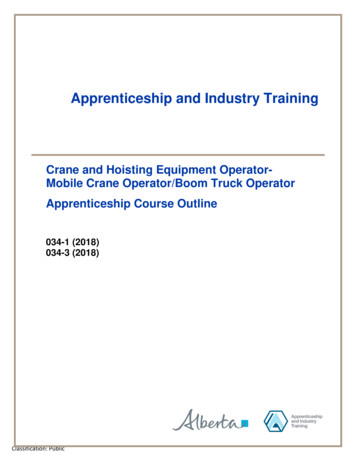
OPERATIONMACHINE TLV 4300 330510 (8 98)Vacuum Hose Support ArmVacuum FanHopperRoll Over Protection SystemSeat BeltOperator SeatEngineVacuum Head (Option)Vacuum Adjustment Knob (Option)Vacuum HoseRear View MirrorsVacuum Wand HandleVacuum Hose Support Arm Adjustment Knob7
OPERATIONCONTROL PANEL SYMBOLSThese symbols identify controls and displays onthe machine:OnOffStartFast Vacuum Fan / Engine SpeedVacuum FanMedium Vacuum Fan / Engine SpeedEngine Oil PressureIdle Engine SpeedEngine Water TemperatureCircuit breaker #1VoltmeterCircuit breaker #2Parking BrakeCircuit breaker #3Operating LightsCircuit breaker #4Glow Plug (Preheat)Circuit breaker #5Hazard Light (Option)Circuit breaker #6Signal Light (Option)Circuit breaker 7Vacuum Head Control (Option)Circuit breaker 8Vacuum Hose Height AdjustmentHornWater Dust Control (Option)8ATLV 4300 330510 (12 01)
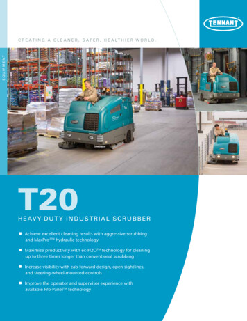
OPERATIONCONTROLS AND .M.N.O.P.ATLV 4300 330510 (9 00)Steering WheelSteering Wheel Tilt LeverIgnition SwitchTurn Signal Lever (Option)Vacuum Fan SwitchVacuum Head Switch (Option)Fuel Level GaugeHourmeterEngine Temperature LightEngine Oil Pressure LightCharging System LightThermo Sentryt Warning Light (Option)Vacant (No Reading)Hydraulic Filter Bypass LightParking Brake Light (Option)Glow Plug Light9
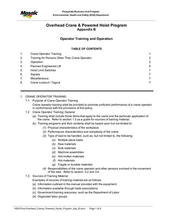
OPERATIONJAFEIDGCHBKA.B.C.D.E.F.G.H.I.J.K.10Horn ButtonThrottle LeverWork Lights Switch (Option)Operating/Hazard Lights Switch (Option)Operating Lights SwitchWater Dust Control Switch (Option)Directional PedalBrake PedalsParking Brake PedalsCircuit Breaker PanelWindshield Wiper Knob (Option)ATLV 4300 330510 (12 01)
OPERATIONOPERATION OF CONTROLSSTEERING WHEELThe steering wheel controls the machine’sdirection. The machine is very responsive to thesteering wheel movements.Left: Turn the steering wheel to the left.Right: Turn the steering wheel to the right.STEERING WHEEL TILT LEVERThe steering wheel tilt lever is used to adjust theangle of the steering wheel. To tilt the steeringwheel, pull the lever straight out. Position thesteering wheel at the desired angle, then releasethe lever.IGNITION SWITCHThe ignition switch starts and stops the enginewith a key.FOR SAFETY: When starting machine,keep foot on brake and directional pedalin neutral.Preheat: Turn the key counter-clockwise. Theglow plug light will come on. When the glow pluglight goes out, usually in 5 to 30 secondsdepending on the weather conditions, the engineis ready to start.Start: Turn the key all the way clockwise. Releasethe key as soon as the engine starts.Stop: Turn the key counter-clockwise.ATLV 4300 330510 (8 98)11
OPERATIONTURN SIGNAL LEVER (OPTION)The turn signal lever is used to activate the turnsignal lights when turning.Right Signal On: Push the lever up.Left Signal On: Push the lever all the way down.Signal Off: Return the lever to the middle position.Four Way Flashers: Pull out the knob.VACUUM FAN SWITCHThe vacuum fan switch controls the machine’svacuum fan.Vacuum On: Press the top of the switch.Vacuum Off: Press the bottom of the switch.VACUUM HEAD SWITCH (OPTION)The vacuum head switch raises and lowers thevacuum head that mounts under the front end ofthe machine.Raise: Press the bottom of the switch.Lower: Press the top of the switch12ATLV 4300 330510 (8 98)
OPERATIONFUEL LEVEL GAUGEThe fuel level gauge indicates how much fuel isleft in the fuel tank.Note: Do not let the fuel tank empty completely.Air can enter the fuel system, and it may needbleeding before the next engine start.HOURMETERThe hourmeter records the number of hours themachine has been operated. The hourmeterdisplays the number of hours in tenths of an hour.Use this information to determine machinemaintenance intervals.ENGINE TEMPERATURE LIGHTThe engine temperature light comes on when thetemperature of the engine coolant is more than113 C (235 F). If the light comes on, stopoperating the machine. Locate the problem andhave it corrected. See the MAINTENANCEsection of this manual.ATLV 4300 330510 (9 99)13
OPERATIONENGINE OIL PRESSURE LIGHTThe engine oil pressure light comes on when theengine oil pressure falls below 40 kPa (5psi). Ifthe light comes on, stop operating the machine.Locate the problem, and have it corrected.CHARGING SYSTEM LIGHTThe charging system light comes on when thealternator is not operating within normal range;13.5 to 14.5 V. If the light comes on, stopoperating the machine. Locate the problem, andhave it corrected.THERMO SENTRY WARNING LIGHT (OPTION)The Thermo Sentry warning light comes on whenthe Thermo Sentry senses that there is excessiveheat in the hopper, possibly from a fire. TheThermo Sentry will also shut off the vacuum fan.If this happens, stop the machine and eliminatethe source of heat. Allow the sensor to cool, and itwill reset automatically.14ATLV 4300 330510 (8 98)
OPERATIONHYDRAULIC FILTER BYPASS LIGHTThe hydraulic filter bypass light comes on whenthe hydraulic filter is clogged. If this light comeson, have the hydraulic filter and hydraulic fluidchanged as soon as possible.PARKING BRAKE LIGHT (OPTION)The parking brake light comes on when theparking brake pedals are engaged. To turn off thelight, simply disengage the parking brake pedalsbefore moving.GLOW PLUG LIGHTThe glow plug light comes on when the ignitionswitch is turned counterclockwise to the GlowPlug position. The light will go out when theengine is ready to start.ATLV 4300 330510 (9 00)15
OPERATIONOPERATING LIGHTS SWITCHThe operating lights switch powers on and off theheadlights and taillights.On: Press the switch to the forward position.Off: Press the switch to the middle position.OPERATING/HAZARD LIGHTS SWITCH(OPTION)The operating/hazard lights switch powers on andoff the headlights, taillights and the hazard lightoption.Operating lights on: Press the switch to theforward position.Operating/Hazard lights on: Press the switch tothe back position.Off: Press the switch to the middle position.WORKLIGHT SWITCH (OPTION)The worklight switch controls the worklights.Worklights on: Press the switch to the forwardposition.Worklights off: Press the switch to the backposition.WATER DUST CONTROL SWITCH (OPTION)The water dust control switch powers on and offthe water dust control located in the debriscanister.On: Press the switch to the forward position. Theswitch will light up.Off: Press the switch to the back position. Thelight in the switch will turn off.16ATLV 4300 330510 (12 01)
OPERATIONHORN BUTTONThe horn button controls the horn.Sound: Push buttonTHROTTLE LEVERThe throttle lever controls the engine speedand vacuum fan power.Move the throttle lever forward until desiredengine speed/vacuum power is reached .Idle: Pull the lever backward.Normal Operating Speed / Vac Power: Push thelever to the middle Speed 1 position.Max Operating Speed/ Vac Power: Push the leverall the way forward to the Speed 2 position.SEAT BELTThe seat belt holds the operator securely in theoperator’s seat.Connect seat belt: Insert the male end of the seatbelt into the female end until they click securelyinto place.Disconnect seat belt: Press the button on thefemale end buckle and pull the ends apart.ATLV 4300 330510 (12 01)17
OPERATIONFUSESThe fuse is a one-time protection device designedto stop the flow of current in the event of a circuitoverload. Never substitute higher value fusesthan specified.The fuse is located behind the circuit breakerpanel.FuseRatingCircuit ProtectedFU-130 AGlow plugCIRCUIT BREAKERSThe circuit breakers are resettable electricalcircuit protection devices. Their design stops theflow of current in the event of a circuit overload.Once a circuit breaker is tripped, it must be resetmanually. Press the reset button after the breakerhas cooled down.If the overload that caused the circuit breaker totrip is still there, the circuit breaker will continue tostop current flow until the problem is corrected.The circuit breaker panel is located above the footpedalsThe chart lists the circuit breakers and theelectrical components they protect.BreakerRatingCircuit ProtectedCB-115 AAccessory/ Vac/ HydCB-215 AHornCB 315 AWork LightsCB-415 AOperating LightsCB-515 ABrake/ Turn signalsBack Up alarmCB-615 AOpen Cab Acc.CB-715 AOptionsCB-815 AOptions18ATLV 4300 330510 (9 99)
OPERATIONBRAKE PEDALSThe brake pedals slow down and stop themachine. Each pedal operates its own rear brakeindependently.Stop Machine: Take your foot off the directionalpedal, and let it return to the neutral position. Stepon both of the brake pedals.The brake pedals run each brake independently.The operator can use the brakes to remove themachine from a stuck position. If a tire is slippingor unable to make contact with the drivingsurface, simply press on that tire’s brake pedalwhile slowly pressing on the propelling pedal. Thiswill divert the power to the opposite tire, helping tomove the machine from its position.PARKING BRAKE PEDALSThe parking brake pedals set and release thebrake pedals.Set parking brakes: While pressing both brakepedals down as far as they will go, set the parkingbrakes by pressing the parking brake pedals withthe toe portion of your foot. The parking brakelight (option) will turn on while the parking brake isset. Always set both parking brake pedals whenparking the machine.Release parking brakes: Press on the brakepedals to unlock the parking brake pedals.ATLV 4300 330510 (8 98)19
OPERATIONDIRECTIONAL PEDALThe directional pedal controls the direction oftravel and the propelling speed of the machine.You can change the speed of the machine withthe pressure of your foot on the pedal; the harderyou press the pedal, the faster the machinetravels.Forward: Press the top of the directional pedalwith the toe of your foot.Reverse: Press the bottom of the pedal down withthe heel of the foot.Neutral: Take your foot off the directional pedaland it will return to the Neutral position.Note: There is a pedal angle adjustment pinbehind the propelling pedal. Remove the pin, setthe pedal at the desired angle for operation andreinsert the pin.20ATLV 4300 330510 (9 99)
OPERATIONOPERATOR SEATThe operator seat is a fixed back style with aforward backward adjustment.Adjust: Push the lever to the left, slide the seatbackward or forward to the desired position andrelease the lever.DELUXE SUSPENSION SEAT (OPTION)The deluxe suspension seat has threeadjustments. The adjustments are for theoperator’s weight, backrest angle and the front torear seat position.The operator’s weight adjustment lever controlsthe seat weight adjustment. The lever has threepositions: lightweight, middleweight andheavyweight.Adjust: Pull the lever up for the lightweightposition, move the lever to the middle position formiddleweight, and push the lever down for theheavyweight position.The backrest angle knob adjusts the backrestangle.Adjust: Turn the angle knob clockwise to decreasethe angle of the backrest. Turn the knobcounterclockwise to increase the angle of thebackrest.The front to rear position lever adjusts the seatposition.Adjust: Pull the lever out, slide the seat backwardor forward to the desired position and release thelever.ATLV 4300 330510 (8 98)21
OPERATIONVACUUM WAND HANDLEThe vacuum wand handle is used to control theintake end of the vacuum hose. The vacuumwand can be positioned on either side of themachine. The vacuum wand handle is adjustable,and can be positioned at any height on thevacuum wand.To adjust the vacuum wand handle: Loosen thescrews on either end of the wand handle, positionthe handle to the desired height, and tighten thescrews.To remove the vacuum hose from the optionalvacuum head: Push forward and up on thevacuum wand handle, and lift the vacuum hose offthe vacuum head.22ATLV 4300 330510 (8 98)
OPERATIONVACUUM HOSE SUPPORT ARMThe vacuum hose support arm is a gas cylindersupported arm that holds the vacuum hose at anyadjustable height above the ground.To adjust arm height: Turn the adjustment knobclockwise or counterclockwise to adjust the gascylinders, and raise or lower hose to preferredheight.Raise vacuum hose: Turn knob counter clockwise.Lower vacuum hose: Turn knob clockwise.Note: After turning the adjustment knob, pull thevacuum wand support arm down and let it springup to determine the effect of the adjustment.Adjust further if necessary.ATLV 4300 330510 (8 28)23
OPERATIONVACUUM HEAD ADJUSTMENT KNOB(OPTION)The vacuum head adjustment knob controls thedown stop for the ground clearance height on thelowered vacuum head.To set the clearance height: Lower the vacuumhead as low as it will drop with vacuum headcontrol switch.Raise vacuum head adjustment: Turn the knobcounterclockwise.Lower vacuum head adjustment: Turn the knobclockwise.Note: When adjusted properly, the rear skirt of thevacuum head should be rolled out about 13mm(.50 in) in the rear on a flat hard surface.REAR VIEW MIRRORSThe rear view mirrors are used by the machineoperator to keep an eye on the area behind themachine that is not in the standard field of vision.To adjust mirrors: Sit in the operator’s seat. Moveeach mirror until it is properly adjusted for theindividual operator’s rear viewing area.HOPPER TILT BRACKETThe hopper tilt bracket is located under the rear ofthe hopper. The bracket will hold the hopper inplace when it is lowered into the bag tyingposition. The bracket will “snap” and release thehopper when it is pushed down into the debrisremoval position.FOR SAFETY: When Using Machine, DoNot Move Machine With Hopper Open.24ATLV 4300 330510 (8 98)
OPERATIONLATCHESThe engine door is secured with a latch.Open: Press on the raised part of the latch.Close: Close the door and press on the flat end ofthe latch.Machines with serial numbers below #001070have a vacuum bag quick release strap securedwith a latch and cotter pin.Open: Remove cotter pin and lift up on the raisedpart of the latch.Close: Press on the raised part of the latch untilthe strap is secured. Replace the cotter pin.The hopper top is secured with two latches.Open: Lift up on the bottom tab of the latch, andraise the latch up out of the lower holding bracket.Close: Check that there is no debris on the outeredge of the hopper. Close the hopper lid securely.Place the top of the latch in the slotted bracket onthe hopper bottom. Push down on the latch until itsnaps into place.The panel filter option door is secured with twolatches.Open: Pull the rear of the latch away form thefilter housing, and then unhooking the front of thelatch from the keeper.Close: Hook the front of the latch onto the keeperand push latch towards the filter housing until itsnaps into place.ATLV 4300 330510 (3 01)25
OPERATIONMachines with serial numbers 003017 and abovehave a hydraulic cooler that opens for cleaning. Itis located behind the Radiator inlet screen. Pullout the pins to remove the screen to access.Open: Pull up on the latch.Close: Push the latch into the hole, then push thelatch down.HOW THE MACHINE WORKSThe steering wheel controls the direction ofmachine travel. The directional pedal controls theforward/reverse direction and the machine speed.The brake pedal slows and stops the machine.The machine vacuums large debris from variousterrain. The vacuum hose is controlled by theoperator. The vacuum takes debris in through thehose and transfers the debris into the hopper.The machine has an optional Vacuum Head, andan optional wand with a 4572 mm (15ft.)extension.When vacuuming is finished, check the vacuumhose, clean the hopper fan screen and empty thehopper.PRE-OPERATION CHECKLIST- Check under the machine for leaks (fuel, oil,coolant).26ATLV 4300 330510 (4 09)
OPERATION- Empty the engine air filter dust cap.- Check the engine oil level.- Check the fuel level.- Check the brakes and steering for properoperation.ATLV 4300 330510 (4 09)27
OPERATION- Check the coolant level in the overflowreservoir.- Check the radiator inlet screen for debris,and clean if required.- Check the vacuum bag for debris, andempty if required.- Check the water dust control tank, fill ifrequired. (Option)28ATLV 4300 330510 (4 09)
OPERATION- Check the vacuum fan screen for debris,and gently clean with a broom if required.- Check the hopper, empty if required.- Check the vacuum hose for damage, cracksand lodged debris.ATLV 4300 330510 (3 99)29
OPERATION- Check the vacuum hose support arm forproper adjustment.- Check the vacuum wand handle for properadjustment.- Check the vacuum head skirts for wear.(Option)30ATLV 4300 330510 (8 98)
OPERATIONSTARTING THE MACHINE1. Check the directional pedal to make sure itis in the middle neutral position.2. Sit in the operator’s seat with your foot onthe brake pedal or with the parking brakeset.3. Put on the seat belt.ATLV 4300 330510 (9 99)31
OPER
ATLV 4300 *330510* 330510 Rev. 21 (8-2019) North America / International Litter Vacuum Operator Manual TennantTrue Parts For latest parts manual or other language operator manual, visit: