Transcription
April 201335SECTION 33SYSTEM COMPONENTSAll components or materials utilized in an on-site sewage disposal system must meet thespecifications in this guideline and be approved for use by Nova Scotia Environment. If aproduct, component or material is not currently listed in this guideline, it must be approvedNova Scotia Environment prior to use.3.1SEPTIC TANKS, HOLDING TANKS AND PUMP OR SIPHON CHAMBERSThe following requirements apply to any tank that is selected or designed for use as a septictank, holding tank, pump and/or siphon chambers:1. The tank must be designed to carry a minimum of 600 mm of earth cover.2. The top of the tank must be marked to indicate the maximum permissible depth ofbury.3. Septic and holding tanks must conform to Standard CAN/CSA-B66-00 or the latestrevision. Metal tanks are not permitted for use as a septic tank, pump or siphonchamber; acceptable materials are reinforced concrete, fibreglass, or polyethylene.Holding tanks, if located above ground, must be non-corrodible. For undergroundholding tanks, metal is not permitted.4. Where a tank is installed in an area where high groundwater levels may occur, themanufacturer shall include instructions to prevent flotation of the tank.5. All tanks must be watertight.6. Where a riser is required, it shall be watertight firmly attached to the tank with a permanent watertight seal designed to resist frost action.7. The cover of a tank or a riser shall be watertight secured to prevent unauthorized access and injury.8. The manufacturer of a prefabricated tank shall provide to the installer instructions forassembly and installation of the tank. The instructions shall have been submitted forreview by the Department, to assure that they address the requirements of theseGuidelines.9. A sectional pre-fabricated tank may be assembled on site, provided that themanufacturer's instructions are followed to produce a watertight tank.10. Where a tank is manufactured from concrete; the bung hole must be permanentlyclosed in a watertight manner.11. A tank may be constructed on-site if it conforms to applicable requirements of thissection and has been designed by a Level 1 Qualified Person12. It is recommended that the tank be tested on site after assembly, for water tightness(see Section 6.4 for a recommended testing procedure).
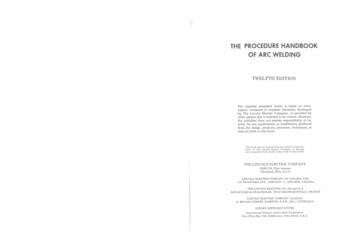
April 20133.1.1 Septic Tanks36Any septic tank is required to meet the following specifications: (Figure 3A)1. All tanks must conform to the latest edition of Standard CAN/CSA-B66-00 or thelatest revision, published by the Canadian Standards Association.2. It must include a watertight access for purposes of maintenance, inspection, andpump-out.3. Septic tanks for dwellings must have a total capacity not less than that stated in Table3.1. For larger systems the minimum capacity should be: For average daily flows up to 9000 l/day: Vtank(1) 2QWhere: Q - average daily flow in litresVtank - total tank volume in litres For average daily flows 9000 l/day or more: Vtank(2) 9000 QWhere: Q - average daily flow in litresVtank - total tank volume in litresVtank may be achieved by one or multiple tanks in series or parallel;design volume represents total minimum capacity.The minimum required septic tank capacity is 2800 L. Septic tank sizes larger than therequired minimum may reduce problems and extend the life of an on-site system.TABLE 3.1MINIMUM CAPACITY OF SEPTIC TANKS FOR DWELLINGSNumber of BedroomsMinimumLiquid Capacity (litres)Up to345280033004500 When selecting a tank, the depth of bury must be considered. If it is greater than 600mm, the tank shall be stamped to indicate that it has been designed to withstand burial tothe required depth.4. These values must be increased by 20 percent where a garbage grinder is used.5. Access to a tank must be provided by a single opening at the outlet of the tank toprovide effluent filter access, but two openings—over the inlet and outlet—arerecommended for easier service. The dimension of any opening shall meet CSArequirements.6. A riser shall be extended to the ground surface and the cover fitted with a suitablelocking mechanism. The area around the riser should be graded to divert surface wateraway from the riser.7. The top of a septic tank must be at least 150 mm and not more than 1500 mm belowfinished grade or as specified by the manufacturer’s instructions.8. Where a siphon chamber is included in the system, it may be an integral part of theseptic tank, or be a separate structure.
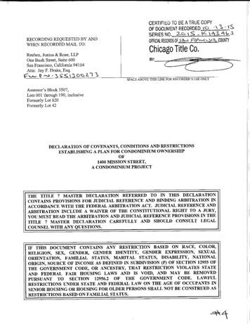
April 2013379. The manufacturer's instructions shall describe how inlet and outlet connections to thetank are to be made in a watertight and structurally secure manner.10. If a sewage lift pump discharges to a septic tank The volume of the septic tank must be at least 4500 L The discharge per cycle from the lift pump must not exceed 115 L The discharge rate from the lift pump must not exceed 45 L/min The discharge line from the lift pump must be fitted with a flow control valve. A two compartment tank is recommended. Two single tanks in series can be used as a substitute for a two compartmenttank.11. Except as indicated in Section 3.1.1 #10 above, two compartment tanks are notcurrently required, but they are recommended because they reduce solids carry-overto the disposal field.Where a two compartment tank is used: the final compartment should be approximately one-third of the total volume the interconnecting port should be about 2/3 of the liquid depth from thebottom of the tank.12. All residential septic tanks are required to have a septic tank effluent filter that meetsNSF Standard 46 (components of wastewater treatment systems) and has easy accessat finished grade over the outlet of the septic tank for filter maintenance. A properlyfitted effluent filter will decrease the risk of solids entering the disposal field andprolong life of the system.3.1.2Holding Tanks1. A holding tank must conform to the latest edition of Standard CAN/CSA-B66-00 orthe latest revision, published by the Canadian standards Association. (Figure 3.B).Also refer to testing specifications in Section 6.4.2. The capacity of a holding tank for a single unit residential dwelling shall not be lessthan 4500 L. Refer to Table 4.13 for selection.3. A holding tank shall be equipped with an audible and visible high level alarm.4. A holding tank shall be installed so that its locked riser cover is exposed at or abovefinished grade, and the area around the cover must be graded to divert surface water.5. All openings, including the riser, must meet CSA requirements.6. The installation, operation and maintenance of the holding tank shall be in accordancewith minimum standards and policies. Refer to Subsection 4.10 for further detailsand selection of holding tank.7. A below ground tank shall be constructed of a non-metallic material.8. A holding tank may be utilized for above ground services provided: the tank is constructed of non-corrodible material secondary containment is supplied (dykes, berms, etc) adequate weatherproofing is provided to prevent freezing in the tank or lines the tank is supplied with adequate hold down and support systems the inlet shall be on the top of the tank and the inlet line shall be self-draining drain valves are locked when not in service or security in the form of a fence isprovided the tank vent is equipped with an odor control device or is extendedsufficiently above grade to eliminate odors at ground level tank to be installed according to existing Nova Scotia Environment policies,regulations and operational bulletins
FIGURE 3.ASEPTIC TANKGround surfaceDo not install septic tank, grease ,siphon or pump chamber underpermanent structures such as porch, etc.Max. 150 mm *Riser for deep installationsGround surfaceCoverGENERAL:1. A septic tank for a single family will generallyrequire pumping every 3 to 5 years, but should beinspected yearly.2. Septic tank for commercial applications should beinspected every 6 months.3. Septic tank should be pumped when the sludgeaccumulates to a level approximately 450 mmbelow the bottom of the outlet fitting, or if thescum level builds to within 75 mm of the bottomof the baffle or tee outlet.4. Septic tank must be pumped by a registered septictank cleaner.5. Tank, pump/siphon chambers, covers and risers mustbe sealed completely watertight. Surface drainageshould be directed away from the tank or chamber.6. If the invert of the tank or chamber will be installedbelow groundwater level it shall be secured in placeto prevent flotation7. DO NOT ENTER SEPTIC TANK, PUMPCHAMBER OR GREASE TRAP!TEST FOR TANKS AND PUMP/SIPHON CHAMBERSThe test for septic tank and siphon/pump chamber water tightness, ifrequired, should be conducted after installation and before backfill.Covers must be secured to preventunathorized entry.1. If tank or chamber is installed below ground water level, firstremove any water from the tank. Tank must be left for 30 minutesand checked for any visible leaks. Prior to test tank must be securedin place to prevent flotation.InflowMin. 25 mmVolume 10 % of theworking capacityScum Layer25% to 40% ofliquid depth75 mm to125 mmOutflow2. If the tank or chamber is installed above ground water table, tankmust be filled with water to its outlet, left for 30 minutes andchecked for any visible leaksAny leaks must be repaired and test repeated until all leaks areeliminated.Prior to test confirm with manufacturer that tank will withstand ahydrostatic pressure.Liquid depthMin. 900 mmSee Section 6.4 of the Guidelines for further information.Required effluent filterSludgeOptional barrier wall used in2 compartment septic tankBedding as per manufacturers instructionBedrockDimensions shown on this sketch are for illustration only. Design of the tankmust follow latest edition of standard CAN/CSA - B66-M00 or latest revision* Riser may extend to surface provided the cover isfitted with a suitable locking mechanism.
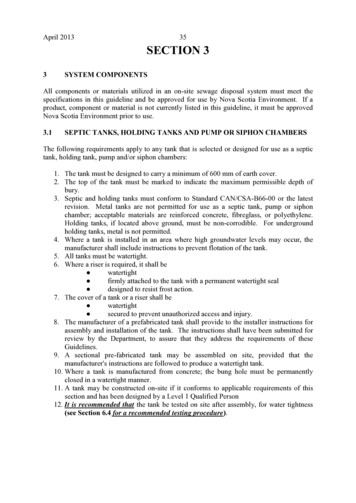
April 2013399. It is recommended that the holding tank be tested on site after assembly, for watertightness (see Section 6.4 for a recommended testing procedure).3.1.3Pump and Siphon ChambersThe pump or siphon chamber discharge capacity must be sized to distribute effluent over theentire disposal field during each dose. This allows utilization of the entire field andminimizes the possibility of breakout of effluent in a localized area. Periodic dosing alsoallows the infiltrative surface to drain between doses. These cycles of alterative dosing andresting may maintain higher infiltration rates in the clogging mat and thus extend the life ofthe system.The normal dosing frequency should be a minimum of two times per day for a system that isselected. More frequent lower volume doses are recommended. The discharge volume mustbe large enough to flood the entire distribution pipe. Unless the level 1 or 2 qualified personspecifically selects the pump to be used, it is the installers responsibility to ensure that thepump has the proper capacity of achieving equal distribution throughout the field.A typical pump chamber is shown in Figure 3.C and shall conform to Canadian StandardsAssociation specification CAN/CSA-B66-00 or the latest revision.Requirements for a pump chamber include:1. The liquid capacity of the chamber shall provide storage equal to one days flow.2. The chamber shall be equipped with an audible and visible high level alarm, levelcontrols, and other accessories required to assure its effective and reliable operation.3. If the top of the tank is more than 150 mm below finished grade, a riser must beprovided to extend to within 150 mm of finished grade. Extending the riser to groundsurface is recommended and must include a cover and locking mechanism.4. The dimension of any opening shall meet CSA requirements.5. The elevation of the tank shall be such that any horizontal seam is located above thehighest seasonal groundwater table6. The high water alarm level must be below the level of the horizontal seam.7. It is recommended that the pump chamber be tested on site after assembly, for watertightness (see Section 6.4 for a recommended testing procedure).A siphon chamber shall conform to Canadian Standards Association specificationCAN/CSA-B66-00 or the latest revision. A sample of a siphon chamber is detailed inFigure 3.E and 3.F.Requirements for a siphon chamber include:1. If the top of the tank is more than 150 mm below finished grade, a riser must beprovided to extend to within 150 mm of finished grade. Extending the riser to groundsurface is recommended and must include a cover and locking mechanism.2. The dimension of any opening shall meet CSA requirements.3. It is recommended that the pump chamber be tested on site after assembly, for watertightness (see Section 6.4 for a recommended testing procedure)
FIGURE 3.BBell for audible alarm may be switched offALARM DEVICEAlarm should sound whenholding tank is 75% full.Light to give a visualalarm remains on afterbell is switched off anduntil tank is emptiedCover with lock toprevent unauthorizedaccessExtension with watertight connection to tankAll connections must be made water tightWatertight if below watertableNOTE:If effluent is pumped totank, an appropriate ventshould be installed.Alarm float controlFasten both sides of the holdingtank to prevent frost uplifting.If riser is provided it also must befastened to prevent frost upliftingPlug all openingsMake a watertightconnectionNOTE:Tank must be made watertight and it isrecommended that the tank be tested for leaksbefore it is placed in operation. See section6.4 for a recommended testing procedure.Dimensions shown on this drawingare for illustration only. Design ofthe tank must follow latest edition ofstandard CAN/CSA - B66-00HOLDINGTANK
FIGURE 3.CPump installationSiphon Breaker is required on allpump systems with pump chamber atlower elevation than finished gradeover disposal field.The siphon breaker does not protectagainst backflow into the pumpchamber, septic tank and possibly thehome, should surface or ground waterflood the system to a level above thebottom of the “breaker”. Lot gradingand interceptor ditches will reduce thepossibility of this occuring. A checkvalve can also be installed on the linebetween the tank and the pumpchamberAlarm inside homeRelay in water-proof enclosure orhouseCover must be secured toprevent unathorized accessSeal if below watertableHanger pipe forpump removalReserve capacity afteralarm soundsQuick disconnectslider couplerFromseptic tankTYPICAL DETAIL OF FORCEMAINCONNECTION TO DISPOSAL FIELD“SIPHON BREAKER”Minimum 300 mm ofsoil cover3 mm air hole top ofpipe450 mm minimumMust be protectedfrom freezingFinished grade300 to 450 mm150mm75 mm crushed rock andgeotextile over entire pipePerforated distributionpipeTo disposal fieldPressure pipe frompump chamberAll joints must be watertightApproved pump chamberPump alarm levelNOTES:1. The pump chamber must be watertight and surface water must be diverted away from the pump chamber.2. The pump intake should be kept above the floor at the distance recommended by manufacturer .(Frequently 150 mm or more).3. The start level control should be set to deliver the required dosage plus an allowance for backflow fromthe discharge line (if backflow is used for frost protection).4. The alarm system and the pump must be on separate circuits.5. All electrical connection are to be made outside the pump chamber and must comply with appropriateelectrical code and safety regulations.6. Pump must be suitable for submerged sewage operation.7. Level control floats to be non clogging.8. All pipe joints must be pressure resistant.9. The pump stop level should be at leastVolume of 1m pipe section100 mm above the impeller of the pumpDiameter (mm) Volume(l/m)Dosing volumePump on levelStartPump off levelStopLevel control float(switch)FROST PROTECTION:Following may be employed to protect pressure pipe from freezing:PIPE INSULATION1. Allowing the effluent to drain back through the pump and into the pumpchamber by removing the check valve. This can only be done if design of thepump allows it. Check with manufacturer prior to removing check valve.2. Installation of check valve at the pump with a bleeder hole just ahead of it. Thiswould prevent effluent from flowing back through the pump and still allow theline to drain.3. Installation of check valve and pipe protection such as:a. Sufficient soil cover over the line. (Usually 1.5 m)b. Insulation of the line.c. The use of heater tapePipe must be installed to prevent any sagging.SurfaceUsually 1.5 m300150600Insulation. Usually 25 mm foreach 300 mm of soil cover lessthan 1.5 m.HI-60 Styrofoam .706.207.128.20
June 2013423.2BUILDING SEWERS AND EFFLUENT LINESA building sewer for a single unit dwelling, which is defined as the part of the buildingdrainage system carrying sewage that extends from the septic tank or public sewer to a pointone metre out from the foundation wall, shall be a 100 mm diameter pipe, conforming toCanadian Standards Association specification CAN/CSA B-182.1. Cleanouts shall beprovided at intervals of not more than 30 m, if the length of the building sewer exceeds 60 m.A building sewer shall be laid at a slope of not less than 2 percent.An effluent pipe for a single unit dwelling, which is defined in the Regulations as a nonperforated pipe used in a system to transfer effluent from a septic tank, pump or siphonchamber to a disposal field shall be a 75 or 100 mm diameter pipe for gravity flow systemsand must conform to Canadian Standards Association specification CAN/CSA B-182.1.An effluent pipe for a gravity flow system shall be laid at a slope of not less than 1 percent.3.3DISTRIBUTION SYSTEM3.3.1Crushed Rock or GravelCrushed rock shall be: cleaned, washed, and screened, free of soft or friable material, 98% (by weight) of rock or gravel shall pass a 35 mm screen and 98% (by weight) of the rock or gravel shall be retained on a 12 mm screen.3.3.2Imported Sand FillThe following requirements apply to: the buffer in a distribution system, i.e., C2 and raised C2 the construction of all above ground systems, i.e., a C3 and a moundThis material shall: if it is a naturally occurring or manufactured sand or recycled crushed glass, have apermeability, as placed on site, between 0.00003 and 0.0005 m/sec, as determined bythe falling head permeability test (Appendix B) and have a maximum particle sizecorresponding to the appropriate ASTM-33 or CSA A23.1 specification for fineaggregate. when designing or selecting a system with a specified fill permeability within theacceptable range of 0.00003 and 0.0005 m/sec; the Qualified Person shall ensure thatfill with the specified permeability range required by the selection or design is used insystem construction.3.3.3 Filter Sand and Sloping Sand Filter MaterialThe following requirements apply to: The layer of sand (filter sand) installed under the crushed rock in all systems The sand used to construct a sloping sand filter
June 201343This material shall: be a manufactured sand that meets the current ASTM-33 or CSA A23.1specifications; or be a naturally occurring or manufactured sand or recycled crushed glass having apermeability, as placed on site, between 0.0001 and 0.0005 m/second as determinedby the falling head permeability test (Appendix B) and have a maximum particle sizecorresponding to the appropriate ASTM-33 or CSA A23.1 specification for fineaggregate.3.3.4 Safety Considerations for use of Recycled Crushed GlassWhen using recycled crushed glass as a replacement for imported or filter sand in an on-sitesewage disposal system, the QP must ensure its permeability meets the requirements outlinedin Sections 3.3.2 & 3.3.3 for its intended use.Qualified persons and installers intending on using the crushed glass in on-site sewagedisposal systems in Nova Scotia shall be knowledgeable of the material safety informationprovided by the manufacturer.3.3.5Barrier Material (Geotextile)Barrier material is required in disposal fields to prevent silt in the covering soil from washingor falling into the crushed rock distribution trench.The barrier material shall: be a non-degradable man-made fibre such as polyester or polypropylene;have an opening size less than 700 microns; andhave a permeability greater than 0.001 m/sec.This specification will normally be met with a light weight (50 g/sq. m or more) non-woven(i.e. felted, needle punched or heat bonded fibre) fabric or proprietary geotextile. The abilityto stretch and deform is perhaps of more importance than tensile strength. It should be notedthat typical woven geotextiles of ribboned film have insufficient permeability and porosityfor adequate aeration of the disposal field and for upward permeation of effluent in highwater table conditions.3.4EFFLUENT DISTRIBUTION PIPE3.4.1GeneralUniform distribution of septic tank effluent over the entire area of the disposal field is criticalfor the performance and the long life of the system: uneven distribution can result inprogressive clogging of the soil interface, or inadequate treatment in very permeable soils.Periodic dosing of the effluent, with resting periods between doses, also improves theperformance of a system.Effluent distribution can be accomplished by one of two basic methods:
April 201344 a gravity distribution system, in which effluent flows from a septic tank to a disposalfield because the water level in the tank is higher than the level of the field, or a pressure system, in which a pump or siphon is used to create pressure that will forceeffluent throughout the distribution systemPipe and pipe joint fittings used in a disposal system must be selected to provide: 3.4.2durabilityresistance to crushing due to surface loadingresistance to differential settlement of soils and system components.Gravity Distribution PipesGravity pipes in an on-site system shall:1. be watertight, except for pipes in a disposal field;2. have an internal diameter not less than 75 mm; and3. have a slope of 50 to 100 mm / 30 m.Distribution pipes shall conform with Canadian Standards Association standard CSA B182.1with a hole spacing as described and shown in diagram 3.D. The pipe shall be of PVC orABS plastic, unless an alternative material with equal or better properties is approved NovaScotia Environment.The pipe shall be perforated with 13 mm holes: in the invert, at intervals of 3 to 4 m; andat 60 degrees to the invert, at intervals of 1 m or less.The invert holes are intended to disperse smaller flows; the side holes will disperse largerflows.3.4.3Pipe Used In a Pressurized SystemA pressurized system is more effective than a gravity system as it provides both uniformdistribution and periodic dosing of the disposal field. The disadvantage of a pressurizedsystem is the higher capital cost and the extra maintenance requirements associated with thepump or siphon. Pressurizing using a pump or siphon is required: where an end fed field is longer than 30 m or a center fed field is longer than 60m;where the natural ground slope is not uniform and a gravity system might concentrateeffluent at one on more weak spots in the field;for all C3 and Mound fields; orfor any system where the disposal field is at a higher elevation than the septic tank.Where a pump or siphon is required, the solid pipe from the pump or siphon chamber to thedisposal field must have a minimum diameter as specified by the pump or siphonmanufacturer but shall not be less than 30 mm. For a pump system this line shall beequivalent to the Canadian Plumbing Code requirements for water pipe (CSA B137 Series)
April 201345so that it can withstand the pressure exerted by the pump. Lower pressures are generated by asiphon and solid pipe meeting CSA B182.1 with glued joints should be acceptable. Allpumped systems should be connected to the disposal field using a “siphon breaker” as shownin Figure 3.C.For any system selected to serve a single family home using a Mound or C3 field, solid 75 or100 mm pipe with holes drilled as outlined in Subsections 4.7.4 and 4.8.4 must be used.For any other system selected to serve a single family home using a pump or siphon, theperforated pipe in the distribution field can be similar to gravity distribution pipe (Subsection3.4.2) only all joints must be glued and a 13 mm hole drilled in the top of the pipe 150 mmfrom the end cap(s). In addition the distribution piping must be placed such that there isno slope on the piping in the distribution trench.For systems serving more than 1500 l/day (designed by a QP1), the pipe diameter, and holespacing must be calculated, based on the system hydraulics, in an effort to provide uniformdistribution throughout the disposal field. In a designed system the minimum acceptable pipediameter is 35 mm.Freezing of the pressure line is a potential problem if it does not empty after every dischargeand it is not insulated. Figure 3.C. lists several steps that can be taken to protect the pressureline from freezing.3.5PUMPS AND SIPHONS3.5.1GeneralA pressure distribution system may be fed by a pump or a siphon.selection of these devices include: Considerations inSiphons do not require a power source or involve moving partsA siphon will operate more effectively if the available elevation difference betweenthe siphon discharge point and the disposal field distribution pipe is 1 m or more. Fora normal siphon installation this is equivalent to 2m in total from the tank outlet to thedisposal field.Siphons can be selected for distances up to 30 m and no less than 0.5m drop from thedischarge to the disposal field unless indicated otherwise in the manufacturer'sinformation; in which case, the syphon shall be installed in accordance with themanufacturer's instruction.Siphons can be designed for distances greater than 30 m.When a pressure distribution system is required, the siphon or pump should be designed toflood the disposal field a minimum of twice per day. More frequent lower volume doses arerecommended - ensure the entire pipe is completely filled and under pressure.Where a siphon is required, the siphon must follow a standard design established, approvedor adopted by the Department, or shall be designed by a Level I Qualified Person.
April 20133.5.1.a Hydraulic Characteristics46When choosing a pump, consideration should be given to the following: The difference in elevation between the pump and the distribution pipe. The friction loss in the discharge line between the pump and the far end of thedistribution pipe. A residual head of 600 mm at the end of the distribution pipe.
FIGURE 3.DGRAVITY FED DISTRIBUTION PIPERemove all burrs to leavea clean bore pipeCROSS - SECTION13 mm holes at intervals of 1 meter or less13 milimeters holes at intervals of 3 m to 4 m at invertGRAVITY FED DISTRIBUTION SYSTEMPipe diameter 75mm minimumMaximum length - 60 metres if center fedMaximum length - 30 metres if end fedSlope 50 to 100 mm per 30 m (0.16% to 0.32%)Hole diameter 13 mmHole interval at 30 degrees to invert 1 metre or lessPipe shall conform to CSA B182.1PRESSURE FED DISTRIBUTION PIPE13 mm vent hole on each side150mm13 mm holesPRESSURE FED DISTRIBUTION SYSTEMNOTE: for large systems that are designed holeintervals must be calculatedPipe diameter 38 mm minimum (designed system) ,75 or 100 mm (selected system)No slope requiredHole diameter 13 mmHole interval at invert 1.25 metres or less (selected system)Pipe shall conform to CSA B182.1 or CSA 137For larger systems a hydraulic calculations should be used to determine best holespacingRemove burrs to leave a cleanbore pipeSee Table 4.9 for hole spacing details
FIGURE 3.ESECTIONAL VIEWSIPHONOverflowVent pipeFRONT VIEWCapHTop water levelPCDOverflow/vent pipeSiphon long legDischargevolumeBADischarge to disposal bedGQBottom water levelAlternative position of pipeEFMinimum 10 degrees offverticalPLAN VIEWSIPHON BREAK DELAYTANKCAVent/inspection holeD100 mm pipe with end caps. Across full widthof the tankBEF; G; HFlat plastic disc with 8 mmhole off centreSiphon break delay tank (alternative locations)100 x 100 mm Tee
FIGURE 3.FSIPHON INSTALLATIONSECTIONAL VIEWOverflowCapTop water levelAvoid sharp bends in discharge pipe to preventair locking.DischargevolumeBottom waterlevelInsulate or cover withsoil for frost protectionAlternativeposition of pipeInstall discharge pipe with uniform slopeSIPHON TESTING:1. Test for watertightness, if required, as outlined on figure 3A forseptic tanks. Siphon chamber should be filled with water to thelevel just before the discharge level.2. After completing water tightness test, if required, slowly fill up thechamber to trigger siphon discharge. Repeat this test to see ifsiphon discharges a second time.VERTICAL DROP:Distance up to 30 meters - 500 mm ormanufacturer’s requirements.Distance over 30 meters must bedesigned by QP1
April 201350The actual design of a pressure distribution system is based upon hydraulic principles and isbeyond the scope of these Guidelines. In an attempt to simplify selection and standardizeequipment requirements for single family homes, the required dosing capacity for siphonsand pumps is as shown in Table 3.2.TABLE 3.2MAXIMUM DOSING VOLUMES AND PUMP CHAMBER CAPACITYFlow*MAX Dosing Amount perDischarge Event in Litres*1000 L500 L1350 L675 L1500 L750 LMore frequent, lower volume doses are recommendedMinimum PumpChamber Capacity1000 L1350 L1500 LWhen pumping a considerable distance, the dosing amount may have to be increased tocompensate for effluent in the pump line returning to the pump chamber after the pump shutsoff.3.5.2Pumps and ControlsThis section specifically addresses pressurized systems for delivery of septic tank effluent toa distribution system in a disposal field. However, the component specifications in thissection, and the design principals, apply also to pump systems that may be used to transfersewage from a dwelling to a septic tank,
SEPTIC TANK GENERAL: 1. A septic tank for a single family will generally require pumping every 3 to 5 years, but should be inspected yearly. 2. Septic tank for commercial applications should be inspected every 6 months. 3. Septic tank should be pumped when the sludge accumulates to a level approximately 450 mm