Transcription
Network topology & GNS3 LABNetwork topology & GNS3 LAB
LaboratoryIIGNS 3 modeling toolbuild GNS3 simulation networkIIIIIIL2 switchingbasic L3 routingL2 & L3 redundancyL2 convergenceL3 convergenceAdvanced network designIconfiguring VLANs, trunk portsNetwork topology & GNS3 LAB
GNS3IGraphical Network Simulator 3Ihttp://www.gns3.com/Inetwork emulation toolIcan simulate complex computer networksIcan combine real and virtual devicesImostly used for Cisco IOS devicesNetwork topology & GNS3 LAB
Basic GNS3 usageIadd new virtual devices to networkIconnect them using virtual cablesIconfigure new devicesIrun emulated networkNetwork topology & GNS3 LAB
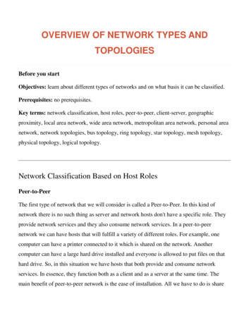
GNS3: adding new deviceDrag and drop new device from Devices Toolbar“ to workplace pane“””Network topology & GNS3 LAB
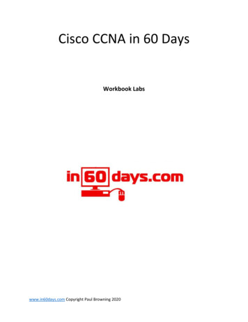
Configure deviceHardware setup (number and type of interfaces, etc. . . ). Includeswitching card (NM-16ESW) in each of your routers.Network topology & GNS3 LAB
Configure deviceHardware setup (number and type of interfaces, etc. . . ). Includeswitching card (NM-16ESW) in each of your routers.Network topology & GNS3 LAB
Run and configure/setup devicesNetwork topology & GNS3 LAB
Run and configure/setup devicesNetwork topology & GNS3 LAB
Run and configure/setup devicesNetwork topology & GNS3 LAB
Idle PCGNS3 emulator may consume up to 100 % of your CPU emulating routerprocessor. GNS 3 may find idle loops in emulated software and interruptemulation to let other processes on host computer run their part.Network topology & GNS3 LAB
Connecting devicesConnect devices by drawing connection between them – selectappropriate interfaces (if you plan to do switching labs, you have toconnect to switching interfaces (NM-16ESW))Network topology & GNS3 LAB
Campus topologyIIwhat is campus? Number of nearby buildings belonging to oneorganisation, usually connected by technology infrastructure.In computer network terms, campus usually connects:IIIclients – wired or wireless. These devices are not built to be highlyavailable, no need to connect them HA.servers – placed in the local datacenter are equiped with highavailability components (at least two power supplies, networkinterfaces, iLO, etc.)campus network topology should be designed highly-available (proneto failure of X components – X should be larger than 0 – dependingon ones needs) like servers. Network devices with multiple powersupplies connected to multiple power distribution sources, connectedto other network devices using multiple interfaces using separatedphysical path, etc. . . )Network topology & GNS3 LAB
Campus technology – hierarchical modelNetwork topology & GNS3 LAB
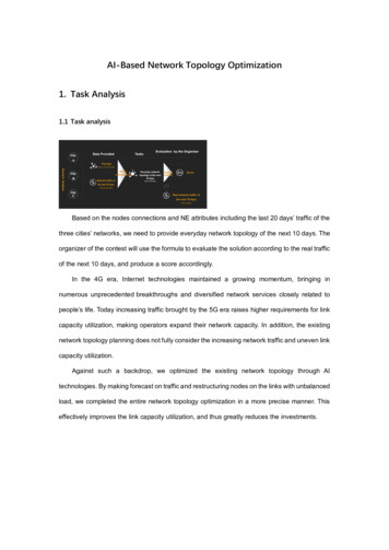
Campus technology – hierarchical modelI access layer – connects network enddevices to computer network (clientsand servers). Access layer switchesare placed on premises, where itmeets physical topology constraints(100m distance from clients Cat 5Ecables)Network topology & GNS3 LAB
Campus technology – hierarchical modelI distribution layer – aggregates linksfrom access layer switches andconnects them to core layer devicesI access layer – connects network enddevices to computer network (clientsand servers). Access layer switchesare placed on premises, where itmeets physical topology constraints(100m distance from clients Cat 5Ecables)Network topology & GNS3 LAB
Campus technology – hierarchical modelI core layer – backbone of campuscomputer network, usually located inthe centre of campus, minimisingneeds for fully meshed network.Provides connection to the outsideworld, advanced network services(dynamic routing, firewalls, loadbalancers, VRRP, HSRP, etc. . . )I distribution layer – aggregates linksfrom access layer switches andconnects them to core layer devicesI access layer – connects network enddevices to computer network (clientsand servers). Access layer switchesare placed on premises, where itmeets physical topology constraints(100m distance from clients Cat 5Ecables)Network topology & GNS3 LAB
Campus technology – hierarchical modelI core layer – backbone of campuscomputer network, usually located inthe centre of campus, minimisingneeds for fully meshed network.Provides connection to the outsideworld, advanced network services(dynamic routing, firewalls, loadbalancers, VRRP, HSRP, etc. . . )I distribution layer – aggregates linksfrom access layer switches andconnects them to core layer devicesI access layer – connects network enddevices to computer network (clientsand servers). Access layer switchesare placed on premises, where itmeets physical topology constraints(100m distance from clients Cat 5Ecables)Network topology & GNS3 LAB
L2 campus topologyCons:Ibroadcast and unknownunicast frames spread acrosswhole campusISTP creates tree topology,limiting use of additionalcommunication linesIrunning STP on big numberof switches may lead tonetwork problems(theoretically no, but. . . In”theory there is no differencebetween theory andpractice. In practice thereis.“)Pros:IIdoesn’t matter, where isend device located. It maybe part of every VLAN incampus.simplifies moving ofpersonel in campus. Noneed to change firewallrules, because IP addressmay stay the same.Network topology & GNS3 LAB
L3 campus topologyPros:IIIbroadcast and unknownunicast frames are limitedto smaller part of campus.L3 topology can use morebandwith/lines, becauseadvanced routing protocoldon’t create tree topologySTP creates smallertopologyCons:Itransfer od IP addressbetween buildings is limited(almost impossible)Ifrequent moving may leadto frequent changes offirewall rules (veryimpractical)Network topology & GNS3 LAB
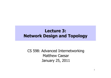
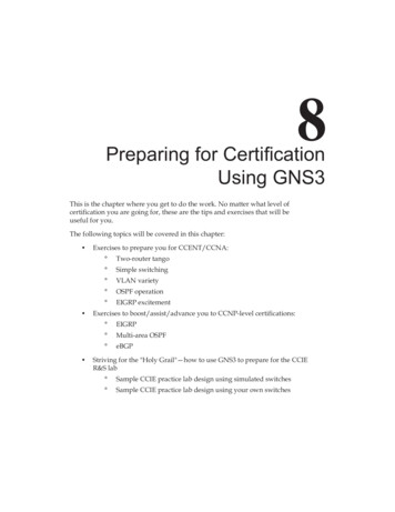
LAB 1: simple L2 topology1. make D1 root bridge inspanning tree topology2. make D2 secondary rootbridge in spanning treetopology (becomes rootbridge in case of D1 failure)3. ping from P1 to P24. find out path of PING andPING REPLY packetsHostP1P2IP192.168.1.11/24192.168.1.12/245. disconnect line L2 (shutdown line L2 on switch A1),observe how long does ittake to converge6. find out path of PING andPING REPLY packetsNetwork topology & GNS3 LAB
LAB 1: commands to useRouter enRouter#conf tRouter(config)#hostname D1D1(config)#spanning-tree vlan 1 root primary -- sets D1 switch as primary rootD1(config)#exitD1#show spanning-tree brief -- find out where root port isD1#show mac-address-table address PC Px MAC address D2(config)#spanning-tree vlan 1 root secondary -- sets D2 switch as secondary rootD2(config)#exitD2#show spanning-tree brief -- find out where root port isD2#show mac-address-table address PC Px MAC address A1(config)#interface FastEthernet 1/0A1(config-if)#shutdown -- disable ethernet port (causes STP recalculation)Network topology & GNS3 LAB
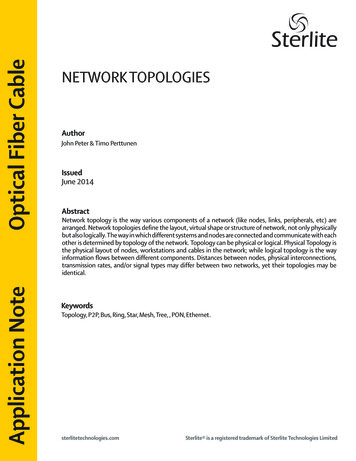
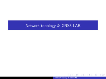
LAB 2: L3 topology & OSPFv2Topology: routed campus (routing between core and distribution layer,switching between distribution layer)Network topology & GNS3 LAB
LAB 2: descriptiondeviceA1, A2,A3, A4D1, D4D2, D3C1, C2P1P2P3P4descriptionaccess-switchprimary STP rootsecondary STP rootcore routersVLAN 10,192.168.10.10/24VLAN 20,192.168.20.20/24VLAN 30,192.168.30.30/24VLAN 40,192.168.40.40/24VLAN10 (HQ)20 (ENG)30 (PR)40 (HR)descriptionHSRP: D1 primary, D2 secondary,default GW: 192.168.10.1HSRP: D2 primary, D1 secondary,default GW: 192.168.20.1HSRP: D3 primary, D4 secondary,default GW: 192.168.30.1HSRP: D4 primary, D3 secondary,default GW: 192.168.40.1Network topology & GNS3 LAB
LAB 2: descriptionlineL1, L2, L3, L4,L5, L14, L15,L16, L17L6L7L8L9L10L11L12L13descriptionswitched, 802.1Q ted,routed,192.168.0.0/30, cost 50192.168.0.4/30, cost 1192.168.0.8/30, cost 10192.168.0.12/30, cost 50192.168.0.16/30, cost 1192.168.0.20/30, cost 1192.168.0.24/30, cost 20192.168.0.28/30, cost 1All links and IP networks are in OSPF area 0 (backbone), including allVLANs (advanced: VLANs as OSPF passive interfaces).Network topology & GNS3 LAB
LAB 2, task 1: topology and packet path1. run traceroute command between hosts P1 and P42. find out L3 path of packets between P1 and P43. find out L2 path of packets between P1 and P4Network topology & GNS3 LAB
LAB 2: commands to useD1#vlan databaseD1(vlan)#vlan 10 name HQD1(vlan)#vlan 20 name ENGD1(vlan)#applyD1(vlan)#exitcreate VLANsD1#conf tD1(config)#int Vlan 10configure VLAN interfaceD1(config-if)#ip address 192.168.10.2 255.255.255.0D1(config-if)#standby 10 ip 192.168.10.1default GW addressD1(config-if)#standby 10 priority 100HSRP priority, higher is betterD1(config-if)#no shutD1(config)#int FastEthernet 0/0D1(config-if)#ip address 192.168.0.5 255.255.255.252D1(config-if)#no shutD1(config-if)#ip ospf cost 50D1(config)#router ospf 1run OSPF processD1(config-router)#network 192.168.0.0 0.0.0.3 area 0 networks where OSPF runsD1(config-router)#network 192.168.0.4 0.0.0.3 area 0D1(config-router)#passive-interface Vlan10OSPF process doesn’t listen on this interfaceD1#show ip route Px IP address Network topology & GNS3 LAB
LAB 2, task 2: L3 convergence1. run ping command between hosts P1 and P4,2. disconnect line L7 and observe how many ping packets are lost.3. Connect line L7 and observe packet loss, if any.4. Try to minimize convergence time by lowering OSPF hello and deadtimers on interfaces (advanced: OSPF point-to-point link definitionon point to point links)5. Rerun this test again.Network topology & GNS3 LAB
ReferencesI GNS3, http://www.gns3.com/I Cisco validated design, Campus Zone design-zone-campus/index.htmlI Campus Network for High Availability Design Guide terprise/Campus/HA campus DG/hacampusdg.htmlI IP Routing: OSPF Configuration Guide, proute ospf/configuration/12-4/iro-12-4-book.htmlI Configuring HSRP, papp lNetwork topology & GNS3 LAB
spanning tree topology 2.make D2 secondary root bridge in spanning tree topology (becomes root bridge in case of D1 failure) 3. ping from P1 to P2 4. nd out path of PING and PING REPLY packets 5.disconnect line L2 (shut down line L2 on switch A1), observe how long does it take to converge 6. nd out path of PING and PING REPLY packets Network .