Transcription
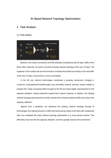
AI-Based Network Topology Optimization1. Task Analysis1.1 Task analysisBased on the nodes connections and NE attributes including the last 20 days’ traffic of thethree cities’ networks, we need to provide everyday network topology of the next 10 days. Theorganizer of the contest will use the formula to evaluate the solution according to the real trafficof the next 10 days, and produce a score accordingly.In the 4G era, Internet technologies maintained a growing momentum, bringing innumerous unprecedented breakthroughs and diversified network services closely related topeople’s life. Today increasing traffic brought by the 5G era raises higher requirements for linkcapacity utilization, making operators expand their network capacity. In addition, the existingnetwork topology planning does not fully consider the increasing network traffic and uneven linkcapacity utilization.Against such a backdrop, we optimized the existing network topology through AItechnologies. By making forecast on traffic and restructuring nodes on the links with unbalancedload, we completed the entire network topology optimization in a more precise manner. Thiseffectively improves the link capacity utilization, and thus greatly reduces the investments.
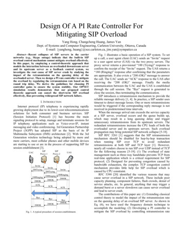
2. Network Topology Define:Based on the network topology and network attribute table provided, we found that 81.9% ofnetwork topology links of the cities A, B, and C failed to achieve load balancing.In our topology, ‘there are three types of nodes and links respectively’, namely, nodes G,H, J, and main ‘links, sublinks, hanging links.Main link: End nodes: node G or H Intermediate nodes: node H or J A-value of any intermediate node: the sameSublink: End nodes: both A-value of any node J: that of either end nodeon a main linkHanging link: End nodes: only one end node on a main link or a sublink A-value : that of the connected nodeConditions for edge adding: The distance between two nodes Number of nodes per link 30 Start and taild (d 500 m)nodes of any main link should be G or H
3. Our solution3.1 SolutionOur solution consists of two parts. The first part is traffic forecast. In this part, we built anLSTM neural model with TensorFlow.1)Data processing:Set the value of missing traffic to 0 and Sort out traffic by networkelement2)Training for traffic forecast: Use the TensorFlow to build an LSTM neural model. Inputdata to the model for training, and achieve the traffic of the next 10 days.3)Data post-processing: Sort out the forecast traffic of the next 10 days by dayThe second part is topology optimization. We used NetworkX and the DFS algorithm, andoptimized the network topology through a brand-new method.1)Network building: Use NetworkX to build network topology and set up the neighbor nodelibrary.2)Topology recovery:Use the “DFS algorithm” to search for main links, sort out crossconnected links, find out sublinks and hanging links via the Node-Removing Method, andbuild a link set.3)Topology recovery: Handle links with heavy and low loads via link combination and partiallink optimization4)Iteration for optimum topology: Implement successive iteration for 24 hours and selectthe optimum topology from the total 25 topology.5)Topology restructuring: Topology restructuring is proposed to optimize the links withheavy or low loads for a long period of time. The newly added edges are included in thesource topology of the next iteration.
4. Highlights3.1 Highlights (1): Enhanced LSTM Traffic Forecast Model for Traffic ChangeWe first built an LSTM neural network model with TensorFlow. Then we input 480 samples ofper-NE traffic of the last 20 days into the model to check whether our forecast is correct. Amongall these samples, 75% were used for training, and the other 25% were used for testing.To achieve the most accurate result, we finally set the most suitable parameters throughevaluating the RMSE of traffic and average time consumed, and achieved the traffic per hour inthe next 10 days. With multiprocessing technologies, we multiplied the network efficiency.3.2 Highlights (2): Topology in Full Status and Topology in Optimized StatusSecond, to conveniently adjust node connections of the topology, we also defined neighbornodes, neighbor links, network topology in full status, and network topology in optimized status.For neighbor node, we believe that one node on specified links is adjacent not only to theappropriate nodes on the same links, but also to the nodes located within 500 meters. We alsoformulated a neighbor link table to gather all the links where neighbor nodes are located together.In our solution, topology in full status indicates all neighbor nodes are connected. Suchtopology includes both existing connections and all potential neighbor links. We can either
transform topology in full status to the one in optimized status by removing appropriate edges,or achieve a topology in full status by adding some edges to the related topology in optimizedstatus in accordance with the neighbor link table.3.3 Highlights (3): DFS Node Removing Method to Accelerate Topology RecoveryThird, to make original network connections satisfy the requirements of desired networktopology, we took the lead in using the DFS algorithm and “Node-Removing Method” togetherto accelerate topology recovery."Node-Removing Method”:We then searched for sublinks and hanging links of each main link through our unique"Node-Removing Method”. Edges unhooked from the link when we remove two nodes fromone main link are identified as sublinks and hanging links of this main link.1) Select one main link and remove it2) Execute connected components method to identify all connected subgraphs.3) Review all these subgraphs, and identify the main link for those removed sublinks andhanging links. .4) Continue to remove other main links.3.4 Highlights (4):Topology Optimization from Multiple PerspectivesFourth, we further optimized the recovered network topology by adjusting the links withunbalanced loads through three different ways, including link combination , partial link
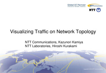
optimization, optimization by node transfer。1)link combination: We combined a link with unbalanced utilization with an appropriate linkby adding or removing related edges.2)partial link optimization: We transferred a sublink or hanging link with unbalancedutilization to an appropriate neighbor link.3)optimization by node transfer: We transferred nodes on links with heavy loads to other linksto balance link utilization in a precise manner.3.5 Highlights (5): Successive Iteration for Optimum TopologyThis flow chart describes how we optimize the link load status and keep pursuing optimumtopology through successive iteration.We optimized the current network topology with the forecast link utilization per hour,achieving the source topology for the iteration carried out in the next hour. After running suchsuccessive iteration for 24 times, we selected the best network topology of the day from the total25 topology. In the next day, this selected topology will be taken as the source topology and putinto another round of iteration.3.6 Highlights (6): Topology RestructuringAfter completing the required task, we also made in-depth study on the optimization ofnetwork topology, which is topology restructuring. Specifically speaking,
1)We first find out links with problems, namely the links with low or heavy loads for a longperiod of time.2)Second, we split the link with heavy loads into two links by connecting it with the nodes ona neighbor main link (including node G, H and J), and start the iteration of the new topologywith edges added in the previous step to improve the utilization of all links.3.7 Highlights (7): A Complete Network Topology Analysis and Optimization SystemLast but not the least, we set up a complete network topology analysis and optimizationsystem.We got the forecast network traffic through the enhanced LSTM model and recovered thebasic network topology via the “Node-Removing Method” and the DFS algorithm.Via edge adding, we extended the length of the main link and achieved an optimizedtopology.We applied the forecast network traffic to the optimized topology, made analysis based onthe link relations as shown by the neighbor link table, and optimize link capacity utilization in threedifferent ways.Through topology restructuring, we enhanced the entire network efficiency.
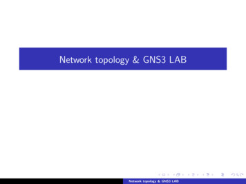
4.Effect4.1 Effect of the Model (1)With our solution, the proportion of the links with balanced load increased from 18.1%(based on the original topology give in the task) to 35.5%, witnessing an increase of 86%. Withoutstanding performance in both the preliminary contest and the finals, we ranked first amongall players in China.After the contest, we made further research on network restructuring, enabling the theproportion of the links with balanced load increased from 18.1% to 48.7%, with an increase of169%.Here we can see the proportion of links with balanced loads in different stages of networktopology optimization.1)This shows the proportion of such links in the original network topology before we startedthe optimization.2)The proportion increased to 35.5% after our basic network topology optimization throughthe aforementioned three methods.3)After restructuring the links within 500 meters, we increased the proportion to 43%.4)The result indicates that the links with balanced loads increased to 48.7%.
SummaryThrough selecting the most appropriate parameters, we controlled the error ratio of trafficforecast with the LSTM model within 3%.With the distributed and multi-process technologies, we increased the traffic forecastefficiency by 20 times.By introducing neighbor nodes, neighbor links, and other unique methods, we reduced theaverage time for topology optimization by 80%.Through the link optimization and topology restructuring, we increased the proportion ofthe links with balanced load by 169%.With outstanding performance, we ranked No.1 in both preliminary contest and the finalsin China.
2. Network Topology Define: Based on the network topology and network attribute table provided, we found that 81.9% of network topology links of the cities A, B, and C failed to achieve load balancing. In our topology, 'there are three types of nodes and links respectively', namely, nodes G, H, J, and main 'links, sublinks, hanging links.