Transcription
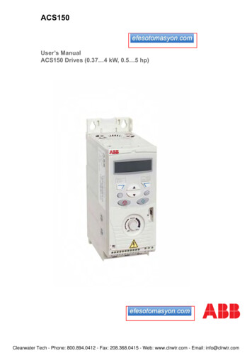
ACS150User’s ManualACS150 Drives (0.37 4 kW, 0.5 5 hp)Clearwater Tech - Phone: 800.894.0412 - Fax: 208.368.0415 - Web: www.clrwtr.com - Email: info@clrwtr.com
2ACS150 Drive manualsOPTION MANUALS (delivered with optional equipment andavailable in Internet)MUL1-R1 Installation instructions for ACS150 and ACS3503AFE68642868 (EN)MFDT-01 FlashDrop User's Manual3AFE68591074 (EN)MAINTENANCE MANUALS (available in Internet)Guide for Capacitor Reforming in ACS50, ACS55, ACS150,ACS350, ACS550 and ACH5503AFE68735190 (English)Clearwater Tech - Phone: 800.894.0412 - Fax: 208.368.0415 - Web: www.clrwtr.com - Email: info@clrwtr.com
ACS150 Drives0.37 4 kW0.5 5 hpUser’s Manual3AFE68576032 Rev BENEFFECTIVE: 12.9.2007 2007 ABB Oy. All Rights Reserved.Clearwater Tech - Phone: 800.894.0412 - Fax: 208.368.0415 - Web: www.clrwtr.com - Email: info@clrwtr.com
5SafetyWhat this chapter containsThe chapter contains the safety instructions which you must follow when installing,operating and servicing the drive. If ignored, physical injury or death may follow, ordamage may occur to the drive, motor or driven equipment. Read the safetyinstructions before you work on the drive.Use of warning symbolsThere are two types of safety warnings throughout this manual:Danger; electricity warns of high voltage which can cause physicalinjury and/or damage to the equipment.General danger warns about conditions, other than those caused byelectricity, which can result in physical injury and/or damage to theequipment.Installation and maintenance workThese warnings are intended for all who work on the drive, motor cable or motor.WARNING! Ignoring the following instructions can cause physical injury or death, ordamage to the equipment.Only qualified electricians are allowed to install and maintain the drive! Never work on the drive, motor cable or motor when input power is applied. Afterdisconnecting the input power, always wait for 5 minutes to let the intermediatecircuit capacitors discharge before you start working on the drive, motor or motorcable.Always ensure by measuring with a multimeter (impedance at least 1 Mohm) that:1. There is no voltage between the drive input phases U1, V1 and W1 and theground.2. There is no voltage between terminals BRK and BRK- and the ground. Do not work on the control cables when power is applied to the drive or to theexternal control circuits. Externally supplied control circuits may carry dangerousvoltage even when the input power of the drive is switched off. Do not make any insulation or voltage withstand tests on the drive.Note: Even when the motor is stopped, dangerous voltage is present at the powercircuit terminals U1, V1, W1 and U2, V2, W2 and BRK and BRK-.SafetyClearwater Tech - Phone: 800.894.0412 - Fax: 208.368.0415 - Web: www.clrwtr.com - Email: info@clrwtr.com
6WARNING! Ignoring the following instructions can cause physical injury or death, ordamage to the equipment. The drive is not field repairable. Never attempt to repair a malfunctioning drive;contact your local ABB representative or Authorized Service Center forreplacement. Make sure that dust from drilling does not enter the drive during the installation.Electrically conductive dust inside the drive may cause damage or lead tomalfunction. Ensure sufficient cooling.Operation and start-upThese warnings are intended for all who plan the operation, start up or operate thedrive.WARNING! Ignoring the following instructions can cause physical injury or death, ordamage to the equipment. Before adjusting the drive and putting it into service, make sure that the motorand all driven equipment are suitable for operation throughout the speed rangeprovided by the drive. The drive can be adjusted to operate the motor at speedsabove and below the speed provided by connecting the motor directly to thepower line. Do not activate automatic fault reset functions if dangerous situations can occur.When activated, these functions will reset the drive and resume operation after afault. Do not control the motor with an AC contactor or disconnecting device(disconnecting means); use instead the control panel start and stop keysandor external commands (I/O). The maximum allowed number of chargingcycles of the DC capacitors (i.e. power-ups by applying power) is two per minuteand the maximum total number of chargings is 15 000.Note: If an external source for start command is selected and it is ON, the drive will startimmediately after an input voltage break or fault reset unless the drive isconfigured for 3-wire (a pulse) start/stop. When the control location is not set to local (LOC not shown in the display), thestop key on the control panel will not stop the drive. To stop the drive using thecontrol panel, press the LOC/REM key LOC.REM and then the stop keySafetyClearwater Tech - Phone: 800.894.0412 - Fax: 208.368.0415 - Web: www.clrwtr.com - Email: info@clrwtr.com
7Table of contentsACS150 Drive manuals . . . . . . . . . . . . . . . . . . . . . . . . . . . . . . . . . . . . . . . . . . . . . . . . . . . . . . . . . . . 2SafetyWhat this chapter contains . . . . . . . . . . . . . . . . . . . . . . . . . . . . . . . . . . . . . . . . . . . . . . . . . . . . . . . .Use of warning symbols . . . . . . . . . . . . . . . . . . . . . . . . . . . . . . . . . . . . . . . . . . . . . . . . . . . . . . . . . .Installation and maintenance work . . . . . . . . . . . . . . . . . . . . . . . . . . . . . . . . . . . . . . . . . . . . . . . . . .Operation and start-up . . . . . . . . . . . . . . . . . . . . . . . . . . . . . . . . . . . . . . . . . . . . . . . . . . . . . . . . . . .5556Table of contentsAbout the manualWhat this chapter contains . . . . . . . . . . . . . . . . . . . . . . . . . . . . . . . . . . . . . . . . . . . . . . . . . . . . . . .Compatibility . . . . . . . . . . . . . . . . . . . . . . . . . . . . . . . . . . . . . . . . . . . . . . . . . . . . . . . . . . . . . . . . . .Intended audience . . . . . . . . . . . . . . . . . . . . . . . . . . . . . . . . . . . . . . . . . . . . . . . . . . . . . . . . . . . . . .Categorization according to the frame size . . . . . . . . . . . . . . . . . . . . . . . . . . . . . . . . . . . . . . . . . . .Product and service inquiries . . . . . . . . . . . . . . . . . . . . . . . . . . . . . . . . . . . . . . . . . . . . . . . . . . . . .Product training . . . . . . . . . . . . . . . . . . . . . . . . . . . . . . . . . . . . . . . . . . . . . . . . . . . . . . . . . . . . . . . .Providing feedback on ABB Drives manuals . . . . . . . . . . . . . . . . . . . . . . . . . . . . . . . . . . . . . . . . . .Installation and commissioning flowchart . . . . . . . . . . . . . . . . . . . . . . . . . . . . . . . . . . . . . . . . . . . .1313131313131314Hardware descriptionWhat this chapter contains . . . . . . . . . . . . . . . . . . . . . . . . . . . . . . . . . . . . . . . . . . . . . . . . . . . . . . .Overview . . . . . . . . . . . . . . . . . . . . . . . . . . . . . . . . . . . . . . . . . . . . . . . . . . . . . . . . . . . . . . . . . . . . .Overview: Connections and switch . . . . . . . . . . . . . . . . . . . . . . . . . . . . . . . . . . . . . . . . . . . . . . . . .Type code . . . . . . . . . . . . . . . . . . . . . . . . . . . . . . . . . . . . . . . . . . . . . . . . . . . . . . . . . . . . . . . . . . . .15151617Mechanical installationWhat this chapter contains . . . . . . . . . . . . . . . . . . . . . . . . . . . . . . . . . . . . . . . . . . . . . . . . . . . . . . .Unpacking the drive . . . . . . . . . . . . . . . . . . . . . . . . . . . . . . . . . . . . . . . . . . . . . . . . . . . . . . . . . . . . .Delivery check . . . . . . . . . . . . . . . . . . . . . . . . . . . . . . . . . . . . . . . . . . . . . . . . . . . . . . . . . . . . . .Before installation . . . . . . . . . . . . . . . . . . . . . . . . . . . . . . . . . . . . . . . . . . . . . . . . . . . . . . . . . . . . . .Requirements for the installation site . . . . . . . . . . . . . . . . . . . . . . . . . . . . . . . . . . . . . . . . . . . . .Wall . . . . . . . . . . . . . . . . . . . . . . . . . . . . . . . . . . . . . . . . . . . . . . . . . . . . . . . . . . . . . . . . . . . .Floor . . . . . . . . . . . . . . . . . . . . . . . . . . . . . . . . . . . . . . . . . . . . . . . . . . . . . . . . . . . . . . . . . . . .Free space around the drive . . . . . . . . . . . . . . . . . . . . . . . . . . . . . . . . . . . . . . . . . . . . . . . . .Mounting the drive . . . . . . . . . . . . . . . . . . . . . . . . . . . . . . . . . . . . . . . . . . . . . . . . . . . . . . . . . . . . . .Mount the drive . . . . . . . . . . . . . . . . . . . . . . . . . . . . . . . . . . . . . . . . . . . . . . . . . . . . . . . . . . . . .With screws . . . . . . . . . . . . . . . . . . . . . . . . . . . . . . . . . . . . . . . . . . . . . . . . . . . . . . . . . . . . . .On DIN rail . . . . . . . . . . . . . . . . . . . . . . . . . . . . . . . . . . . . . . . . . . . . . . . . . . . . . . . . . . . . . . .Fasten clamping plates . . . . . . . . . . . . . . . . . . . . . . . . . . . . . . . . . . . . . . . . . . . . . . . . . . . . . . . .19192020202020212121212122Table of contentsClearwater Tech - Phone: 800.894.0412 - Fax: 208.368.0415 - Web: www.clrwtr.com - Email: info@clrwtr.com
8Planning electrical installationWhat this chapter contains . . . . . . . . . . . . . . . . . . . . . . . . . . . . . . . . . . . . . . . . . . . . . . . . . . . . . . .Motor selection . . . . . . . . . . . . . . . . . . . . . . . . . . . . . . . . . . . . . . . . . . . . . . . . . . . . . . . . . . . . . . . .AC power line connection . . . . . . . . . . . . . . . . . . . . . . . . . . . . . . . . . . . . . . . . . . . . . . . . . . . . . . . .Supply disconnecting device . . . . . . . . . . . . . . . . . . . . . . . . . . . . . . . . . . . . . . . . . . . . . . . . . . . . .Thermal overload and short-circuit protection . . . . . . . . . . . . . . . . . . . . . . . . . . . . . . . . . . . . . . . .Protection against short-circuit inside the drive or in the supply cable . . . . . . . . . . . . . . . . . . .Protection against short-circuit in the motor and motor cable . . . . . . . . . . . . . . . . . . . . . . . . . .Thermal overload protection of the motor . . . . . . . . . . . . . . . . . . . . . . . . . . . . . . . . . . . . . . . . .Selecting the power cables . . . . . . . . . . . . . . . . . . . . . . . . . . . . . . . . . . . . . . . . . . . . . . . . . . . . . .General rules . . . . . . . . . . . . . . . . . . . . . . . . . . . . . . . . . . . . . . . . . . . . . . . . . . . . . . . . . . . . . . .Alternative power cable types . . . . . . . . . . . . . . . . . . . . . . . . . . . . . . . . . . . . . . . . . . . . . . . . . .Motor cable shield . . . . . . . . . . . . . . . . . . . . . . . . . . . . . . . . . . . . . . . . . . . . . . . . . . . . . . . . . . .Additional US requirements . . . . . . . . . . . . . . . . . . . . . . . . . . . . . . . . . . . . . . . . . . . . . . . . . . . .Conduit . . . . . . . . . . . . . . . . . . . . . . . . . . . . . . . . . . . . . . . . . . . . . . . . . . . . . . . . . . . . . . . . .Armored cable / shielded power cable . . . . . . . . . . . . . . . . . . . . . . . . . . . . . . . . . . . . . . . . .Protecting the relay output contact and attenuating disturbances in case of inductive loads . . . .Residual current device (RCD) compatibility . . . . . . . . . . . . . . . . . . . . . . . . . . . . . . . . . . . . . . . . .Selecting the control cables . . . . . . . . . . . . . . . . . . . . . . . . . . . . . . . . . . . . . . . . . . . . . . . . . . . . . .Relay cable . . . . . . . . . . . . . . . . . . . . . . . . . . . . . . . . . . . . . . . . . . . . . . . . . . . . . . . . . . . . . . . .Routing the cables . . . . . . . . . . . . . . . . . . . . . . . . . . . . . . . . . . . . . . . . . . . . . . . . . . . . . . . . . . . . .Control cable ducts . . . . . . . . . . . . . . . . . . . . . . . . . . . . . . . . . . . . . . . . . . . . . . . . . . . . . . . . . cal installationWhat this chapter contains . . . . . . . . . . . . . . . . . . . . . . . . . . . . . . . . . . . . . . . . . . . . . . . . . . . . . . .Checking the insulation of the assembly . . . . . . . . . . . . . . . . . . . . . . . . . . . . . . . . . . . . . . . . . . . .Drive . . . . . . . . . . . . . . . . . . . . . . . . . . . . . . . . . . . . . . . . . . . . . . . . . . . . . . . . . . . . . . . . . . . . .Input cable . . . . . . . . . . . . . . . . . . . . . . . . . . . . . . . . . . . . . . . . . . . . . . . . . . . . . . . . . . . . . . . . .Motor and motor cable . . . . . . . . . . . . . . . . . . . . . . . . . . . . . . . . . . . . . . . . . . . . . . . . . . . . . . . .Connecting the power cables . . . . . . . . . . . . . . . . . . . . . . . . . . . . . . . . . . . . . . . . . . . . . . . . . . . . .Connection diagram . . . . . . . . . . . . . . . . . . . . . . . . . . . . . . . . . . . . . . . . . . . . . . . . . . . . . . . . . .Procedure . . . . . . . . . . . . . . . . . . . . . . . . . . . . . . . . . . . . . . . . . . . . . . . . . . . . . . . . . . . . . . . . .Connecting the control cables . . . . . . . . . . . . . . . . . . . . . . . . . . . . . . . . . . . . . . . . . . . . . . . . . . . .I/O terminals . . . . . . . . . . . . . . . . . . . . . . . . . . . . . . . . . . . . . . . . . . . . . . . . . . . . . . . . . . . . . . .Procedure . . . . . . . . . . . . . . . . . . . . . . . . . . . . . . . . . . . . . . . . . . . . . . . . . . . . . . . . . . . . . . . . .3131313131323233343435Installation checklistChecklist . . . . . . . . . . . . . . . . . . . . . . . . . . . . . . . . . . . . . . . . . . . . . . . . . . . . . . . . . . . . . . . . . . . . . 37Start-up and control with I/OWhat this chapter contains . . . . . . . . . . . . . . . . . . . . . . . . . . . . . . . . . . . . . . . . . . . . . . . . . . . . . . . 39How to start up th
User s Manual ACS150 Drives (0.37–4 kW, 0.5–5 hp) Clearwater Tech - Phone: 800.894.0412 - Fax: 208.368.0415 - Web: www.clrwtr.com - Email: info@clrwtr.com. 2 ACS150 Drive manuals OPTION MANUALS (delivered with optional equipment and available in Internet) MUL1-R1 Installation instructions for ACS150 and ACS350 3AFE68642868 (EN) MFDT-01 FlashDrop User’s Manual 3AFE68591074