Transcription
.cJ. . .FRill ENGINEERl'NG LABOR/HOP". · D2C'LEHIGH UNIVE:RS1HVETHLEHEMI. ENNSYLVANIA.'.STRUCTURAL ANALYSISOFI-IOT-METAL LADLESbyKNUD-ENDRE KNUDSENAn Abridgment of a DissertationPresented to the Graduate Facultyof Lehigh Universityin Candidacy for the Degree ofDoctor of Philosophy-'Reprinted fromIRON AND STEEL ENGINEERVol. XXVINo. XIIDecember, 19-49
STRUCTURAL ANALYSISOFJ-IOT-METAL LADLESbyKNUD-ENDRE KNUDSENAn Abridgment of a DissertationPresented to the Graduate Facultyof Lehigh University.in Candidacy for the Degree ofDoctor of PhilosophyReprinted fromIRON AND STEEL ENGINEERVol. XXVINo. XIIDecember, 1949
STRESSES IN BOT METAL. LADLESBy K. E. KNUDSEN, WM. M. MUNSE and B. G. JOHNSTONFritz Engineering laboratorylehigh UniversityBethlehem, Pa.REPRINTED FROM IRON AND STEEL ENGINEER, DECEMBER, 1949
STRESSES IN BOT METAL LADLESBy K. E. KNUDSEN, WM. H. MUNSE and B. G. JOHNSTON,Fritz Engineering LaboratoryLehigh UniversityBethlehem, Pa. . . .this report describes the results of aresearch investigation sponsored andfinanced by the Association of Iron andSteel Engineers for the steel industry . THE designation "Hot-Metal Ladle," when us d inthis report, will mean a vessel, lined with refractorymaterial, used for conveying molten metal.During the extensive growth of the steel industrythere has been a consistent trend to increase thecapacity of hot-metal ladles. Larger furnaces and thcconvenience of pouring the whole furnace charge intoone ladle have combined to make this increase necessary. At the same time the allowable load on existingladle cranes and supporting structures is limited, thereby rendering any decrease in ladle dead weight directlyapplicable to increased capacity for molten metal. Theintroduction of the welded type ladle in 1932 openednew possibilities for decrease in dead weight (2). * Ovalshaped welded ladles came into use as an expedient toincrease capacity without interference with heightclearances and hook distances originally determinedfor the round riveted ladles.Thus, larger ladles are being built, new shapesintroduced, and the ratio of dead weight to ladlecapacity is forced down. This continual developmentgives significance to the application of more rationaland accurate stress analysis procedures in order tomaintain the required safety and dependability of hotmetal ladles. Little design information is available inthe technical literature. The design procedures used bythe different ladle manufacturers apparently have givencompletely satisfactory ladles. However, these procedures are in general based on assumptions which havenot necessarily been verified by tests.A program of experimental and theoretical stressanalyses of hot-metal ladles was therefore adopted bythe Association of Iron and Steel Engineers as a partof the Standardization Committee's postwar program.Fritz Engineering Laboratory of Lehigh Universityundertook the task of investigating the structuralbehavior of such ladles, initial work starting on June 15,Presented before AISE Annual Convention, Cleveland, Ohio, September 28, 1948Reprinted fromIRON AND STEEL ENGINEER, DECEMBER, 19491946. The general program was determined at a committee meeting in August 1946. It was decided to test3 models based on prototypes of 1.5Q-ton net capacity.Both riveted and welded construction was considered,and a model of an oval ladle was included. 'Additionalvariables were: number and size of stiffener rings, sizeof trunnions, angle of tilt, amount of load, and distancebetween the points of support on the trunnion pins.The important problems involving stresses due totemperature differentials caused by the molten metalare not considered in this investigation.A progress report -was presented before the annualconvention of the AISE in Pittsburgh, September 1947.The tests were completed in December 1947, and theexperimental program, procedures and results are described in detail in a separate test report (1). Thepresent report will therefore cover the conclusions only,illustrated by typical experimental data.The interest and advice given by Mr. IngvaldMadsen, Research Engineer of AISE; Mr: F. E. Kling,chairman of the ladle design committee, together withother members of the committee, were essential factorsin the planning and execution of the program. Thevaluable help of Mr. Paul Kaar, engineer of tests; andMr. Kenneth Harpel, foreman, is acknowledged, together with the valuable help of the many studentassistants in working up the strain gage data and preparing test result curves.LADLE MODELSThe ladle types chosen for this investigation representthree general types in use in the mills. They also reflectdifferent developments in ladle design. Ladle "A" is around riveted ladle, Ladle "B" is an oval welded ladle,and Ladle "C" is a round welded type with a dishedbottom. All three specimens are 1/5 scale models of Numb.r. refer to bibriography at end of report.3
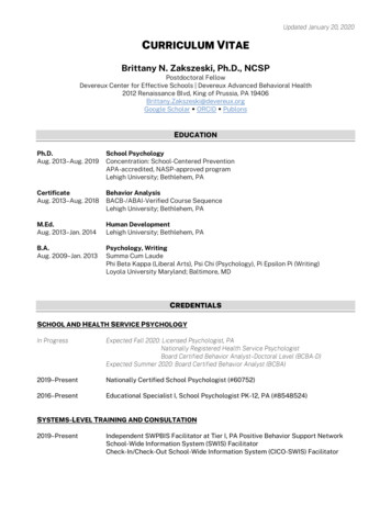
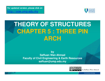
TABLE IACTUAL LADLE DIMENSIONSLadle shellSizeintonsLadleshapeLadle topdiameter, .ft-in.Type ofconstructionLadle bottom- - - - - - - - - - - " - - - - - - - - - Method DateLadleheight,ft-in.Type oftrunnionsThickShape ness, Brick,in.in.Thickness, Brick,in.in.Sideslopeofpourofdesign- - - - - - - - - - - - - - - - - - - - - - - - - - - - - - - - - - - - - - - - - - - - - - - - - - - - - - - - - pticalRoundRound. .-Weld.2-3315-26-78-11%8-4319-6U10-39-0 x 10-10%9-7Ys x ll-llYs11-311-9%9-1031 x 12-711-6 x 13-612-711-4 x 12-611-7U x'13-23111-5% x"14-5%10-10 x shFlatFlatDishDishDishFlatFlatDishFlatFlat.6Ys 8UYs 8-121% 71518U1% .16lU 819191% 7-9311% 8lU 1933191619431940193719291929194319421944from those of actual ladles approximately in the 5 to 1ratio, although material availability was to some extenta determining factor. The trunnion pins on all ladlesprototypes of 15Q.-ton net capacity. A survey of someactual ladle designs is given in Table I for reference.The dimensions and material thicknesses are reducedFigure 1 -%: 12%: 12%: 122*: 12%: 121: 12%: 12%: 12Ys: 121:121: 12Ys: 12Ys: 12Ys: 12H: 12Ys: 121: 12Ys: 12CastCastCastCastRivet.-Weld.CastCast10-1031 stCast13-2%13-6lCast12-131 JRivet.-Weld.12-1131 Welded12-11Welded5-46-78-98-610-810-0Ladle "A" is a one-fifth scale model of a lSD-ton riveted round ladle. L.'j'# / /It. I'j"x'\ ./;/- . --- e- - e-e-'- --: "'" \::.-\ J. .l. -. .- .1. -' -\\\ -f.-!-tr-- \I,.L 11/11)' "/1/\I· n w- "---- :::--- I. -.,,/'"-- -- - ·r ./0; rA. N1IiI/011,.,;;lt1/. nA/ x-f--. ··"f-"t4I "'L -- ·,.lfIhT. rJ JI,tT-c,. ri-. rlr.l-'Jl""* ",. - !-", . -j:-j.I"f- :----"l "Z'Pif'cJt &1-j . -----·"'---.-".,,s1,1I "",-.,-1 II"oI J o""M II ."( I,, loHId.';fo ilt3itle .1' ""'")/li"./c l ('o,,,,eel/.It4Reprinted fromIRON AND STEEL ENGINEER, DECEMBER, 1949
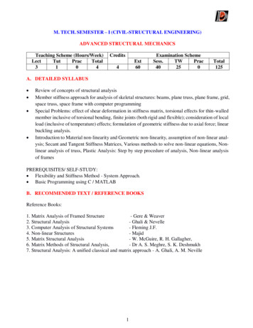
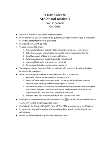
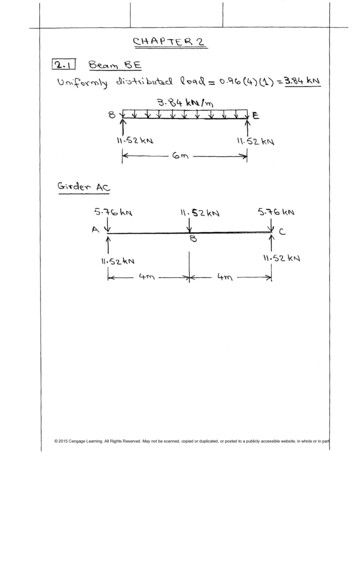
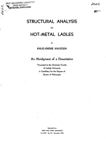
were made long enough to permit study of the effect ofhook spreading, as required by the test program.Some simplifications were made in the model design,as compared with actual ladles. The slag spout and 'thepouring device were eliminated. Special joints for facilitating the transport of the ladles were not considered.The additional trunnion pins sometimes used when theladle is placed in stands were disregarded. It is believedthat the elimination of the slag spout at the lip of theladle is the only significant deviation of those herementioned. The test results indicate that the effect ofthe lip ring on the structural b'ehavior of the ladle isgreater than emphasized in present design procedures., The serious discontinuity introduced in this ring by theslag spout seems therefore to deserve special consideration. Tests with such spouts added on the models wereproposed at one step in the development of the testprogram but were not adopted.Ladle "A" is shown in Figure 1. Attention is called tothe 1/16 in. additional plate on the bottom, similarplates on actual ladles being provided to protect againstheat radiation during the pouring operation. Ladle "A"was tested with two different size trunnion pairs, alsowith or without a stiffener band combined with thesmall pair of trunnions. Figure 2 gives details of ladle"B." The oval shape of the ladle is obtained by insertingFigure 2 -a straight middle section in the sides between thesemi-circular parts of the cross section. Ladle "B" hasa flat bottom with protection plate as in the case ofLadle "A." On Ladle "C," Figure 3, the bottom isdished and has no reinforcing plate. The stiffener ringsare of equal size and comparatively small due to theheavier middle section of the shell between the rings.The trunnions are built up of plates with no ribs of thetype used on Ladles "A" and "B," as may be seen fromFigures 4, 5, and 6.To conform with general practice in ladle manufacturing, the models were made of structural carbon steelconforming to ASTM Specification A-7 for heaviermaterial, and to ASTM Specification A 245-44T,Grade C, for the thin plates. The models were stressrelieved for one half hour at 1150 F after fabrication.Before testing, the ladles were lined with fireclay in away simulating the fire-brick lining used in actualladles. The thickness of the fireclay was %: in. on thesides and 1 in. on the bottom, slightly more on Ladle"A."TEST PROGRAM AND RESULTSIn the various tests, strains and deflections weremeasured at the points indicated in Figure 7 for LadleLadle "8" is a one-fifth scale model of a 150-ton welded oval ladle.ql----GEN[RAL NOTESLadle to be sIre" relieved byheating 10 uso-r, holdl"9 112hOUri and slowly COOIlft9. Alltrunnion Slru!s to b' 1/4e lhic:kas shown. Welds to be inaCCOrdance with the beslpractice and meeting AWS'londOI'd . All dilnel'l ions heldo. c;lose 01 possible. LI9ht' loge structural quollty flal hotrolled corbon 11 1 conforming10 ASTM speclfiC'Ofion A245 44TGRADE C to bt used for thinplot. Other· port, to me,.GRADE A 7 speclflcotlonl forstructural orod1116- bottom .Ilff lng plo', 10Mbolted 10 bottom of lodl, wltl.3/16" bolt 3/64"tdrlll t«,.1.boltom hoi Reprinted fromIRON AND STEEL ENGINEltR, DECEMBER, 19495
"A." The locatIOns tor the other ladles were similar.The strains were measured by means of bonded electricwire resistance gages, mounted on identical locationson the inside and outside ladle surfaces. The principalstresses and their directions, as well as the horizontaland vertical stress components, were computed fromthe measured strains. Horizontal deflections of the sidesand vertical deflections of the bottoms were measuredby means of mechanical deflection dials reading to1/1000 of one inch. Figure 8 gives an over-all picture ofthe test set-up.Actual ladles are loaded with molten metal weighingat an average 420 lb per cu ft. Due to obvious inconveniences in handling molten metal, mercury was usedas loading agent in the laboratory tests.A summary of the complete testing program is presented in Table II. The table lists the testing conditionsfor all tests on each ladle, and indicates the measurements taken in each case. The variables included inthe test program may be found from a study of Table II,and will be pointed out in connection with the discussionof their effect on the structural behavior of the ladles.The complete set of data is given in the unpublishedtest report, as previously mentioned. The AISE maybe consulted if some of this data should be desired.The general structural behavior of the ladle modelsFigure 3 -Ladlelie"deviates considerably from what is often assumed as abasis for design. A description of this behavior will begiven before the effect of the test variables is discussed.Figures 9 and 10 show representative deflectionresults. They were obtained for ladle "A" under conditions explained in the figures. Figure 9 shows thegeneral tendency of the horizontal cross section tobecome oval in shape due to the loading, the trunnionregions moving inward, and the regions between trunnions moving outward. Zero deflection is found approximately 45 degrees from the trunnion lines. The sidedeflections, as shown on vertical cross sections inFigure 10, are zero at the bottom and increase nearlylinearly to the maxilpum at the lip. Some irregularityis caused near the trunnion pin by the concentratedhook reaction, especially for the larger hook distance.The bottom deflection gives the picture of a partiallyrestrained circular plate under uniform load.The stresses in the stiffener rings are primarily bending stresses, hence these stresses should be proportionalto the change in curvature which may be visualized inFigure 9. This is confirmed by the stress measurements,as shown in Figures 11 and 12, for the outside and insideof the three stiffener rings on ladle "A." On each ring,the maximum stresses occur at the trunnion line andmidway between the trunnions. The ring stresses areis a one-fifth scale model of a 150-ton welded round ladle.AII,.".I " . o ".,l" . j'D-iI' 'iao,. "' .JfI.,.;. .N.106 "'FIlA #01' Sn . 1 . olB Jot.A 'w/HI/. . It ,.,.,."-"J.'" I""fl.fII/U. C;oeJ.s f"I ' . Rf,,! It""j. fIb. C' i"I'r".-.A. "" "H;" 01'-'.)0. All n h Jb be 4". r"lt""1 .1.".s.s «I."., .)' f'''V "".1110-'. W"':"9 YZ "1N'.s o .d JM"'7 .--1,,'9 / SS "hr l';' I .t"." JI . 1"/ It. '.".11 1,.1'0" s'.4/1do",vu''' J,. .""t .,,,,-11.1, , , n"",O ,.Iw,.r'.6 ,l"'ico.f, . ,,,,. .s J.,.1,,.,,/. 1tI,'d.l ,""Iw", #'C .-d. .,tM D., p,. I,,;. .,. . .1,."AWS.11".1'\0 Hg"",, 9---" ".,"".-.1,ci-t'::·J;;; / j· .l:9JI;;: "itJ ;:: '::'Z4' ''''6J,P Ic.l;c"I,,,,, A·HS-""r. t:i c.Reprinted fromIRON AND STEEL ENGINEER, DECEMBER, 1949
TABLE IISUMMARY OF THE TEST "Ladle"8"Ladle"e"LoadingagentTrunnion Mercury8 x8 8 x 87:4:16 x 87:4:16 x 87:4:16 x 87:4:16 x 8 16 x MercuryMercuryMercuryMercury1274 x lOY:;12 x lOY:;127:4: x lOY:;127:4: x lOY:;127:4: x lOY:;127:4: x lOY:;127:4: x lOY:;12 x lOY:;127:4: x lOY:;12 x lOY:;12 x curyMercuryMercuryWaterMercuryMercury10Ys x llY:;10Ys x 11Y:;l0Ys x llY:;10Ys x 11Y:;l0Ys x llY:;l0Ys x 11Y:;10YsxllY:;l0Ysx llY:;10Ys x 11Y:;l0Ys x llY:;10Ys x s(1 )Loadamount,per ;Y:;xxxxxxx.1007.210025507510075757591With both ringsWith both ringsWith both ringsWith both ringsWith both ringsWith both -ringsWith both ringsWith both ringsWith both 'ringsWith both ringsLess lower ringLess both ;7Y:;27'27Y:;2Y:;2Y:;2Y:;2Y:;2Y:;0000000 6 200'00Y:;Y:;Y:;With bandWithout bandWithout bandWithout bandWithout bandWithout bandWithout xxxxxxxxxxxxxxxxxx. xLoads given in volume per cent of load when liquid level is 3 in. from the lip.Hook distance is measured from the inside of the shell.Lining thicknesses given in comparison with unworn lining on actual ladles.In this test the ladle was supported in stands.largest on the lip ring and smallest on the lower stiffener,as are the deflections.The normal stresses in the side shell are considerablyless than the stiffener ring stresses, except near thejuncture with the bottom plate. The same is the casefor shear stresses in the side shell. Figure 13, giving. the distribution of vertical normal stresses on ladle "B,"clearly shows the high local stress peak near the bottom.These high stresses are similar to the discontinuity,stresses produced near the heads of pressure vessels.This stress problem has been' studied by the designdivision of the Pressure Vessel Research Committee ofthe Welding Research Council, 'and by several others.Although these stresses sometimes exceed the yieldpoint, experience from actual ladles seems to show thatthey do not endanger the safety of the ladle. The highdiscontinuity stresses also occur on the bottom-plateside of the juncture. Except in this narrow region, theflat bottoms sustain mainly a high and nearly uniformbending moment thrgughout, while in, the dished bottom smaller membrane stresses prevail.The general description of the structural behavior ofthe ladle models holds for all tests on all three models,and constitutes perhaps the most important result ofthis investigation. Actual ladles cover a large field ofReprinted fromIRON AND STEEL ENGINEER, DECEMBER, 1949types and variations in design. The tests made willtherefore not give the complete picture for any of them,but the general behavior as described is believed to becommon for all types. The experimental program did,however, consider some of the more important factorsin ladle design. The variables included may be dividedinto two groups, of which the first covers the variationin testing conditions, such as amount of load, distancebetween the hook supports, and angle of tilt. The othergroup includes structural variables; riveted versuswelded construction, round versus oval shape, flat ordished bottom, trunnion assembly size, and type andnumber of shell stiffener rings. The effect of thesevariables will be discussed in the order mentioned.The effect of amount of load on the deflections andstresses is partly demonstrated by Figures 9 to 15, andso is the effect of variation in the distance between thetwo supporting hooks. As a rule, stress and deflectiondata for the stiffener rings increase in almost linearproportion to both load and hook distance, as shownin Figures 16 and 17, respectively. Since the load distribution varies with amount of load, direct proportionality between load and stresses is not obvious. Table IIIshows the critical stresses in the rings for the smallestand the largest hook distance. A similar, but much less7
TABLE IIIEXPERIMENTAL STRESSES. PSI1I---2Locations0 : At trunnions90 : Betweentrunnionso : Outside surfacei: Inside surface----LipLadle "B"Ladle "A"8 x 8 in.8 x 8 in Trunnions 8 x 16 in.TrunnionsplusTrunnionsspacerband9I 10IFull load - 7.5 in. hook distance7I8Ladle "C"Ladle "A" Ladle "B" Ladle "C"With both Less lowerNostiffeners stiffeners stiffenersBothstiffeners8 x 16 in.Trunnions-10,800 28,400- 8,100 22,800- 6,900 23,400 9,200- 9,200 Yield-11,200 Yield-16,700 Yield-12,200 33,600 17,900-18,500 Yield90 0i 6,100-20,900 4,900-15,500 4,000-18,000 2,800- 6,300 3,500- 5,900 4,700- 7,700 10,100-17,200 7,700-23,800 5,700- 7,500 6,000- 9,5000 0i- 6,500 3,600- 5,400 1,200- 2,200 1,600-10,000 3,600- 3,100 3,700- 3,400 4,300- 3,200 4,100- 4,400 3,400-22,100 6,800- 6,700 7,30090 0i 4,400- 2,800 3,700- 1,800 3,500- 2,000 3,400 5,300- 3,400 6,700- 4,600 1,700- 2,700 5,600- 3,100 6,400- 4,200 9,300- 5,700- 2,500 2,000- 1,600 1,900- 1,000400 1,600100-0 0i0i 4,700- 2,300 4,600- 1,300 4,200- 1,900 4,300- 3,300 4,200- 2,300 2,000- 1,300 3,600- 2,700 7,600- 4,200 8,400- 7,000 4,400- er---- - - -- -----stiffener90 ----Ladle dead weight,without lining, IbFull Loadl evel-----L.JIIII2.5 or 7.5Hook Dis toneeconsistent variation is obtained for the side shell. Bottom stresses and deflections also increase with the load,but less rapidly than in the rings. This should beexpected, because membrane stresses prevail in thebottom when the deflections become larger than theplate thickness. Bottom stresses and deflections showvery little response to an increa e of the hook distance.One test was made with a ladle supported in stands,resting on the underside of the trunnion assemblies.This condition is essentially equivalent to a smallerhook distance, and the re ults fall in line with thosegiven above.Ladle "C" was tested in tilted positions up to 20degrees, with no increase of the stresses. At more than20 degrees, the stresses started to decrease due to outpour of the liquid load.Ladle model "A" is riveted, while the two othersrepresent welded construction. The three ladles differalso in other ways, and the test results are therefore notdirectly comparable. As an average, under equivalentconditions, the magnitude of the side deflections areabout thrce times as large for the riveted ladle as foreither of the two welded ones. This is at least partlyexplained by the fact that the average ratios of thebending stiffness of the stiffener rings above and below860i- - - ---Lower45IIIFull load - 2.5 in. hook distance30 ringTopI 400100100100 -------------- ---- ----- 1,300 3,100 200700 300300 -------100100the trunnions are one third as grcat in the riveted ladlea in either of the welded ladle. The experimentaltres es, essentials of which are given in Table III,show no consistent difference between riveted andwelded construction. The structural efficiency of theladles should be compared on a dead weight basis, sincemaximum live load within the ladle crane capacitylimit is of prime intere t. These weights are thereforegiven on the bottom of Table III.Ladle "B" is an oval ladle, while "A" and "C" havecircular cross sections. The deflections show the sametrend for all three ladles, and the stresses do not allowany conclusions as to preference. It is believed that themall degree of ellipticity commonly used has but aminor influence upon the structural behavior.Figure 4 -Repl'inted fromTrunnion assembly for ladle "A."IRON AND STEEL ENGINEER, DECEMBER,1949
rA study of the results from the tests of the flatbottoms on ladles "A" and "B" and the dished boLtomon ladle "C" allows definite conclusions in favor of thedished type. As mentioned earlier, the dished bottomplate carries the load mainly through membranestresses. The resulting deflection, Figure 15, is thereforeonly one sixth to one scventh of those dcvcloped in theflat bottoms, as shown in Figure 10. The figures alsoshow a different deflected shape for the dished bottom,which does not have the maximum deflection at thecenter point. The only re emblance between the twotypes is the in ensibility to variation in hook di tance.The flat bottom plate ustain high bending tre es,while the di hed hape show tensile stre e throughoutits thickne of about one fourth of the magnitude ofthe measured stresses on the flat bottom . The discontinuity stresses both in the side shell and in the bottomplate near the knuckle is even more reduced when usinga dished bottom.Ladle "A," the riveted model, wa te ted with twosizes of trunnion assemblies, 8 and 16 in. wide, covering34 and 68 degrees of the ladle circumference, respectively. The effect of the wider trunnions is to decreasethe ring stresses, as seen from columns 1 and 3 ofTable III. The reduction is largc t on the lip ring andFigure 5 - IrrIITrunnion assembly for ladle "B."on the top stiffener near the trunnion, and averages43 per cent. The side deflections with the wide trunnions are about 75 per cent of those obtained with thenarrow type. The bottom stresses and deflections staypractically unchanged.Columns 1 and fl in Table III give information on theeffect of the addition of a spacer band on ladle "A."This i X 8 i in. band, which is shown in Figure 1, isriveted to the sides of the trunnions, but not connectedwith the ladle hell. It is intended to carry most of thebending moment from trunnion to trunnion, thusrelieving the regular reinforcing rings. Tablc 1I I showsan avcrage reduction in ring stresses with 26 pel' centof those obtained without the spacer band. The additional weight of ladle steel material due to the band isfl5 per cent. Stresses in the side shell are also decreased,although not altogether consistently. The bottomstresses are not affected by the addition of the spacerband. A comparison of columns fl and 5 in Table IIIseems to indicatc that the same advantage may beReprinted fromIRON AND STEEL ENGINEER, DECEMBER, 1949Figure 6 -Trunnion assembly for ladle "C."obtained in a cheaper way by adding the equivalentsteel weight to the ladle shell thickness between the topand lower stiffeners. Higher lip ring stress is registeredin the latter case. Deflection tests show, on the otherhand, that the heavier shell more effectively resists thelocal bending effects caused by the moments introducedthrough the trunnions.Finally, the effect of removal of stiffener rings wasinvestigated on ladle "C." Some of the test stresses arerecorded in columns 5 to 7 in Table III. It shouldlberemembered in interpreting these results that ladle "c"has a heavy middle shell section and correspondinglywcak rings. Removal of the lower stiffener ring increa e the stresses on the top stiffener by 23 per centand the lip ring stress by 27 per cent on an average.With both the top and lower stiffeners removed, thelip ring tresses increase to an average of 143 per centabove those recorded with both stiffeners in place. Notest has been made with only the top stiffener removed,but the tests made indicate that the top stiffener iscomparatively more efficient than the lower stiffener.The deflection tests, Figure 15, also point to this conclusion, since the deformation at the top ring is considerably larger than at the other rings.DESIGN RECOMMENDATIONS AND STRESS ANALYSISThe conclusions which can be drawn from the testresults, as presented in the previous chapter, are incorporated in the design recommendations below, whichalso summarize recommendations made in variousarticles on ladle design. Statements which are referredto articles and not to parts of this investigation shouldbe regarded as the opinion of the author of the reference.M alerial - Ordinary low-carbon steel is recommended for hot-metal ladle construction. The temperatureeffect and high cost di courage the use of high-strengthalloy as a means of reducing the dead ,,,eight. For thetrunnion, a 3 per cent nickel, low carbon steel issometimes advised as being stronger and more resistantto pills of metal and slag (4). Reference 6 recommendsforged steel ASTM A-fl35 Class B for the trunnions.For trunnion pins and other parts for which reliabledesign methods allow the use of high stresses, the im-9
portance of a smooth finish of the entire surface isemphasized (3).Main ladle p1"oportions - The ladles are usuallyshaped like a frustum of a cone with a side slope, orincrease in radius, of one inch per 12 to 15 inches of theheight.The quasi-elliptical or oval cross section shape,introduced to increase the capacity under existing millconditions, is usually obtained by inserting a straightshell section at the trunnions. By making these middlesections slightly curved, lining conditions are improved(5). The ratio of minimum to maximum cross sectionwidth usually falls between 1 and %. On the oval ladlemodel this ratio is 0.82. No noticeable difference wasfound in structural behavior between the circular andthe oval ladle models. The round shape is preferredbecause of considerations of manufacturing cost andlining conditions.In Figure 18, the ladle height and diameter, oraverage diameter for oval shapes, is given as a functionof the carrying capacity for the ladles listed in Table I.A similar diagram for capacities up to 100 tons is givenin Reference (3). It is seen that the height is slightlylarger than the diameter up to approximately 12-footheight, or 125-ton capacity. Above that tonnage, theheight is smaller than the diameter. In Reference (4)it is advised that the diameter only should be increasedabove 125-ton capacity in order to keep down the headof metal during pouring.The location of the center of gravity of a fully loadedladle of 12-foot height should be about 15 inches belowthe trunnion pin center line, and correspondingly placedFigure 7 - The general location of the gages are shown inthis drawing for ladle "A." Similar locations wereused on the other ladles.Figure 8 - In this setup for the strain tests, the equipment for measuring the strains is seen in the foreground. The ladle is seen in the background in thevertical position. Tape seen on the ladle is used tokeep the leads from the electric strain gages in place.for othel' size ladles (4). A method for calculating thelocation of the center of gravity and the tipping momentis given in Reference (10). In Reference (6) it is recom0.00 Cmended that the center of gravity be d 6jnches below the trunnion center line, where C is theladle capacity in net tons. If this formula is used, lockbars to prevent tilting should not be required.Type of construction - The two commonly used typesof ladle construction, riveted and electric arc welded,were both represented in the experimental investigation.The riveted model underwent much larger deflectionsthan the welded ones under equivalent conditions, butthis was at least partly due to the lighter design of theriveted model. The experimental stresses showed noconsistent difference between the two types.The steel weight of the riveted ladle model was 280 Ibas compared to 250 and 340 Ib for the two welded models(Table III). In actual ladle design, the older rivetedtypes, without spouts, lining and stopper rings, weigh21 to 27 per cent of the rated capacity. The same percentage for similar welded typcs of more than 50-tonca
STRUCTURAL ANALYSIS OF I-IOT-METALLADLES by KNUD-ENDRE KNUDSEN An Abridgment of a Dissertation Presented to the Graduate Faculty of Lehigh University in Candidacy for the Degree of Doctor of Philosophy-' Reprinted from IRON AND STEEL ENGINEER Vol. XXVI No. XII December, 19-49 · D2C