Transcription
IQ plus 590-DC Digital Weight IndicatorVersion 1.0Installation Manual51778
ContentsAbout This Manual . 11.0Introduction. 11.11.21.31.42.0Operating Modes.Front Panel Keypad .Display Annunciators .Indicator Operations 444Toggle Gross/Net/Piece Count Mode.Toggle Units.Zero Scale.Acquire Tare (Pushbutton Tare) .Enter Tare (Keyed Tare).Remove Stored Tare Value.Print Ticket .Acquire Parts Sample.Installation . 52.1 Unpacking and Assembly . 52.2 Enclosure Disassembly . 52.3 Cable Connections . 52.3.1 Cable Grounding . 62.3.2 Load Cells . 62.3.3 Serial Communications. 62.42.52.62.72.83.0Enclosure Reassembly.Battery Installation .AC Adapter .Board Removal.Replacement Parts .77888Configuration. 113.1 Configuration Methods . 113.1.1 Revolution Scaleware Configuration . 113.1.2 EDP Command Configuration . 113.1.3 Front Panel Configuration . 123.2 Menu Structures and Parameter Descriptions. ion Menu.Format Menu.Calibration Menu .Serial Menu .Program Menu .Print Format Menu .Version Menu .14161819202222Calibration. 234.1 Front Panel Calibration. 234.2 EDP Command Calibration . 234.3 Revolution Scaleware Calibration . 24Technical training seminars are available through Rice Lake Weighing Systems.Course descriptions and dates can be viewed at www.rlws.com or obtained bycalling 715-234-9171 and asking for the training department. 2003 Rice Lake Weighing Systems. All rights reserved. Printed in the United States of America.Specifications subject to change without notice.Version 1.0, August 2003
5.0EDP Commands. 255.1 The EDP Command Set . 255.1.15.1.25.1.35.1.45.1.5Key Press Commands.Reporting Commands .The RESETCONFIGURATION Command.Parameter Setting Commands .Normal Mode Commands .25262626285.2 Saving and Transferring Data. 285.2.1 Saving Indicator Data to a Personal Computer . 285.2.2 Downloading Configuration Data from PC to Indicator. 286.07.0Counting Operations. 29Print Formatting . 317.1 Print Formatting Commands. 317.2 Customizing Print Formats. 317.2.1 Using the EDP Port . 327.2.2 Using the Front Panel . 327.2.3 Using Revolution Scaleware . 338.0Appendix . 348.18.28.38.48.58.6Error Messages .Continuous Output (Stream) Format .ASCII Character Chart .Front Panel Display Characters.Conversion Factors for Secondary Units .Digital Filtering .3434353738398.6.1 DIGFLx Parameters . 398.6.2 DFSENS and DFTHRH Parameters . 398.6.3 Setting the Digital Filter Parameters . 408.7 Test Mode . 408.8 Specifications . 42IQ plus 590-DC Limited Warranty. 43iiIQ plus 590-DC Installation Manual
About This ManualThis manual is intended for use by service techniciansresponsible for installing and servicing IQ plus 590-DC digital weight indicators.Configuration and calibration of the indicator can beaccomplished using the indicator front panel keys, theEDP command set, or Version 2.2 or later of theRevolution Scaleware configuration utility. SeeSection 3.1 on page 11 for information aboutconfiguration methods.1.0WarningSome procedures described in thismanual require work inside the indicatorenclosure. These procedures are to beperformedbyqualifiedservicepersonnel only.Authorized distributors and their employeescan view or download this manual from theRice Lake Weighing Systems distributorsite at www.rlws.com.The Operator Card included with this manualprovides basic operating instructions for users of theIQ plus 590-DC. Please leave the Operator Card withthe indicator when installation and configuration arecomplete.IntroductionThe IQ plus 590-DC is a single-channel digital weightindicator housed in a NEMA 4X/IP66-rated stainlesssteel enclosure. The indicator front panel consists of a1-inch (25 mm), six-digit, liquid crystal (LCD)display and 19-button keypad. Features include: Drives up to four 350Ω or eight 700Ω loadcells Supports 4- and 6-wire load cell connections Electronic data processing (EDP) port for fullduplex, RS-232 communications at up to19200 bps Powered by 6 C batteries for completeportability AC adapter for 115 or 230 VAC power Configurable standby mode limits indicatorpower consumption when scale is inactive Piece count mode for basic parts countingfunctions.The IQ plus 590-DC is NTEP-certified for Classes IIIand III L at 10,000 divisions. See Section 8.8 onpage 42 for detailed specifications.Piece count mode1.1Test modeOperating ModesThe IQ plus 590-DC has several modes of operation:Normal (weighing) modeNormal mode is the “production” mode of theindicator. The indicator displays gross or netweights as required, using the LCD annunciatorsdescribed in Section 1.3 on page 3 to indicatescale status and the type of weight valuedisplayed. Once configuration is complete and alegal seal is affixed to the back of the indicator,the IQ plus 590-DC can operate only in normalmode.In piece count mode, the indicator display showsthe number of parts on the scale rather than theweight of those parts. Piece count mode has twosubmodes: Count display mode displays the current partscount and allows ticket printing using theCFMT print format. Sample acquisition mode is used to calibratethe indicator for parts counting.Operator access to piece count mode is disabledwhen the indicator is shipped from the factory.See Section 6.0 on page 29 for detailedinformation about counting operations.Setup modeMost of the procedures described in this manualrequire the indicator to be in setup mode,including configuration and calibration.To enter setup mode, remove the large fillisterhead screw from the enclosure backplate. Insert ascrewdriver or a similar tool into the access holeand press the setup switch once. The indicatordisplay changes to show the word CONFIG.Test mode provides a number of diagnosticfunctions for the IQ plus 590-DC indicator. Likesetup mode, test mode is entered using the setupswitch. See Section 8.7 on page 40 for moreinformation about entering and using test mode.Standby modeStandby mode is a configurable low-power modeused to extend battery life when the indicator isinactive. In standby mode, the LCD display showsthe word STNDBY; press any key to exit standbymode. See Section 3.2.5 on page 20 forinformation about configuring standby mode.Introduction1
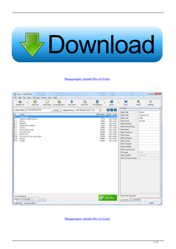
1.2Front Panel KeypadFigure 1-1 shows the IQ plus 590-DC front panel keys and the key functions assigned in normal mode.The symbols shown above the keys in Figure 1-1 (representing up, down, enter, left, right) describe the keyfunctions assigned in setup mode. In setup mode, the keys are used to navigate through menus, select digitswithin numeric values, and increment/decrement values. See Section 3.1.3 on page 12 for information aboutusing the front panel keys in setup mode.Labels under the keys in Figure 1-1 describe the key functions used in piece count mode. See Section 6.0 onpage 29 for more information about counting operations.NORMAL MODE KEY FUNCTIONSSet gross weightto zeroAcquire tareSwitch betweenprimary andsecondary unitsSwitch betweengross, net, andpiece count 23457890Send data toserial portPRINTPRINTCLEARDISPLAYTARE6POWERI/ODisplay currenttare weightPower on/offFigure 1-1. Front Panel Key Functions in Normal Mode2IQ plus 590-DC Installation Manual
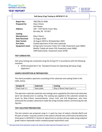
1.3Display AnnunciatorsThe IQ plus 590-DC display uses a set of LCDannunciators to provide additional information aboutthe value being displayed. Figure 1-2 on page 3 showsthese annunciators and their meanings.G The displayed weight is a gross weight.N The displayed weight is a net weight.Scale is at standstill or within the specified motionband. Some operations, including zero, tare, andprinting functions, can only be done when thestandstill symbol is shown.Center of zero. Gross weight is within 0.25graduations of zero. This annunciator lights when thescale is zeroed.Indicates that a tare has been entered. The tare valuecan be entered by pressing the TARE key on thekeypad or by sending the KTARE EDP command. SeeSection 5.0 on page 25 for information about the EDPcommand set.Indicates that the battery charge is low.lb, kg, PCThree arrow annunciators on the right side of the LCDdisplay indicate the units associated with thedisplayed value. The bottom arrow annunciator (PC)is lit when the indicator is in piece count mode. Thetop and middle arrows, labeled lb and kg, showprimary and secondary units, as described below: If the displayed weight is in pounds, the top arrow(lb) is lit; if kilograms, the middle arrow (kg) islit. If the primary unit of weight is pounds, the middle(kg) arrow is lit for secondary units—or, if theprimary unit is kilograms, the top (lb) arrow is litfor secondary units, unless the secondary unit ofweight is the same as the primary unit. If neither primary nor secondary units are poundsor kilograms, the top arrow is used as a primaryunits annunciator and the middle arrow is used asthe secondary units annunciator. A set ofreplacement overlay decals is included in the partskit for units other than pounds and kilograms.See Section 3.2.2 on page 16 for information aboutconfiguring primary and secondary display units.lbPrimaryDisplayed unitskgPCGross modeNet modeStandstillSecondaryPiece count modeTare in systemCenter of zeroLow batteryFigure 1-2. IQ plus 590-DC Display AnnunciatorsIntroduction3
1.4Indicator Operations1.4.6Remove Stored Tare ValueBasic IQ plus 590-DC operations are summarizedbelow:1. Remove all weight from the scale and wait forthe standstill annunciator ().1.4.1annunciator goes2. Press the TARE key. Theoff, indicating the tare value has beenremoved.Indicators with the REGULA parameter set toNONE or NTEP (see Section 3.2.5 on page 20)can clear a stored tare value using the followingprocedure:1. Press DISPLAY TARE to show the stored tarevalue.2. Press the CLEAR key twice to remove thestored tare.Toggle Gross/Net/Piece Count ModePress the GROSS/NET key to switch the display modebetween gross, net, and piece count modes. If a tarevalue has been entered or acquired, the net value is thegross weight minus the tare. If access to piece countmode is disabled, pressing the GROSS/NET keyswitches between gross and net modes only.Gross mode is shown by the G annunciator; net modeis shown by the N annunciator. Piece count mode isshown by the LCD annunciator adjacent to the PC atthe right edge of the display.1.4.2Toggle UnitsPress the UNITS key to switch between primary andsecondary units. The units annunciator arrow on theright side of the LCD display points to the unitsidentifier.1.4.3Zero Scale1. In gross mode, remove all weight from thescale and wait for the standstill annunciator().2. Press the ZERO key. The center of zero() annunciator lights to indicate thescale is zeroed.1.4.4Acquire Tare (Pushbutton Tare)1. Place container on scale and wait for thestandstill annunciator ().2. Press the TARE key to acquire the tare weightof the container.3. Net weight is displayed and theannunciator lit to show the tare value wasacquired.1.4.5Enter Tare (Keyed Tare)1. Use the numeric keypad to enter the tarevalue, then press the TARE key.2. Net weight is displayed and theannunciator lit to show the tare value wasentered.4IQ plus 590-DC Installation Manual1.4.7Print Ticket1. Wait for the standstill annunciator ().2. Press the PRINT key to send data to the serialport.1.4.8Acquire Parts Sample1. Place empty parts container on scale. Wait forthe standstill annunciator (), then pressTARE to acquire the tare weight of thecontainer.2. Press MODE to enter piece count mode.3. Press the SAMPLE (UNITS) key to entersample acquisition mode.4. The indicator display shows the messageAddnnn, where nnn is the sample quantity tobe placed on the scale. You can do one of thefollowing: Add the number of parts shown. Choose a different sample size. Press theS A M P L E key to scroll through theselectable sample quantities (5, 10, 20,50, 100) or use the numeric keypad tospecify a custom sample size. Specify a known piece weight. Press theS A M P L E key to scroll through theselectable sample quantities until the PCWGT prompt is shown. Use the numerickeypad to enter the piece weight.5. Once the sample quantity is on the scale,press ENTER to calibrate the indicator forcounting the new parts. If a sample size wasspecified, the indicator display shows themessage –CNT– as it acquires the sampleweight, then switches to count display modeand shows the part quantity. If a known pieceweight was specified, the display switches tocount display mode immediately.
2.0InstallationThis section describes procedures for connecting loadcell and serial communications cables to the IQ plus590-DC indicator. Instructions for battery and CPUboard replacement are included, along with assemblydrawings and parts lists for the service technician.Caution2.1 Use a wrist strap to ground yourself andprotect components from electrostaticdischarge (ESD) when working insidethe indicator enclosure. Unpacking and AssemblyImmediately after unpacking, visually inspect the IQplus 590-DC to ensure all components are includedand undamaged. The shipping carton should containthe indicator with attached tilt stand, this manual, anda parts kit. If any parts were damaged in shipment,notify Rice Lake Weighing Systems and the shipperimmediately.The parts kit contains the items listed below: Capacity, annunciator, and identificationlabels. The annunciator label (PN 53374)provides replacement overlay decals for thedisplayed units annunciators. 3-position (PN 15888) and 7-position (PN23165) pluggable terminal blocks for load celland serial communications connectors.2.3 2.2One 8-32NC x 7/16 fillister head screw (PN30623). This screw occupies the hole belowthe setup switch access screw on the indicatorbackplate (see Figure 2-4 on page 7).Two 8-32NC x 3/8 machine screws (PN14862) for the indicator backplate (see #10 inFigure 2-7 on page 10).Five neoprene washers (PN 45042) forbackplate screws included in the parts kit.Four rubber bumpers (“feet”) for the tilt stand,PN 42149.Two each of grounding clamps (PN 53075),external tooth lock washers (PN 15133), andke p n u t s ( P N 1 4 6 7 6 ) f o r c a b l e s h i e l dgrounding against the backplate.Enclosure DisassemblyThe indicator enclosure must be opened to connectload cell and communications cables.Power off the indicator and disconnect the AC adapter,if necessary. Place the indicator face-down on anantistatic work mat. Remove the screws that hold thebackplate to the enclosure body, then lift the backplateaway from the enclosure. Disconnect battery cable toconnector J3, then set the backplate assembly aside.Cable ConnectionsThe IQ plus 590-DC provides two cord grips for cabling into the indicator: one for the load cell cable, the otherfor serial communications.Serial communicationscable cord gripBattery coverLoad cell cablecord gripAC adapterport coverFigure 2-1. IQ plus 590-DC Backplate, Showing Key Component LocationsInstallation5
2.3.1Cable Grounding2.3.2Except for the power cord, all cables routed throughthe cord grips should be grounded against theindicator backplate. Do the following to groundshielded cables: Use the lockwashers, clamps, and kep nutsprovided in the parts kit to install groundingclamps on the backplate studs adjacent to cordgrips. Install grounding clamps only for cordgrips that will be used; do not tighten nuts. Route cables through cord grips and groundingclamps to determine cable lengths required toreach cable connectors. Mark cables to removeinsulation and shield as described below: For cables with foil shielding, strip insulationand foil from the cable half an inch (15 mm)past the grounding clamp (see Figure 2-2).Fold the foil shield back on the cable wherethe cable passes through the clamp. Ensuresilver (conductive) side of foil is turnedoutward for contact with the groundingclamp. For cables with braided shielding, strip cableinsulation and braided shield from a point justpast the grounding clamp. Strip another halfinch (15 mm) of insulation only to expose thebraid where the cable passes through theclamp (see Figure 2-2). For load cell cables, cut the shield wire just pastthe grounding clamp. Shield wire function isprovided by contact between the cable shieldand the grounding clamp. Route stripped cables through cord grips andclamps. Ensure shields contact groundingclamps as shown in Figure 2-2. Tightengrounding clamp nuts. Finish installation using cable mounts and ties tosecure cables inside of indicator enclosure.NOTE: Install lockwashersfirst, against backplate,under grounding clampCord gripCut insulation herefor braided cablesInsulated cableFoil (silver side out)Shield wire (cut)BraidGrounding clampCut insulation herefor foil-shielded cablesLength of foil before foldingback on cable insulationFigure 2-2. Grounding Clamp Attachment for Foil-Shieldedand Braided CablingNOTE: A grounding screw is provided on the indicatorbackplate for connecting a grouding wire (see Figure 2.4on page 7).6IQ plus 590-DC Installation ManualLoad CellsTo attach cable from a load cell or junction box,remove connector J1 from the board. The connectorplugs into a header on the board. Connect cable fromthe load cell or junction box through the load cellcable cord grip to connector J1 as shown in Table 2-1.If using 6-wire load cell cable (with sense wires),remove jumpers JP1 and JP2 before reinstallingconnector J1 (see Figure 2-3 on page 7). For 4-wireinstallation, leave jumpers JP1 and JP2 on.When connections are complete, reinstall connectorJ1 on the board.J1 PinFunction1 SIG2–SIG3 SENSE4–SENSE5SHIELD (see NOTE below)6 EXC7–EXCNOTES: SHIELD wire connection not used. Use groundingprocedure described in Section 2.3.1 on page 6. For 6-wire connections, remove jumpers JP1 and JP2.Table 2-1. J1 Pin Assignments2.3.3Serial CommunicationsTo attach serial communications cables, removeconnector J2 from the board (see Figure 2-3 on page7). Connect communications cable through cord gripto connector J2 as shown in Table 2-2.Once cables are attached, reconnect J2 to the headeron the board.The IQ plus 590-DC serial port supports full duplexRS-232 communications for connections to printers,PCs, and other attached devices. See Section 3.0 onpage 11 for general configuration information; seeSection 3.2.4 on page 19 for serial port configuration.J2 PinFunction1RS-232 TxD2RS-232 Ground3RS-232 RxDTable 2-2. J2 Pin Assignments
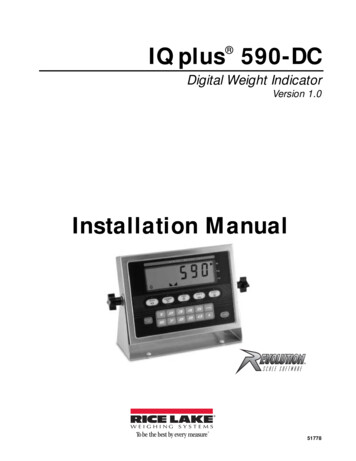
J2GNDC5C13C4C11U4R7R6C10C1U3U2C9C8Display DriversR8U7C287L1C31 2C41C74C87C88C89R35R36R42R48C94R41R47C77C7811J61To SetupSwitchR50J51ACBatteryInput 5J4R37J3R43R24R23 D4D5C76 J71C84F1D3C95C80C81R25C73C71C72A/D 6C34R29U15VR2C39C42C37RN1C35JP1 JP2C79EMI1R11R12C29R15R14U11Q1R26D2C331 SIGC25C22U10VR1 C302R13–SIGC20C21AGNDC123TxDU9XT1DGNDLOAD CELLCONNECTOR–EXC SENSEGND1R9D1J1C7RxD2C18 MicrocontrollerU1SERIAL PORT3U8C14R4C3C2R3R2R1FLASH RAMC23C19U5C6R5RESETGNDC17C24RICE LAKE WEIGHING SYSTEMSKeypad Connectors(J5 and J7)Figure 2-3. IQ plus 590-DC CPU Board2.4Enclosure ReassemblyOnce cabling is complete, position the backplate overthe enclosure, reconnect battery cable, and reinstallthe backplate screws. Use the torque pattern shown inFigure 2-4 to prevent distorting the backplate gasket.Torque screws to 15 in-lb (1.7 N-m).Torquepattern1742.5Battery InstallationTo install or replace batteries, do the following:1. Remove the four thumbscrews that hold thebattery cover to the enclosure backplate.2. Install six alkaline C-cell batteries as shownin Figure 2-5.3. Replace the battery cover and reinstallthumbscrews. Torque thumbscrews to 15 in-lb(1.7 N-m).6Torque backplate screwsto 15 in-lb (1.7 N-m)2GroundingScrew–3– – – – 8– 5Figure 2-4. IQ plus 590-DC Enclosure BackplateFigure 2-5. Battery InstallationInstallation7
2.6AC AdapterThe AC adapter can be used to provide power to theindicator if battery power is low and AC power isavailable. Use only the adapter supplied with theindicator.To use the AC adapter, do the following:1. Remove the top screw from the AC adapterport cover.2. Loosen the bottom screw, then rotate the portcover to expose the AC adapter port (seeFigure 2-6).3. Reinstall the top screw in the backplate.4. Plug AC adapter from power outlet to theindicator adapter port.Close the adapter port cover and reinstall screws asdescribed in Section 2.4 when not using the ACadapter.CautionThe IQ plus 590-DC enclosure cannotbe rated for NEMA 4X/IP66 applicationswith the AC adapter port cover open.Do not use the AC adapter in washdown environments.2.8Figure 2-6. AC Adapter Port Cover2.7Board RemovalIf you must remove the IQ plus 590-DC CPU board,use the following procedure:1. Disconnect power to the indicator. Loosencord grips and remove backplate as describedin Section 2.2 on page 5.Replacement PartsTable 2-3 lists replacement parts for the IQ plus 590-DC, including all parts referenced in the assembly drawing(see Figure 2-7 on page 10).RefNumberPN149520Battery cover thumb screws (4)—47939Battery cover - old style 4 x 4.5" dimension (1)271352Battery cover - new style 3 x 7" dimension (1)—49557
IQ plus 590-DC Installation Manual 1.4 Indicator Operations Basic IQ plus 590-DC operations are summarized below: 1.4.1 Toggle Gross/Net/Piece Count Mode Press the GROSS/NET key to switch the display mode between gross, net, and piece count modes. If a tare value has been entered or acquired, the net value is the gross weight minus the tare.