Transcription
OZYMANDIASThe Making of .High Performance Software Defined RadioOpen Source Hardware and Software ProjectProject Description: http://hpsdr.org/Hardware Project #3Oyzmanidas BoardPart #2The Making of OZYGraphics und LayoutProject CoordinatorBoard DesignHorst Gruchow, DL6KBFPhil Covington, N8VBPhil Covington, N8VB1Ver. 1.1; Okt. 28, 2008 DL6KBF
The Making of .OZYMANDIASChapter 1: Preliminaries1.1 Physical and mentalpreparationThe HPSDR High Performance SoftwareDefined Radio has become one of the mostattended HAM Radio projects worldwide.Since ATLAS, JANUS and OZYMANDIASboards are out supporting the FLEXRADIO SDR-1000 transceiver audio processing anoverwhelming amount of people have ordered the whole set of finished boards fortheir radio.Surprisingly enough also bare PCBs have beensold in quite good numbers. That's where thisdocumentation kicks in. People should not beleft alone with their boards even if they areexperienced builders. This whole project isvery complex also from the parts point ofview and requires exact preparation in orderto avoid mistakes. If you make only one it canbe kind of difficult to find it.But enough words, just let's have fun. That'swhat this is all about.73HorstDL6KBFBefore you start building anything pleasecheck yourself regarding your personalphysical and mental condition. You should askyourself if you are physically so well that youcould start such a project. If you arehyperactive or have problems with tremor inyour hands I would recommend that you findanother day to start or even stay away fromthis and buy a finished board.If you just had a fight with your wife or yourboss and you are still very angry or frustrated inside please don't start soldering. Youdefinitely will throw all the tiny parts on thefloor and can't find them anymore.How you should be:- in a good health condition- in a goooooood mood- calm and cool inside- have self-confidenceYou should be knowing what you aredoing!1.2 Workbench preparation1.2.1 TableThe work table should be totally cleaned upand emptied before starting any work on OZY.This makes it easier to find any part whichpossibly jumps off the tweezers.1.2.2 ESD (ElectroStatic Discharge)preventionSince most of the ICs on OZY are verysensitive to ESD it is recommended that youuse an ESD matt. This should be connected atleast to the solder station ESD connector.Before touching any IC you should place bothhands flat on the matt in order to dischargeyourself. Alternatively wear an ESD straparound your wrist which is connected either tothe matt or to the same potential as the matt.I use an ESD matt of about 60x50 cm² whichis fairly cheap (approx. 15 EUR). It is madefrom PVC which has the advantage of alsohaving an anti-slip surface. I am usuallyplacing the PCB directly on the matt withoutusing any vise. This makes the PCB handlingvery easy and convenient.You also should be familiar with thebasic SMT soldering techniques!2Ver. 1.1; Okt. 28, 2008 DL6KBF
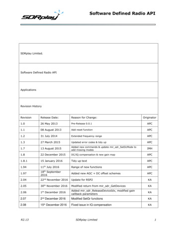
The Making of .OZYMANDIASChapter 1: Preliminaries1.3 Soldering toolsas small as possible. I am using a wirediameter of 0.5 mm. If you can get a smallerwire diameter this should be even better. InEurope the readily availabe minimumdiameter is 0.5 mm.For this type of project a good qualitysoldering tool is very essential. Preferably asoldering station with electronic temperaturecontrol and a wattage of around 50W to 80Wshould be used.- forget about cheap irons. They are too hot. forget about so-called SMD soldering needles. They usually have around 8 watts whichafter my experience is useless.Most important:Buy the finest solder tip for your iron whichyou can get. Mine has a tip diameter of 0.2mm (around .01 inch). This is suitable forsoldering even the fine pitch CPLD.Alternative methods include various kinds ofreflow or hot air soldering techniques. Youcan find many details about reflowing or hotair soldering on the internet in the variousmicrocontroller forums or on some HAMwebsites.But be warned:I tried to reflow OZY with my temperaturecontrolled pizza oven and I had a very badexperience with the board delaminatingdespite the correct temperature profile.That's what I am using1.3.1 Solder wireSolder containing leadWith solder wire you have the choice of usingwire containing lead or the new lead-free(RoHS compliant) solder wire. Leaded solderwire is still available and you do not need tochange your soldering habbits which you mostprobably have developed over the years.Lead-free solder wire has the disadvantage ofa higher melting temperature which you haveto get used to. So, if you decide to use leadfree solder wire please do some test solderingbefore getting on OZY.Very important:The diameter of the solder wire should beLead-free solder3Ver. 1.1; Okt. 28, 2008 DL6KBF
OZYMANDIASThe Making of .Chapter 1: Preliminaries1.3.2 Solder Flux1.4 Essential toolsActually my personal experience with solderflux is twofold:- it is a fantastic aid for soldering- depending on the kind of flux it bears somedanger of getting bad solder joints and itmakes the board look uglyBesides the soldering iron this project requiressome other specialized tools. You may getalong without them but they make life mucheasier and they are not too ex-pensive. Someof them look like dentist tools and theyactually are. So all the HAM dentists out therehave an advantage: they can bring home theirtools from work. But don't use them for yourpatients anymore afterwards!My experience:In the beginning I had been using a flux withkind of a jelly texture. It is is sold under thename 'solder honey' and is very sticky. TheICs could be positioned very easily and stayedat their position. But after soldering you couldnot clearly see the pads anymore in order tocheck the soldering quality. It also did notdisolve with isopropyl alcohol so that theboard looked ugly.My recommendation:For the OZY board with its pre-tinned padsyou should better use a water-clear no-cleanflux and you will only need it to solder the twofine-pitch ICs U5 and U12. The other ICs andcomponents can be soldered fine withoutusing any flux at all.No-clean water-clear solder flux1.3.3 Solder WickThis is what you actually need in a goodquality and probably a good quantity of it.It should be of a fine diameter (0.8 mm) forIC pins and about 1.5 mm diameter for othersolder joints.1.4.1 TweezersThis will be your main tool besides thesoldering iron and it should be of excellentquality. The tweezers should be specializedfor SMD work and should be stainless steel.This is what I am usingThis model for me is the most convenient onebecause it has this 30 degree angle and thetwo little pads at the tips. Others may haveother preferences.I am using a solder flux stick as shown in thenext picture.Solder WickAdditionally you should have at least one4Ver. 1.1; Okt. 28, 2008 DL6KBF
The Making of .OZYMANDIASChapter 1: Preliminariesextra pair of tweezers with acute tips, eitherstraight or angled.They may look like this1.4.2 Dentist toolsAs mentioned before these tools are veryhelpful for manipulating parts (especially ICs),cleaning the PCB and probing the quality ofsolder joints on IC pins. You can get a set ofthese in acceptable quality for a good price.1.4.3 What else?What I am also using are sewing machineneedles. You can also use hand sewingneedles but household sewing machineneedles are more readily available.So, during your next stop at the conveniencestore get yourself a pack of sewing machineneedles. Microtex needles are to be preferredbecause they have a sharp tip.What do I do with them?The needles have a nice nickel plated surface.So you can solder some wire on them and usethem as fantastic probes.Connected to your multimeter in audiblecontinuity test you are able to touch everysingle pin of a fine-pitch IC right where theycome out of the case and use the secondneedle probe to touch the pad below the pinor even penetrate through the solder masklacquer and touch the copper traces in orderto verify continuity.They are a nice and inexpensive tool and Ilove them (because my company makesthem, hi).Once the tip is worn off just take another set.5Ver. 1.1; Okt. 28, 2008 DL6KBF
The Making of .OZYMANDIASChapter 1: Preliminaries1.5 Last and most importantVisionPersonally I am nearsighted (-6 diopters). Sowhat I am doing is take out my contactlenses, put on safety glasses and stick mynose very close to the PCB. Then I have abeautiful and clear view on all the solderingpads.For the fine-pitch ICs this is still not enough.You should definitely have some kind ofmagnifying glass with at least a 5xmagnification.A higher magnification is not useful becausethen you do not have any working distanceunder the magnifying glass anymore.The best tool to use is a microscope with 10xand 20x magnification or even a zoom lens.This is what I am using:I also have got a USB microscope camera butthe disadvantage with this camera is thateven with 10x magnification the camera is tooclose to the board. There is no real workspaceunder it anymore.Jason, N8INJ, has reported of having used acheap webcam:''.One other idea you may want to share withothers is that if a microscope is out of theirprice range there are some other ways to getmore magnification. Possibly the simplest isto use a "webcam" on your computer - mostof them are capable of very close focusing outof the box (though some may require minoradjustments to the lens) and can give a gooddeal of effective magnification cheaply. It'susually also possible to tape a loupe over thelens to get even more magnification. .''I got a very good bargain on a second-handone on the internet and this is the best tool Iever bought. It has 10x, 20x and 35xmagnification and a work distance of 160 mmwith 10x magnification.The technical data can be viewed athttp://www.euromex.nl.6Ver. 1.1; Okt. 28, 2008 DL6KBF
OZYMANDIASThe Making of .Chapter 1: Preliminaries1.5 Soldering techniquesOn the internet you can find numerous pageswith information on soldering fine-pitch ICsA good information source ishttp://www.solder.netwhere they have some training videos fromtime to time which you can download.Training on old computer boards is alsohelpful in getting some soldering skills forfine-pitch ICs.But I am sure that everybody who hasordered the bare OZY board has understoodas well that this is not one of the easiesthobby projects.Enough preliminaries.Let's heat up the solderingstation andDO IT.And now let's start.7Ver. 1.1; Okt. 28, 2008 DL6KBF
The Making of .OZYMANDIASChapter 2: How to start2.1 Getting organizedAccording to a little statistic which I calculatedyou are now sitting in front of 133 parts plusthe PCB and you are expected to get ready todo approx. 700 solder joints. This makes itclear that OZY is not just a little sundayafternoon project.As a little side project I have developed amodified BoM (Bill of Materials) for JANUSwhich can be downloaded from my website:OZY-BOM-OrganizerIn this organizer the parts are grouped in thesame sequence as they will appear in thisdocument8Ver. 1.1; Okt. 28, 2008 DL6KBF
The Making of .OZYMANDIASChapter 2: How to start2.2 Don't panicat hundred pins and moreAfter roughly aligning the chip on the pads(don't be afraid of touching the IC with yourfingers if working on an ESD matt) put a pairof tweezers or a similar tool on the chip as aload. Another method which I use very oftenis to put a thin layer of solder honey on thepads. This makes the pads sticky and the ICcan't barely move anymore. In this way it canbe aligned properly.Using the tweezer method I take the solderingiron in one hand, press one finger on thetweezers and with the soldering iron I touch acorner pin of the IC. The tin on the pad (withpre-tinned pads) mostly is enough to tackdown that pin on the pad.Again you should check the correct placementof the chip on the pads and then tack downthe corner pin diagonally across the firstsoldered pin.If everything fits well I usually solder pin bypin around the IC.If by accident you use too much solder andmake a short between two pins just use thesolder wick to remove the excess solder.Don't be too anxious. In a reflow oven thechip withstands temperatures of 240 C forminutes.9Ver. 1.1; Okt. 28, 2008 DL6KBF
The Making of .OZYMANDIASChapter 3: Parts PlacementNow we start placing the parts on the board.The following step-by-step method shouldmake it possible for everyone to populate the boardin such a way that it will work immediately.We start with the ICs and then go from 'low' to 'highparts in the order of their values.So first you should place and solder all the ICs ontothe board. The positions on the board are self-explanatory.Just make sure that you always position them the correct way.Have fun!!!10Ver. 1.1; Okt. 28, 2008 DL6KBF
The Making of .OZYMANDIASCAP 0805; 100nItem C35C36C37C38C39C40C4211Ver. 1.1; Okt. 28, 2008 DL6KBF
The Making of .OZYMANDIASCAP 0805; 12pItem 2PositionReelC02C03RES 0805; 10MItem 6PositionReelR27RES 0805; 1kItem 7PositionReelR04R07R08RES 0805; 10kItem 5PositionReelR01R02R03R05R06R2812Ver. 1.1; Okt. 28, 2008 DL6KBF
The Making of .OZYMANDIASTantal 3216; 1uF/25VItem 3PositionReelC23C34Tantal 3216; 10uF/10VItem 4PositionReelC25C41Ferrite chip 600Ohm500mA 0805Item 15PositionReelL3L4BAT43 30V, 0,2AItem 13PositionReelD13D1413Ver. 1.1; Okt. 28, 2008 DL6KBF
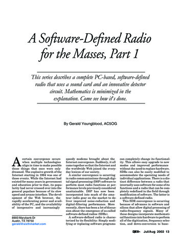
The Making of .OZYMANDIASSpecial Instructions: Placing LEDs 1 to 12How to determine the polarity ofthe 0805 LEDs?It can be difficult to find out the polarity ofthe tiny 0805 LEDs if you don't know whatto look for.The Lite-ON LEDs used in the OZY BOMare easy to determine the polarity.Looking on them under a magnifying glassyou can see that the LED dice (photo) isvisible and off-center from the body. Thisis the anode ( ) side which has to matchwith on the PCB.LED DiceThe ones which I am using have a littlemark printed on the bottom:CathodeAnodeCathodeAnode14Ver. 1.1; Okt. 28, 2008 DL6KBF
The Making of .OZYMANDIASItem RED15Ver. 1.1; Okt. 28, 2008 DL6KBF
The Making of .OZYMANDIASPana EZA-ST13AAAJ 22R100pFItem 8PositionReelR09R10R25R26Pana EZA-ST33AAAJ100R 100pFItem 9PositionReelR12R13Pana RP-Bus 8x10k EXBA10P103JItem 12PositionReelR16Pana RP-Bus 8x2.2kEXB-A10P222JItem 11PositionReelR11R1416Ver. 1.1; Okt. 28, 2008 DL6KBF
The Making of .OZYMANDIASPana RP-Bus 8x10k EXBA10P103JItem 12PositionReelR16Pana RP-Bus 8x2.2kEXB-A10P222JItem 11PositionReelR11R14Pana RP-Bus 8x100kEXB-A10P104JItem 10PositionReelR15R17R18R19R20R21R22R23R2417Ver. 1.1; Okt. 28, 2008 DL6KBF
The Making of .OZYMANDIASTantal 3216; 1uF/25VItem 3PositionReelC23C34Tantal 3216; 10uF/10VItem 4PositionReelC25C4118Ver. 1.1; Okt. 28, 2008 DL6KBF
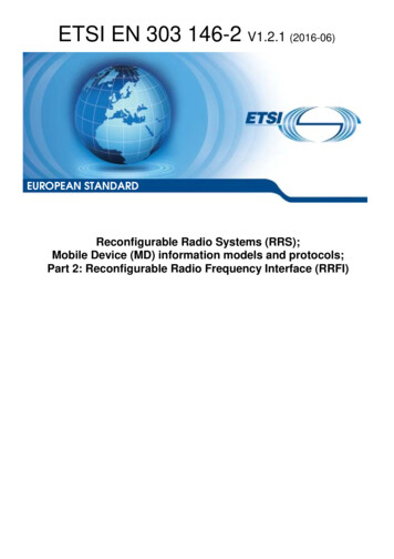
The Making of .OZYMANDIASDefault JumperSettings19Ver. 1.1; Okt. 28, 2008 DL6KBF
needles but household sewing machine needles are more readily available. So, during your next stop at the convenience store get yourself a pack of sewing machine needles. Microtex needles are to be preferred because they have a sharp tip. What do I do with them? The needles have a nice nickel plated surface.