Transcription
ETSI EN 303 146-2 V1.2.1 (2016-06)EUROPEAN STANDARDReconfigurable Radio Systems (RRS);Mobile Device (MD) information models and protocols;Part 2: Reconfigurable Radio Frequency Interface (RRFI)
2ETSI EN 303 146-2 V1.2.1 (2016-06)ReferenceREN/RRS-0246Keywordsinterface, mobile, SDRETSI650 Route des LuciolesF-06921 Sophia Antipolis Cedex - FRANCETel.: 33 4 92 94 42 00 Fax: 33 4 93 65 47 16Siret N 348 623 562 00017 - NAF 742 CAssociation à but non lucratif enregistrée à laSous-Préfecture de Grasse (06) N 7803/88Important noticeThe present document can be downloaded from:http://www.etsi.org/standards-searchThe present document may be made available in electronic versions and/or in print. The content of any electronic and/orprint versions of the present document shall not be modified without the prior written authorization of ETSI. In case of anyexisting or perceived difference in contents between such versions and/or in print, the only prevailing document is theprint of the Portable Document Format (PDF) version kept on a specific network drive within ETSI Secretariat.Users of the present document should be aware that the document may be subject to revision or change of status.Information on the current status of this and other ETSI documents is available .aspxIf you find errors in the present document, please send your comment to one of the following pportStaff.aspxCopyright NotificationNo part may be reproduced or utilized in any form or by any means, electronic or mechanical, including photocopyingand microfilm except as authorized by written permission of ETSI.The content of the PDF version shall not be modified without the written authorization of ETSI.The copyright and the foregoing restriction extend to reproduction in all media. European Telecommunications Standards Institute 2016.All rights reserved.DECTTM, PLUGTESTSTM, UMTSTM and the ETSI logo are Trade Marks of ETSI registered for the benefit of its Members.3GPPTM and LTE are Trade Marks of ETSI registered for the benefit of its Members andof the 3GPP Organizational Partners.GSM and the GSM logo are Trade Marks registered and owned by the GSM Association.ETSI
3ETSI EN 303 146-2 V1.2.1 (2016-06)ContentsIntellectual Property Rights .4Foreword.4Modal verbs terminology.41Scope .52References .52.12.233.13.2Normative references . 5Informative references . 5Definitions and abbreviations .6Definitions . 6Abbreviations . 74Introduction .85System 28.68.6.18.6.28.7Radio Computer Structure . 9URA . 11RF Transceiver . 11RF Interfaces . 11Radio Computer RF System Requirement Mapping . 11Notational Tools .12Notational Tool for Information Model Classes . 12Notational Tool for Interface Classes . 13Information Model for Radio Computer .13Radio Computer . 13Class Definitions for Information Model . 16Interface Definition .21Interface Overview . 21Spectrum Control Services . 24Overview on Spectrum Control Services . 24Messages for Spectrum Control Services . 24Power Control Services . 25Overview on Power Control Services . 25Messages for Power Control Services . 25Antenna Management Services . 25Overview on Antenna Management Services . 25Messages for Antenna Management Services. 26Tx/Rx Chain Control Services. 26Overview on Tx/Rx Chain Control Services . 26Messages for Tx/Rx Chain Control Services . 26RVM Protection Services . 27Overview on RVM Protection Services . 27Messages for RVM Protection Services . 28Class Definitions for Interface. 28Annex A (informative):Abstract Data Definitions .31Annex B (informative):RRFI Qualification Methods for Validation .34History .35ETSI
4ETSI EN 303 146-2 V1.2.1 (2016-06)Intellectual Property RightsIPRs essential or potentially essential to the present document may have been declared to ETSI. The informationpertaining to these essential IPRs, if any, is publicly available for ETSI members and non-members, and can be foundin ETSI SR 000 314: "Intellectual Property Rights (IPRs); Essential, or potentially Essential, IPRs notified to ETSI inrespect of ETSI standards", which is available from the ETSI Secretariat. Latest updates are available on the ETSI Webserver (https://ipr.etsi.org/).Pursuant to the ETSI IPR Policy, no investigation, including IPR searches, has been carried out by ETSI. No guaranteecan be given as to the existence of other IPRs not referenced in ETSI SR 000 314 (or the updates on the ETSI Webserver) which are, or may be, or may become, essential to the present document.ForewordThis European Standard (EN) has been produced by ETSI Technical Committee Reconfigurable Radio Systems (RRS).The present document is part 2 of a multi-part deliverable covering the Mobile Device (MD) information models andprotocols, as identified below:ETSI EN 303 146-1:"Multiradio Interface (MURI)";ETSI EN 303 146-2:"Reconfigurable Radio Frequency Interface (RRFI)";ETSI EN 303 146-3:"Unified Radio Application Interface (URAI)";ETSI TS 103 146-4:"Radio Programming Interface (RPI)".National transposition datesDate of adoption of this EN:30 May 2016Date of latest announcement of this EN (doa):31 August 2016Date of latest publication of new National Standardor endorsement of this EN (dop/e):28 February 2017Date of withdrawal of any conflicting National Standard (dow):28 February 2017Modal verbs terminologyIn the present document "shall", "shall not", "should", "should not", "may", "need not", "will", "will not", "can" and"cannot" are to be interpreted as described in clause 3.2 of the ETSI Drafting Rules (Verbal forms for the expression ofprovisions)."must" and "must not" are NOT allowed in ETSI deliverables except when used in direct citation.ETSI
51ETSI EN 303 146-2 V1.2.1 (2016-06)ScopeThe present document defines an information model and protocol for reconfigurable radio frequency interface forreconfigurable MDs. The work is based on the Use Cases defined in ETSI TR 102 944 [i.1], on the system requirementsdefined in ETSI EN 302 969 [1] and on the radio reconfiguration related architecture for mobile devices defined inETSI EN 303 095 [i.8].2References2.1Normative referencesReferences are either specific (identified by date of publication and/or edition number or version number) ornon-specific. For specific references, only the cited version applies. For non-specific references, the latest version of thereferenced document (including any amendments) applies.Referenced documents which are not found to be publicly available in the expected location might be found athttp://docbox.etsi.org/Reference.NOTE:While any hyperlinks included in this clause were valid at the time of publication, ETSI cannot guaranteetheir long term validity.The following referenced documents are necessary for the application of the present document.[1]2.2ETSI EN 302 969 (V1.2.1): "Reconfigurable Radio Systems (RRS); Radio Reconfiguration relatedRequirements for Mobile Devices".Informative referencesReferences are either specific (identified by date of publication and/or edition number or version number) ornon-specific. For specific references, only the cited version applies. For non-specific references, the latest version of thereferenced document (including any amendments) applies.NOTE:While any hyperlinks included in this clause were valid at the time of publication, ETSI cannot guaranteetheir long term validity.The following referenced documents are not necessary for the application of the present document but they assist theuser with regard to a particular subject area.[i.1]ETSI TR 102 944: "Reconfigurable Radio Systems (RRS); Use Cases for Baseband Interfaces forUnified Radio Applications of Mobile Device".[i.2]Recommendation ITU-T Q.1290: "Glossary of Terms used in the Definition of IntelligentNetworks".[i.3]ETSI TR 102 839: "Reconfigurable Radio Systems (RRS); Multiradio Interface for SoftwareDefined Radio (SDR) Mobile Device Architecture and Services".[i.4]IEEE 1900.4-2009 : "IEEE Standard for Architectural Building Blocks Enabling NetworkDevice Distributed Decision Making for Optimized Radio Resource Usage in HeterogeneousWireless Access Networks".[i.5]ETSI EN 303 146-1: "Reconfigurable Radio Systems (RRS); Mobile Device Information Modelsand Protocols; Part 1: Multiradio Interface (MURI)".[i.6]DigRFSM Working Group: "MIPI Alliance Specification for DigRFSM v4".[i.7]Recommendation ITU-T X.680: "Information technology - Abstract Syntax Notation One(ASN.1): Specification of basic notation".ETSI
6[i.8]ETSI EN 303 146-2 V1.2.1 (2016-06)ETSI EN 303 095 (V1.2.1): "Reconfigurable Radio Systems (RRS); Radio Reconfiguration relatedArchitecture for Mobile Devices".3Definitions and abbreviations3.1DefinitionsFor the purposes of the present document, the following terms and definitions apply:Application Processor (AP): part of mobile device hardware working under OS control and on which UserApplications, among others, are executedchannel: designated part of the information transfer capability having specified characteristics, provided at the usernetwork interfaceNOTE:It is the over-the-air wireless propagation channel which is used to convey an information signal fromtransmitter to receiver. This definition is specified in Recommendation ITU-T Q.1290 [i.2].Communication Services Layer (CSL): layer related to communication services supporting generic applicationsNOTE:A communication services layer supports generic applications like Internet access. In the presentdocument, it consists of Administrator, Mobility Policy Manager (MPM), Networking stack and Monitor.link: connection from one location to another through a given Radio Access Technology for the purpose of transmittingand receiving digital informationNOTE:Each Link is conveyed over a given Channel.Radio Application (RA): software which enforces the generation of the transmit RF signals or the decoding of thereceive RF signalsNOTE 1: The software is executed on a particular radio platform or an RVM as part of the radio platform.NOTE 2: RAs might have different forms of representation. They are represented as:source codes including Radio Library calls of Radio Library native implementation and Radio HALcalls;IRs including Radio Library calls of Radio Library native implementation and radio HAL calls;executable codes for a particular radio platform.Radio Computer (RC): part of mobile device hardware working under ROS control and on which RAs are executedNOTE:A Radio Computer typically includes programmable processors, hardware accelerators, peripherals, etc.RF part is considered to be part of peripherals.Radio Control Framework (RCF): control framework which, as a part of the OS, extends OS capabilities in terms ofradio resource managementNOTE:RCF is a control framework which consists of Configuration Manager (CM), Radio Connection Manager(RCM), Flow Controller (FC), Multiradio Controller (MRC) and Resource Manager (RM) which istypically part of OS.Radio Frequency (RF) transceiver: part of radio platform converting, for transmission, baseband signals into radiosignals, and, for reception, radio signals into baseband signalsRadio Operating System (ROS): any appropriate OS empowered by RCFNOTE:ROS provides RCF capabilities as well as traditional management capabilities related to management ofRP such as resource management, file system support, unified access to hardware resources, etc.ETSI
7ETSI EN 303 146-2 V1.2.1 (2016-06)radio platform: part of mobile device hardware which relates to radio processing capability, including programmablecomponents, hardware accelerators, RF transceiver, and antenna(s)NOTE:A Radio Platform is a piece of hardware capable of generating RF signals or receiving RF signals. Bynature, it is heterogeneous hardware including different processing elements such as fixed accelerators,e.g. Application-Specific Integrated Circuit (ASIC), or reconfigurable accelerators, e.g. FPGAs, etc.Radio Virtual Machine (RVM): abstract machine which supports reactive and concurrent executionsNOTE:An RVM may be implemented as a controlled execution environment which allows the selection of atrade-off between flexibility of base band code development and required (re-)certification efforts.reconfigurable Mobile Device (MD): Mobile Device with radio communication capabilities providing support forradio reconfigurationNOTE:3.2Reconfigurable Mobile Devices include but are not limited to: smartphones, feature phones, tablets, andlaptops.AbbreviationsFor the purposes of the present document, the following abbreviations SINRTRUMLURAURAIACKnowledgementACKnowledgement with ModificationApplication ProcessorApplication-Specific Integrated CircuitAbstract Syntax Notation OneBase-Band Integrated CircuitBlock Error RateCommunication Services LayerEuropean UnionMobile DeviceMobile Device Reconfiguration ClassMultiple Input Multiple OutputMobility Policy ManagerMUltiRadio InterfaceNegative ACKnowledgementOut Of BandOperating SystemRadio ApplicationRadio Access NetworkRadio Application PackageRadio Access TechnologyRadio ComputerRadio Control FrameworkRadio FrequencyRadio Frequency Integrated CircuitRadio Operating SystemRadio Programming InterfaceReconfigurable Radio Frequency InterfaceRadio Virtual MachineReceptionSignal to Interference plus Noise RatioTechnical ReportUnified Modeling LanguageUnified Radio ApplicationsUnified Radio Applications InterfaceETSI
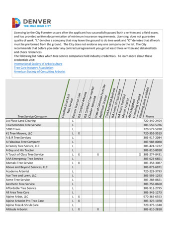
84ETSI EN 303 146-2 V1.2.1 (2016-06)IntroductionA reconfigurable MD is capable of running multiple radios simultaneously and of changing the set of radios by loadingnew Radio Application Package (RAP). All Radio Applications (RAs) are called Unified Radio Applications (URAs)when they exhibit a common behaviour from the reconfigurable MD's point of view [1]. In order to run multiple URAs,the reconfigurable MD will include Communication Services Layer (CSL), Radio Control Framework (RCF), RadioPlatform and 4 sets of interfaces for their interconnection.Figure 4.1: Four sets of interfaces for reconfigurable MDFigure 4.1 illustrates the reconfigurable MD architecture with the 4 sets of interfaces, i.e.: MURI for interfacing CSL and RCF [i.5]. RRFI for interfacing URA and RF Transceiver, which is the scope of the present document. URAI for interfacing URA and RCF [i.3]. RPI for allowing an independent and uniform production of RAs [i.3].The present document defines RRFI.ETSI
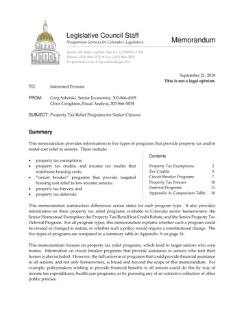
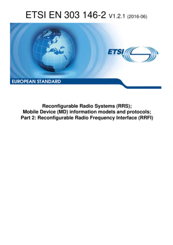
9ETSI EN 303 146-2 V1.2.1 (2016-06) interface IMURI interface IRRFIRadioComputer interface IRPI interface IURAIFigure 4.2: UML class diagram for RC interfacesFigure 4.2 illustrates UML class diagram for RC interfaces. The reconfigurable MD may be seen as a RC whereindividual URAs are engineered as software entities [i.8].The present document is organized as follows: clause 5 describes the system identification; clause 6 describes the notational tool for defining both information model classes and interface classes; clause 7 describes the information model for RC; and clause 8 describes the interface definition.While UML is used for defining the information model and protocol related to RRFI, other modelling languages couldbe used as well.5System Identification5.1Radio Computer StructureFigure 5.1 illustrates how URA and RF Transceiver interacts with each other using RRFI.ETSI
10ETSI EN 303 146-2 V1.2.1 (2016-06)Figure 5.1: Interconnection between URA and RF Transceiverusing RRFI for reconfigurable MDAs shown in figure 5.1, RRFI can support up to 5 kinds of services depending on the applicable MDRC [1].A Reconfigurable MD shall support all the services as required by the corresponding MDRC as shown in table 5.1 andfully detailed in clause 8 of the present document. In case that a reconfigurable MD supports multiple MDRCs, theconcerned reconfigurable MD shall support all the services as defined in table 5.1.Table 5.1: Required services of RRFI according to each MDRCMobile rol servicesPower NoNoTx/Rx ChainControl servicesRVM ProtectionservicesNoNoNoYesYesMDRC-2, MDRC-5YesYesYesYes(see note)MDRC-3, MDRC-6YesYesYesYesYesMDRC-4, MDRC-7YesYesYesYesYesNOTE:Among the various Tx/Rx Chain Control services, only the service related with Tx/Rx timing is required in thiscase.A corresponding summary of the services is given below. Spectrum Control servicesThese services are used to set up spectrum-related parameters such as carrier frequency, bandwidth, samplingfrequency, etc. that will be determined according to the URAs they are related to. Power Control servicesThese services are used to set up RF power-related parameters such as maximum transmit (Tx) power level, Txpower level per antenna, receive (Rx) gain, etc. Specific power schemes which have to be controlled accordingto the communication circumstance around the reconfigurable MD are also included in the Power Controlservices. Antenna Management servicesThese services are used to determine the antenna configuration. Antenna radiation pattern, antenna gain,antenna direction, sector configuration, polarization, frequency range, etc. are some factors to be considered inthe Antenna Management services.NOTE:Antenna Management services depend on the configurability of the antenna.ETSI
11 ETSI EN 303 146-2 V1.2.1 (2016-06)Tx/Rx Chain Control servicesThese services are used to provide parameters related to real-time control of the RF transceiver chain.Parameters to be controlled using the Tx/Rx Chain Control services include (but are not limited to) Txstart/stop time, Rx start/stop time, spectrum- and/or power-related values. RVM Protection servicesThese services are used to provide parameters related to the selection of RVM protection class. Parameters tobe controlled using the RVM Protection services include (but are not limited to) selection and/or request of RFprotection class as well as, RF Front-end indication of input data signals modification.The clauses 5.2 to 5.4 describe the components/entities shown in figure 5.1.5.2URARAs need to be subject to a common reconfiguration, multiradio execution and resource sharing strategy framework(depending on the concerned MDRC). Since all RAs exhibit a common behaviour from the reconfigurable MDperspective, those RAs are called URAs [i.8].5.3RF TransceiverRF Transceiver, which includes transceiver chain(s), is part of the radio platform in RC that transforms, in Tx mode, thebaseband signal to radio signal, and in Rx mode, the radio signal to baseband signal.5.4RF InterfacesThe RF Interfaces depicted in figure 5.1 denote digital interfaces which define the physical interconnections betweenbase-band and RFIC (Radio Frequency Integrated Circuit), for example, the DigRFSM specification defining theinterface between an RFIC and a BBIC (Base-Band Integrated Circuit) in a mobile device. RRFI defined in the presentdocument complements such RF interfaces by defining services which are required for reconfigurable MDs.5.5Radio Computer RF System Requirement MappingThe Radio Computer components above described shall support the RF system requirements shown in table 5.2 anddescribed in clause 6.5 of ETSI EN 302 969 [1].NOTE:The transceiver requirements defined in clauses 6.5.5, 6.5.6 and 6.5.8 of ETSI EN 302 969 [1] are notrelated to the RF Interface defined in the present document and therefore do not appear in table 5.2.Table 5.2: Mapping of RC Components to the system requirements described in ETSI EN 302 969 [1]Entity/Component/UnitUnified Radio ApplicationsSystem Requirements [1]R-FUNC-RFT-02RF e RF TSICommentsRadio Application selects a suitable number ofantenna inputs/outputs. The requirement isdescribed in clause 6.5.2 of ETSI EN 302 969 [1].The reconfigurable MD supports multiple RadioApplications using distinct frequency bands. Therequirement is described in clause 6.5.3 of ETSIEN 302 969 [1].RF transceiver manages input/output signalsfrom/to one or several Radio Applications. Therequirement is described in clause 6.5.4 of ETSIEN 302 969 [1].The RRFI provides a suitable interface for RFtransceiver configuration. The requirement isdescribed in clauses 6.5.1 and 6.5.7 of ETSIEN 302 969 [1].The RRFI supports a suitable selection of an RFprotection class. The requirement is described inclause 6.5.9 of ETSI EN 302 969 [1].
12ETSI EN 303 146-2 V1.2.1 (2016-06)6Notational Tools6.1Notational Tool for Information Model ClassesTable 6.1 shows a template for defining information model classes [i.4]. Each information model class is defined inclause 7.2 in accordance with the template shown in table 6.1.NOTE:ASN.1 is used throughout the present document for abstract type definitions; however, alternative waysare possible and are not excluded.Table 6.1: Template for defining Information Model ClassesClass Class name [(abstract class)] Description of the class DERIVED FROM List of super-classes ATTRIBUTES Attribute name [ optional ]Value type: Attribute value type Possible access: Attribute accessqualifier Default value: Default value Description of the attribute CONTAINED INCONTAINSSUPPORTEDEVENTS List of classes, whose instances may contain an instance of this class. If thisclass is an abstract class, that is, it is used for further refinement only and willnever be instantiated, then this list is empty. List of classes, whose instances may be contained in an instance of thisclass. Constraints used are: [*] - zero or more instances, [ ] - one or more instances, [ n ] - exactly n instances, [ m - n ] - not less than m and not more than n instances. List of event names that are detected by this class and lead potentially to acorresponding event report .Further details on the template in table 6.1 are given below. Class name is the name of the Class as it appears in the corresponding model. Additional information is alsoincluded in case the class in question has been specified as an abstract one. DERIVED FROM field identifies the super class of the class in case of sub-classing. ATTRIBUTES field describes the attributes that have been defined in the class. More specifically:- Attribute name identifies the name of an attribute, as it is included in the class definition.- Attribute value type holds the type of the attribute specified in Abstract Syntax Notation One(ASN.1). Details related to the ASN.1 module are specified in annex A of the present document.- Attribute access qualifier provides information about the level of accessibility of the attribute. Thismay include: 'Read', 'Write', 'Read-Write', 'Add-Remove' (for list-type attributes), 'Read-Add-Remove',and 'None' (for internal access only). CONTAINED IN field includes a list of classes whose instances may contain an instance of this class;containment is a strong aggregation relationship, that is, a contained instance is for its lifetime bound to itscontainer object and it is contained only in this one container. CONTAINS field provides a list of classes whose instances may be contained in an instance of the class inquestion. SUPPORTED EVENTS field includes a list of event names that are detected by this class and lead potentiallyto a corresponding event report.ETSI
136.2ETSI EN 303 146-2 V1.2.1 (2016-06)Notational Tool for Interface ClassesTable 6.2 shows a template for defining interface classes for RRFI. Each interface class for RRFI will be defined inclause 8.7 in accordance with the template shown in table 6.2.Table 6.2: Template for defining Interface ClassesClass Class name [(abstract class)] Description of the class OPERATIONS Operation name Return type: Operation return type Value type: Operation value type Description of the operation The template fields in table 6.2 are described below. Class name is the name of the Class as it appears in the corresponding model. Additional information is alsoincluded in case the class in question has been specified as an abstract one. OPERATIONS field describes the operations that have been defined in the class. More specifically:- Operation name identifies the name of an operation, as it is included in the class definition.- Return type identifies the type of return value at the corresponding operation. Details related to theASN.1 module are specified in annex B of the present document.- Value type identifies the access levels for member functions: public, private, protected.7Information Model for Radio Comput
reconfigurable MDs. The work is based on the Use Cases defined in ETSI TR 102 944 [i.1], on the system requirements . The software is executed on a particular radio platform or an RVM as part of the radio platform. . RCF is a control framework which consists of Configuration Manager (CM), Radio Connection Manager (RCM), Flow Controller (FC .