Transcription
José Raúl Machado-FernándezISSN 0121-1129eISSN 2357-5328Software Defined Radio: Basic Principles andApplicationsSoftware Defined Radio: Principios y aplicaciones básicasSoftware Defined Radio: Princípios e Aplicações básicasJosé Raúl Machado-Fernández*Fecha de Recepción: 29 de Septiembre de 2014Fecha de Aceptación: 15 de Noviembre de 2014AbstractThe author makes a review of the SDR (Software Defined Radio) technology, including hardware schemesand application fields. A low performance device is presented and several tests are executed with it using freesoftware. With the acquired experience, SDR employment opportunities are identified for low-cost solutionsthat can solve significant problems. In addition, a list of the most important frameworks related to the technologydeveloped in the last years is offered, recommending the use of three of them.Keywords: Software Defined Radio (SDR), radiofrequencies receiver, radiofrequencies transmitter, radiodevelopment frameworks, superheterodyne receiver, SDR hardware devices, SDR-Sharp, RTLSDR-Scanner.ResumenEl autor realiza una revisión de la tecnología Radio Definido por Software (SDR, Software Defined Radio)incluyendo esquemas de hardware y campos de aplicación. Un dispositivo de desempeño modesto es presentadoy varias pruebas son ejecutadas con él usando software de distribución gratuita. Con la experiencia adquirida,son identificadas oportunidades de empleo de SDR en soluciones de bajo costo que pueden resolver problemassignificativos. Además, se ofrece una lista de las librerías más importantes relacionadas con la tecnología en losúltimos años, recomendando el uso de tres de ellas.Palabras Clave: Software Defined Radio (SDR), receptor de radiofrecuencias, transmisor de radio frecuencias,librerías de desarrollo de radio, receptor superheterodino, dispositivos de hardware SDR, SDR-Sharp, RTLSDRScanner.*Instituto Superior Politécnico José Antonio Echevarría (ISPJAE) (La Habana, Cuba). m4ch4do@hispavista.comRevista Facultad de Ingeniería (Fac. Ing.), Enero-Abril 2015, Vol. 24. No. 38. pp. 79-96. pp. 79-9679
Software Defined Radio: Basic Principles and ApplicationsResumoO autor realiza uma revisão da tecnologia Rádio Definido por Software (SDR, Software Defined Radio) incluindoesquemas de hardware e campos de aplicação. Um dispositivo de desempenho modesto é apresentado e váriasprovas são executadas com ele usando software de distribuição gratuita. Com a experiência adquirida, sãoidentificadas oportunidades de emprego de SDR em soluções de baixo custo que possam resolver problemassignificativos. Ademais, se oferece uma lista das bibliotecas mais importantes relacionadas com a tecnologia nosúltimos anos, sendo recomendado o uso de três delas.Palavras Chave: Software Defined Radio (SDR), receptor de radiofrequências, transmissor de radiofrequências,bibliotecas de desenvolvimento de rádio, receptor super-heteródino, dispositivos de hardware SDR, SDR-Sharp,RTLSDR-Scanner.80Revista Facultad de Ingeniería (Fac. Ing.), Enero-Abril 2015, Vol. 24, No. 38
José Raúl Machado-FernándezI. IntroductionFrom the first wireless transmissions around 1890[1-3], radio transmission techniques have continuallyevolved, providing users the possibility to stayconnected with increasing transmission rates [4]. Thetriumphant radio era came first, in the mid-1930, at atime when limited band widths were used for analogvoice communications. Then, came the goldenera of broadcast transmission in the 50s [5] withanalogic television broadcasts that consumed morebandwidth but provided a rich customer experience.As computers became smaller and more powerful,reaching the 60s, they began to be useful as acommunication media for long distances, using bothwired connectivity via ARPANET[6] (which becamelater the Internet) and wireless satellite ALOHANET[7].Cell phones also emerged around this time[8], allowingusers to establish wireless voice communicationsfrom any public place or vehicle, although theoriginal mobiles were hard to operate and to travelwith, given their volume and weight. Many modernphones are now almost portable computers, providingaccess to both cellular networks and the Internet, andachieving wireless communications at speeds thatwere unimaginable a generation ago.To the continuous progress in communications, itfollows the advent of WLAN (Wireless Local AreaNetworks) that were originated in 1985 controlledby the United States Federal CommunicationsCommission (FCC). The organization put togetherthe not licensed spectrum in three different regionsto be used in the following applications: Industry(902-928 MHz), Science (2400-2483.5 MHz)and Medicine (5725-5850 MHz)[9]. However,the original IEEE standard for WLANs was notpublished until 1997[10]. Taking advantage of thesefreedoms in the spectrum, protocols such as WiFi andBluetooth proliferated and are now a vital part of anycorporative network.Despite the growth achieved by multiple technologies,an interesting and potentially problematic issuecommon to all mentioned devices is that their radiosand protocols are mostly hardware based. Therefore,reprogramming or reconfiguration options areminimal, at least regarding radio functions. This lackof flexibility is disturbing in the sense that if an erroroccurs in the hardware, firmware, or software thengenerally there is no reasonable way to correct theproblem: the built-in vulnerabilities are not easy toremove. In fact, these devices are commonly limitedin their functionality to the hardware componentsand cannot be reconfigured to perform other wirelessprotocols beyond what the hardware itself provides[11]. Precisely, the Software Defined Radio, subjectof this article, aims to provide a solution to manyof the problems described along with many otherbenefits.A. Software Defined RadioThe Software Defined Radio (SDR) is a designparadigm for wireless communications devices.Its creator, Joseph Mitola, defined the term in theearly90s as an identifier of a class of radios thatcould be reprogrammed and reconfigured throughsoftware[12]. Mitola envisioned an ideal SoftwareDefined Radio, whose physical components wereonly an antenna and an Analog Digital Converter(ADC) on the receiver side. Likewise, the transmitterwould have a Digital Analog Converter (DAC) and atransmitting antenna. The rest of the functions wouldbe handled by reprogrammable processors.As the idea conceived in the 90sis still notachievable, and a sit will not be likely for some time,the term SDR is used to describe a viable devicethat is primarily defined by software, but includessignificant hardware components. Even with thesecomponents, the SDR receiver is quite different froma traditional receiver.B. Motivation and ObjectivesSDR has evolved, like most technologies, frommilitary to civilian environments. The firstoperational SDR, known as Speakeasy [13] wasdeveloped by the United States’ Navy between 1991and 1995.Unfortunately, the application could notbe used with other than the hardware for which itwas conceived. Also, another negative issue was thefact that the device fully occupied the backside of atransport vehicle. His younger brother, Speakeasy II[14], achieved much greater success mainly due toRevista Facultad de Ingeniería (Fac. Ing.), Enero-Abril 2015, Vol. 24, No. 3881
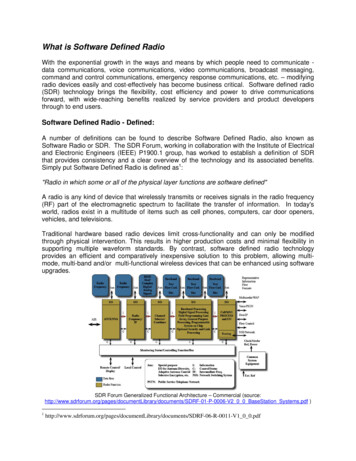
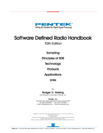
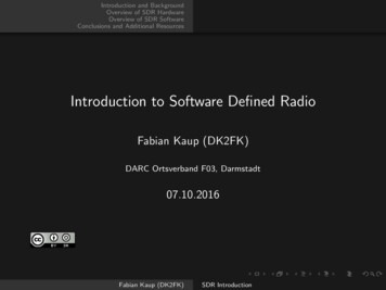
Software Defined Radio: Basic Principles and Applicationsadvances in electronics, wireless communicationscircuits, and reusable and modular programmingtechniques.A long way has been traveled from that first momentto the present. Today, both SDR software [14, 15] andhardware [16] are available at very low prices (in fact,most software implementations are free), which invitesto consider the introduction of the paradigm in radiosolutions. Thus, the author establishes as the article’sobjective to make a review of SDR technology,including hardware designs and application fields.In addition, he will show the operation of a softwaredefined radio device, identifying employmentopportunities at very low cost solutions that can solvelatent problems in common radio environments.II. SDR HardwareIn this section, a theoretical review of hardwaredifferences between traditional and SDR receivers isperformed at first, explaining also how the softwaredefined transmission takes place. Finally, a SDRdevice is shown setting the ground for the discussionof the technology’s applications in section 3.A. Traditional ReceiverA traditional or typical receiver, besides the classicdemodulation, performs three other operations: (1)carrier frequency tuning to select the desired signal,(2) filter to separate it from others received, and (3)amplification to compensate transmission losses.Moreover, an amplification step is commonly placedbefore the demodulation block to carry the signalto an acceptable level for the demodulator circuitry[17].Most traditional receivers have used conventionalheterodyne schemes for almost a century. Thesuperheterodyne internals blocks are shown inFig. 1 [18]. A basic understanding of the structureis necessary to distinguish this conception from thenew SDR receiver.82Fig. 1. Superheterodyne Receiver’s Internal Blocks.In the previous scheme, after the signal enters throughthe antenna, it is typically amplified by an RF stagethat operates only in the frequencies of interest region.Then, the signal is passed to the mixer which receivesthe local oscillator contribution by its other input. Thelocal oscillator’s frequency is set by the radio’s tuningcontrol [18]. The mixer is in charge of translating thesignal to the Intermediate Frequency (IF).Typically, the oscillator’s frequency is set to a valuethat ensures that its difference from the desiredsignal’s frequency is equal to the IF. For example,if someone would like to receive a FM station at100.7MHz and the IF were 10.7MHz, the localoscillator should be placed at 90MHz.The operationis known as downconversion.The next stage is a bandpass filter that attenuatesevery signal except a specific portion of thespectrum. The bandwidth of this stage limits the bandwidth of the signal that’s being received. Commoncenter frequencies for the IF stage are 455 kHz and10.7 MHz for commercial AM and FM respectively.Likewise, for commercial FM, the bandwidth isapproximately 100 kHz and for AM is above 5 kHz,consistent with the channel spacing that’s 200kHz forAM and 10 kHz for FM [19].At the end, the demodulator recovers the originalmodulating signal from the IF amplifier’s outputemploying one of several alternatives. For example,for AM an envelope detector is used, and for FM afrequencies discriminator [20]. Further processingof the signal depends on the purpose for which thereceiver is intended. In a common home radio, thedemodulated output is passed to an audio amplifierthat is connected to a speaker.Revista Facultad de Ingeniería (Fac. Ing.), Enero-Abril 2015, Vol. 24, No. 38
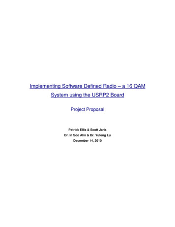
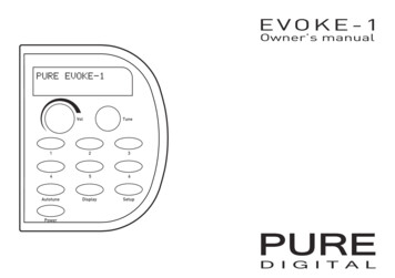
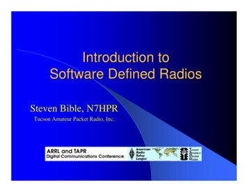
José Raúl Machado-FernándezB. SDR ReceiverFig. 2 shows the block diagram of a SDR receiver.At first, the RF tuner converts the analog signal toIF, performing the same operation that the first threeblocks of the superheterodyne receiver. Up to thispoint the two schemes converge [21].Fig. 2. Block Diagram of the SDR Receiver.Next, the IF signal is passed to the ADC converterin charge of changing the signal’s domain, offeringdigital samples at its output. The samples are feedto the following stage’s input which is a DigitalDown Converter (DDC). The DDC is commonly amonolithic chip and it stands as the key part of theSDR system. It consists of three main components:(1) a digital mixer, (2) a digital local oscillator, and(3) a Finite Impulse Response (FIR) low-pass filter.The components operation is similar to their analogcounterparts. The digital mixer and the local oscillatorshift the IF digital samples to baseband, while the FIRlow-pass filter limits the bandwidth of the final signal[21]. For the implementation of each of its parts, theDDC includes a high number of multipliers, addersand shift registers.Observe that the signals are transferred to theirbaseband equivalent at the digital mixer’s outputby the disintegration into the I and Q counter phasecomponents [20]. If the tuning of the digital localoscillator is modified, the desired signal can beshifted away or towards the point where it reaches0Hz. This variation, together with the bandwidthadjustment of the low-pass filter, defines which partof the reception is treated as a useful signal.Another procedure, known as decimation, iscommonly performed for reducing the samplingfrequency or sample rate. Thus, the new samplingfrequency in baseband results from the divisionof the original sampling frequency by an N factor,called decimation factor. The final sample rate canbe as little as twice the highest frequency componentof the useful signal, as proposed by the well-knownNyquist theorem [22]. Furthermore, practicalapproaches have shown that reduction can be appliedup to an extra 20% without significantly affectingthe quality of the result [19]. This can be expressednumerically as is done in equation 1.fb2 0.8fb fs/N (1)Where fb is the frequency at baseband, fs is thesampling frequency, N is the decimator factor and fb2is the new calculated baseband frequency after thedecimation is applied.Finally, the baseband samples are passed to theDigital Signal Processing (DSP) block, where tasksuch as demodulating and decoding are performed,among others.Revista Facultad de Ingeniería (Fac. Ing.), Enero-Abril 2015, Vol. 24, No. 3883
Software Defined Radio: Basic Principles and ApplicationsFig. 3. Block Diagram of a SDR transmitterThe PDS block can be implemented in an FPGA ifthe system is to be adapted to a specific application.However, PDS stages are commonly found within ageneral purpose computer in the form of specializedsoftware if versatility is to be added to the solution.C. SDR TransmitterAlthough the most common SDR devices arereceivers, the technology also includes transmissionschemes. The price of a SDR receiver can be as lowas 20 USD [16], while the cost of SDR transmitters/receivers typically exceeds 300 USD [23]. The SDRtransmitter’s structure is explained below.SDR transmitters receive a baseband signal as aninput, typically generated by a DSP step as it isshown in Fig. 3.The first block is a Digital Up Converter (DUC)which transfers the baseband signal to IF. The DACthat follows transform the samples to the analogdomain. Next, the RF converter shifts the signaltowards higher frequencies. Finally, the signal isamplified and directed to the antenna.Table 1Most relevant SDR Devices in the Market.CommercialNameMin.Freq. (MHz)Max.Freq. (MHz)RTL-SDR 28312417663,2Resolution ofthe ADC8Funcube Pro6417000,096Funcube Pro 0,19216No200600208Yes30030038004012Yes400-650USRP 11060006412Yes700MatchStiq30038002812Yes4500Within the DUC, the Interpolation Filter is responsiblefor raising the baseband signal’s sample rate tomatch the operating frequency of the componentsthat follow. Therefore, it performs the Decimator’sopposite operation in the receiver’s architecture.84BandwidthThen, the digital mixer and the local oscillator shiftthe samples to IF, the shift being controlled by thelocal oscillator.Revista Facultad de Ingeniería (Fac. Ing.), Enero-Abril 2015, Vol. 24, No. 38
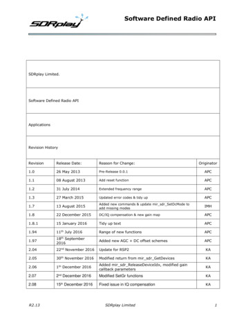
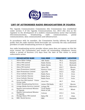
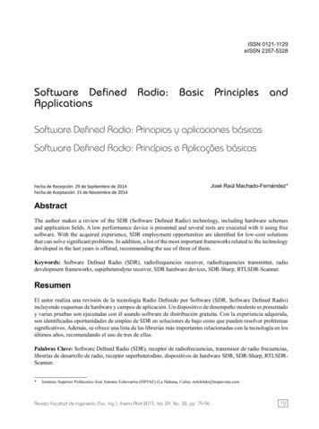
José Raúl Machado-FernándezD. RTL2831 DeviceOnce explained the structure of the SDR receiverand transmitter, it’s now the turn to introduce a SDRdevice. Later, in the section 3.3, some tests are carriedout exploiting its functionalities using free software.As one of the cheapest offers in the market,RTL2831SDR receiver from Teratec manufactureris an excellent choice for a first approach to thetechnology. It operates in the VHF and UHF bands,allowing the exploration of a considerable part ofthe spectrum used for national broadcasts in variousapplications. It delivers to the DSP stage a spectralwidth of 3,2 MHz at real time operation.Although it comes equipped with a quite smallantenna (customizable from 9 to 32cm), the RTL2831can be connected to other antennas with a betterperformance, adapted to the bands of intendedoperation. Moreover, the device has an USB 2.0 portfor communicating with the computer, consistent withthe spectral width that it handles. Devices able tomonitor higher band-widths are commonly connectedthrough a traditional network cable.Fig. 4. RTL2831 SDR Device.A. SDR FrameworksIn order to operate a SDR device, from a personalcomputer or from an FPGA running Digital SignalProcessing, software is needed for enabling theinteraction. However, before developing software,a framework must be created providing low-levelinterface functions. Several attempts have been madesince1980. Most major efforts are listed below.A small list of the most popular SDR devices in themarket is offered as a valuable reference in table 1[23]. Note that RTL2831 is the cheaper device. The Software Radio (1980-1985) [24] National Instruments – LabVIEW (1986 present) [25]III. SDR Software US Military – SPEAKKeasy I (1992-1995) [13] Massachusetts Institute of Technology –SpectrumWare (1994-1999) [26] US Military – SPEAKeasy II (1995-1997) [27] US Military – Joint Tactical Radio System(1997- present) [28] Trinity College – IRIS (1999 - present) [29] Vanu Software Radio (2001- present) [30] GNU Radio (2001 - present) [31] Flex-Radio SDR-1000 (2002-present) [11] Tsao, SDR Framework (2002) [32] Universidad de Kansas – Agile Radio (2003)[33]While the hardware components are essentials inthe SDR conception, the definition of the paradigmit-self points out the necessity of complementarydedicated software. In this section, a description ofthe main software tools that allows the SDR signalmanipulation is offered.Revista Facultad de Ingeniería (Fac. Ing.), Enero-Abril 2015, Vol. 24, No. 3885
Software Defined Radio: Basic Principles and Applications California Institute of Technology – CallRadio(2005 - present) [34] Rice – WARP (2006 - present) [35] High Performance SDR (2006 - present) [36] Virginia Tech – Open SourceImplementation (2006 - present) [37] Lyrtech – Small Form Factor SDR (2007 present) [38] Virginia Tech – Cognitive Engine (2007 present) [39] HYDRA (2007) [40]SCA P-HAL (2008 - present) [41] Microsoft – SORA (2009 - present) [42] Karlsruhe Institute of Technology – MATLAB /Simulink/ USRP (2009) [43] MathWorks – MATLAB / Simulink / USRP(2011 - present) [44]Though the above list is not complete, it illustratesthe increasing popularity of the SDR technology.Projects grouped by year are show in Fig. 5.Obviously, the number of emerging frameworks hasincreased since 2000.Fig. 5. Amount of Frameworks implemented by year.Among the published list, there are three librariesthat stand out for its frequent use in a great amountof the current research papers. The first of themappear in 2001 and it was designed exclusivelyfor Linux operative system, but its popularity [4547] has extended its usage also to Windows: GNURadio2001.The other two operate exclusively onWindows and are based on MATLAB mathematicalsoftware: Karlsruhe Institute of TechnologyMATLAB/Simulink/USRP2009 and MathWorksMATLAB/Simulink/USRP2011. Precisely together86with GNURadio, MATLAB is the most used supportin SDR investigations [48-50]. The Success of GNURadio and MATLAB mainly reside in the fact thatthey provide easy to handle tools for the manipulationof signals.The duration over time of the above mentionedSDR frameworks is illustrated in Fig. 6. As it can beseen, there is a growing tendency to stability in newprojects.Revista Facultad de Ingeniería (Fac. Ing.), Enero-Abril 2015, Vol. 24, No. 38
José Raúl Machado-FernándezFig. 6. Time Duration of SDR framework projects.B. SDR UsesOnce the SDR device is in communication withthe personal computer, one can start looking foruses of the technology, offering specific solutions.The concept of unified platform and the ability tocorrect errors in real time are the classic applicationsof SDR. However, studies have identified othersignificant applications, such as: Dynamic SpectrumPositioning, Opportunity Driven Multiple Access(ODMA), Spectrum Regulation and Cost Reduction(some SDR implementations are more cheaper thanits analog counterpart) [51].A little beyond its traditional applications, theSDR philosophy begins to dawn on high-impactareas within telecommunications. This is the caseof Driver Assistance [52], GPS signals’ Reception[53], HF Propagation Analysis [54], Interpretation ofCellular Technology Emissions [55-57] particularlythe OFDM modulation [58], and the Identification ofRadio Frequency Emissions [59].In other visionary fields, SDR experiments haveprovided encouraging results that motivate tocontinue the investigations. Potential applicationsare being found in areas as diverse as prototypesdevelopment [60], microscopic investigations of thestrength of the magnetic resonance [61], aviationtests [62], evaluation of multi-path communications[40], broadcast transmissions in multi-media mobileenvironments [63], cooperative wireless networksdiversity [64], crossings prototypes between wirelessnetworks layer, quantum optical communications andparticularly in cognitive radio research [65-68].Revista Facultad de Ingeniería (Fac. Ing.), Enero-Abril 2015, Vol. 24, No. 3887
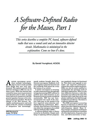
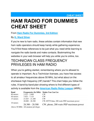
Software Defined Radio: Basic Principles and ApplicationsFig. 7. Real time spectrum visualizationC. Employment OpportunitiesMany of the applications previously described areonly available to large corporations and universitieswith high amounts of money dedicated to research.However, there are some low-cost solutions that canbe achieved with the RTL2831 or another similardevice using free software. In this section, severalfree downloaded softwares are presented, togetherwith some solutions that can be materialized orstudied with them. Every one of the provided figureswas obtained by running the softwares on Windows7 and 8.Understanding how SDR-Sharp works, someapplications can be identified. They are shown below:1) SDR-SharpThe first software is called SDR-Sharp [14] anddisplays in real time all the readings that is capableto generate the SDR device, which it translates to 3.2MHz in the case of the Teratec RTL2831. As shownin Fig. 7, it offers of 4 main windows to the user.The top one shows the spectrum displayed in realtime, in which three FM radio stations are visible inthe selected example. The next window, known aswaterfall chart, illustrates the signal s time behaviorshowing the most intense emissions in warmer colors.88The two lower windows are in charge of plotting theselected bandwidth inside the full spectrum displayedin the top window. To the left, the IF spectrum can beperceived. To the right, the frequency distribution ofthe voice demodulated signal is illustrated. In addition,the transmission’s acoustic content can be heard if aspeaker is connected to the computer. Obviously, inthe example above, the demodulation scheme useda FM demodulator. In addition, the software allowsdemodulation of the AM (Amplitude Modulation),CW (Continuous Wave), USB (Upper Side Band),LSB (Lower Side Band) and DSB (Double SideBand) signals. Cheap Radio Receiver: A general purposecomputer may become a cheap radio receiverif a SDR device is connected to it. SDR-Sharpworks well on single core 2GHz computerswith at least 1GBof RAM. However, there aresome operations that consume more resources.Revista Facultad de Ingeniería (Fac. Ing.), Enero-Abril 2015, Vol. 24, No. 38
José Raúl Machado-FernándezFig. 8. Interference generated by an RF transmission. Interference Detection: Not all emissionsare kept within the frequency regionspecifically conceive for them. Some deviceslet escape signals, resulting from undesiredintermodulation, which can interfere with otherradio users. As it is visible in Fig. 8, SDR-Sharpis a very useful tool when is necessary to detectan interference. Spectrum Relocation: A SDR receiver allowsexploring a wide range of frequencies so thatnot used or not assigned spaces can be found,as well as frequencies with very low access.This type of studies allows for transmissionrelocation, optimizing the consumed bandwidth. SpectrumRegulationandAutomaticTransmission’s Identification: Unfortunately,radio users do not always maintain discipline.Sometimes emissions occur in unauthorizedbands. Real time monitoring is achievabletrough SDR-Sharp. In addition, such a versatiletool induces the implementation of Systemsfor Automatic Transmission’s Identification.Emissions can be distinguished not only byits bandwidth, but by its cyclic variation andspecific characteristics such as the tail’s shape ofthe signal. Note that the automatic identificationcannot be executed directly with SDR-Sharp.New software needs to be created.Fig. 9. RF transmissions distinctive features. Checking Repeaters Systems: If the powerreceiver from several repeaters is periodicallymeasured in a common geographic point,damage, interference or disruptions can bedetected. Similarly, if a SDR transmitter wasavailable, or a conventional radio device with asimilar functionality, low rate or probably downsites availability could be checked. Furthermore,with the employment of frameworks as thementioned above it’s possible to automate theprocess.2) RTLSDR ScannerAnother very useful software is RTLSDR Scanner [15]which has the characteristic of being cross platformas it has been tested on Windows 7 and 8, Ubuntu12 and 13 and Macintosh Systems like Leopard andMountain Lion. In short, the application is a spectrumanalyzer that performs consecutive scans and allowsto gather data and to make comparisons. UnlikeSDR-Sharp, it does not operate at real time.Fig. 10 shows a measurement made with RTLSDRScanner. In it, the computation of the receivedpower’s average after performing several scans overa1 MHz bandwidth is revealed. Note that a specificarea may be selected if the user wishes to obtainnumerical values for the Maximum Power, LowPower and Average Value.Revista Facultad de Ingeniería (Fac. Ing.), Enero-Abril 2015, Vol. 24, No. 3889
Software Defined Radio: Basic Principles and ApplicationsFig. 10. Spectrum Analyzing with RTLSDR Scanner.The plotted results can be saved in different formatsand comparisons can be performed over them toanalyze the measurements. One of the comparisons isshown in Fig. 11 where data from consecutive scansis plotted. The colored area represents the signal’svariation. For example, the peak to the extremeleft is colored, which means that the maximum isnot constant but appears at intervals in this area.By contrast, the peak to the extreme right is notcolored, indicating that the local maximum hasn’tfall throughout the all observation period.Fig. 11. Plotting the difference between consecutives scans.Taking advantage of the benefits offered by RTLSDRScanner, some applications can be identified. Theyare show below: 90Measurement of the repeaters’ electricalparameters: RTLSDR Scanner allows checkingif the signal parameters offered by manufacturersare actually implemented by their equipment.Transmitted power and frequency deviation canbe easily checked, as well as the appearanceof harmonics frequency bands near to the oneintended for the communication.Noise Characterization by Bands: By exploringthe spectrum, qualified personal may analyzethe noise level of each band obtaining as aresult the possibility of making adjustments inthe propagation calculation methods. Spectrum Intruders Identification: Scanningsilence zones, unauthorized transmissions canbe detected.3) SDR for AndroidOne of the platforms for which SDR applicationshave been developed is Android. The software SDRTouch turns the phone in to a SDR receiver whoserange fluctuates between 50MHz and 2 GHz in AM,FM and SSB depending on the used hardware [69].There is also another software called Pocket HAMBands Transceiver who allows the remote listeningof SDR receivers.Revista Facultad de Ingeniería (Fac. Ing.), Enero-Abril 2015, Vol. 24, No. 38
José Raúl Machado-FernándezFig. 12. SDR Touch Visual Interface.4) SDR in the WebSDR’s perspectives in the future are many andvaried, but its application is particularly importantwhen Internet connected systems are brought intoconsideration. From this point of view, there are twofundamental approaches:1. Transmission over Internet of own SDR signals.2. Free access to foreigners SDR in remotelocations.For the transmission of a local own signal (approach1) the software rtl tcp may be used. With two PCs, ahub and SDR RTL 2831 the possibility to visualizedata received through the network was verified.However, when a laptop was added as a third activeelement, the disadvantage of the scheme becameevident: only one remote host can receive the signal ata given time. There are two solutions to the problem: Place several SDR devices in a centralizedserver so each remote may have access to adifferent one. This can be made because of thelow prices of the SDR hardware available onthe market. However, note that the alternativerequires some centralized service that shouldact as a judge and rule the access to variousdevices connected. Establish a Linux server responsible forhandling requests to a single device. Thisapplication already exists.Both options are viable, being the selectionconditioned by the necessities of each particular user.However, if the conditions are given, the second-oneis recommended over the first.Regarding the free access to foreigners SDR inremote locations (approach 2), it needs to be letclear that this alternative is equally or more valuablethan the previous. Worldwide, there are a lot ofSDR devices ruled by amateur users and nonprofitassociations. The geographical location of all 79stations is provided in Fig. 13 [70].As the reader may notice, the majority of the receiversare located in Europe, although there are stations inall continents. The operating bands and the signal’squality offered by the deployed devices differ fromone location
A. Software Defined Radio The Software Defined Radio (SDR) is a design paradigm for wireless communications devices. Its creator, Joseph Mitola, defined the term in the early90s as an identifier of a class of radios that could be reprogrammed and reconfigured through software[12]. Mit