Transcription
Implementing Software Defined Radio – a 16 QAMSystem using the USRP2 BoardProject ProposalPatrick Ellis & Scott JarisDr. In Soo Ahn & Dr. Yufeng LuDecember 14, 2010
Project SummarySoftware Defined Radio takes what used to be physically ingrained within the radio andprovides a variety of hardware and software alternatives that add to it more flexibilityand functionality. This project looks to implement a 16QAM communication systemusing a baseband receiver and transmitter and two USPR2 boards. It will show thebenefits of Software Defined Radio (SDR) and will demonstrate the power, flexibility,and advantages that it gives the designer through the ease of modification that itprovides. This project does, however, require a great amount of new, unfamiliarsoftware which may prove to be one of its biggest challenges.Complete DescriptionBackgroundSoftware Defined Radio, as defined by the SDR Forum is a “Radio in which some or allof the physical layer functions are software defined.” Together, the above componentswill allow the realization of a SDR 16QAM communication system. Each component willbe discussed in detail and then the overall system will be explained in the process.GoalsThe progressive goals of the project are listed as follows.1.Design16QAM transmitter and receiver modules using GNU Radiocompanion (no USRP2 board or noise used at this point).2.Add simulated noise resources to the communication channel within the priorsystem to introduce fading and multipath effect.3.Design Decision Feedback Equalizer system to fully recover the transmitteddata at the receiver end.4.Explore the capabilities of GNU radio and boards by small side projects suchas an FM receiver in order to more fully encompass the capabilities and spanof SDR.
Equiptment ListThe entirety of this project will consist of the following software and equipment:1.Two USRP2 Boards – Offers a Xilinx Spartan 3 2000 FPGA,14-bit AD and16-bit DA converters, digital up/down converters, gigabit Ethernet interface,external memory, and SD card.2.BasicTX and Basic RX Daughterboards – Gives access to all of the signalson daughterboard interface and provide AD/DC outputs with no mixers, filters,or amplifiers.3.GNU Radio Companion – an open-source software development similar toSimulink in nature whose applications are written in Python and the signalprocessing paths implemented in C .4.Python Interpreter – software to write and debug code written in Python.5.Ubuntu – Version 8.04 or greater will provide the operating system requiredfor GNU Radio and the USRP2 to function properly.USRP2The USRP2 is a high speed Ethernet-based board that is specifically built by EttusResearch for software radio. Drivers are open source and there is a variety of freesoftware to integrate such software toolkits as GNU Radio. The USRP2 is built withSDR in mind as it is made to be highly flexible with designer’s specific needs regardingfrequency bands, connectors, and different daughterboards.Features: Xilinx Spartan 3-2000 FPGA Gigabit Ethernet interface Two 100MS/s, 14 bit, AD converterso LTC2284o 72.4dB SNR and 85dB SFDR for signals at Nyquist Frequency Two 400MS/s, 16 bit, DA converterso AD9777o 160 MSPS w/o interpolationo Up to 400 MSPS with 8x interpolation
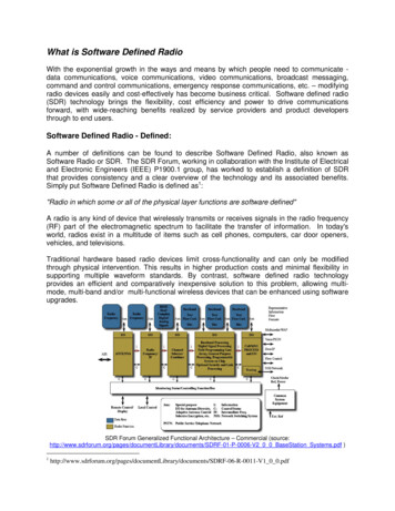
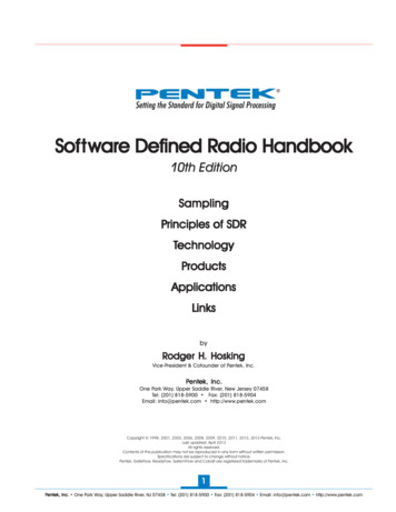
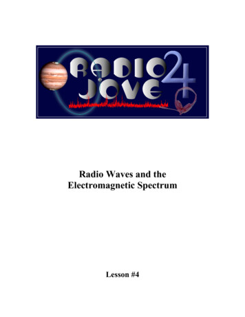
SD card reader MicroBlaze Processor Core aeMB software implementation of MicroBlazeBasicTX and BasicRX DaughterboardsThe BasicRX board has 4 subdevices. Subdevice A is a real signal on antenna RXA,subdevice B is a real signal on antenna RXB, subdevice AB is a quadrature subdeviceusing both antennas (IQ), and subdevice BA is a quadrature subdevice using bothantennas (QI). The Basic TX board is the exact same but with “TX” instead of “RX.” Theboards do not allow any tuning of elements or gains, but the ability to up-convert signalsgreater than the Nyquist rate of the DAC can be done with aliasing. External RFHardware must be used with these boards and the TVRX antennas.Features: Serve as RF front end Modulates output signal to higher frequency Takes away input signal carrier frequency BasicRX is a 1-250MHz Receiver BasicTX is a 1-250MHz TransmitterGNU Radio, Python, and UbuntuGNU radio is a free software toolset for building and implementing SDR. It is a signalprocessing package which provides a variety of signal processing blocks as well as theability to develop ones own blocks. The signal processing blocks are written in C andare accessed, called, and implemented by Python; much in the manner an m-file wouldcontrol a Simulink file. GNU radio, when implemented with the USRP2 must be on aLinux-based system.High Level Block DiagramFigure 1 shows the high level over-all system block diagram that shall be implementedwithin the final objective. As can be seen, the entire communication system is softwarebased and only the ADC/DAC and RF are hardware-based. The 16QAM system, or
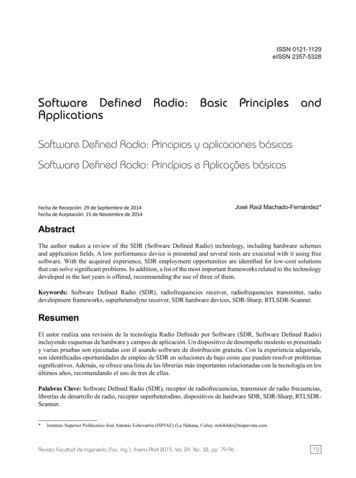
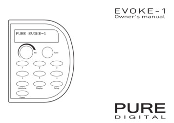
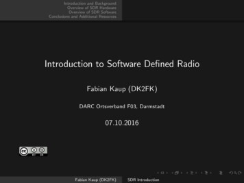
other systems, can be quickly changed through programming the Spartan3-2000 FPGAdevice on a USRP2 board. Figure 1 clearly points out the relationships between theUSRP2, Daughterboards, and GNU Radio. GNU radio initiates the interfacing betweenthe USRP2, daughterboards, and the signal processing that it performs. Thedaughterboards perform converting (up or down as needed) and the antenna transmitsor receives the desired information.Figure 1 – High Level Block Diagram16 QAM Communication SystemFigure 2 shows the general flowchart of a 16QAM system which shall be implementedon the USRP2 board via GNU Radio Companion. The 16QAM transmitting andreceiving systems are shown on the top and bottom of Figure 2 respectively. The RRCblocks represent root raised cosine filters and the DFE is a decision feedback equalizer.The transmitting side works as follows: The 16QAM mapper takes in the data andselects 4 bits. Two sets of 2 bits are selected and are mapped to one of four values: -3,-1, 1, or 3. One symbol contains the I component and the other the Q component, thevalues of which are determined from the gray coding scheme. Each symbol stream issent through the RRC block to decrease bandwidth. They are then used to modulatetheir respective carrier waveforms and added to form the transmitted signal.At the receiving end, the transmitted signal is split once again into its I and Qcomponents and the modulating signals are brought back to baseband and filtered bythe RRC filters. A decision feedback equalizer (DFE) is then used to recover the signal
and compensate for any noise, fading, or multipath effect that can be added in thechannel during transmission. The signal is then decoded through a look-up table (LUT)and the original data is received.Figure 2 – 16QAM Block DiagramSystem SpecificationsThis system shall able to transmit and receive within the frequency range of the BasicTX and RX daughterboard, which is 1 MHz to 250 MHz. The generated and receivedsignals shall use the DAC and ADC respectively; on the USRP2 board. The signal shallthen be processed inside the 16QAM system. The carrier frequency fc shall be at least 4times smaller than the USRP2 overall system clock, which is 100 MHz. As a result the fcmaximum value shall be 25 MHz.
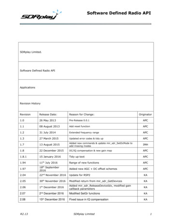
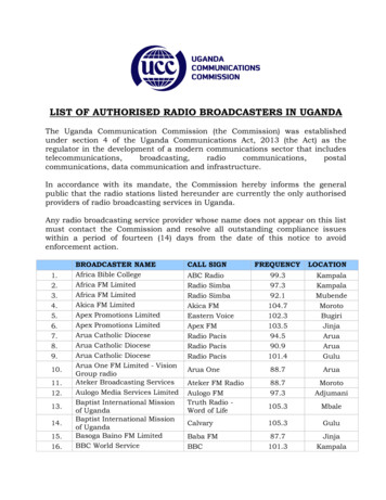
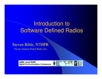
The 16QAM system has the following constraints: The sampling frequency of thereceiving system shall be greater than or equal to twice the bandwidth, or twice fc tosatisfy Nyquist’s Theorem. The QAM system shall minimize bit error rate. Once successhas been reached on transmitting a variety of signals (random bit stream, picture,audio), flexibility and system performance shall be tested by introducing multipatheffects.As familiarity increases with GNU radio, Python, the USRP2 and its daughterboards,more specifics in regards to particular bandwidths, baud rates, ACD/DAC conversions,and power, more detail-oriented objectives will be able to be made.Preliminary Work:Tutorials:GNU Radio Companion (GRC):GRC is an open source program that consists of signal processing blocks to allow easyconstruction of various systems using the GNU Radio libraries. In order to familiarizewith this program, several tutorials provided by Sharlene Katz were completed. Figure 3shows the end product of one tutorial in which an AM receiver was constructed using afile source as the input. Variable sliders are used to tune to the desired frequency andadjust the volume. Various parameters such as sampling rate and filter cutoff frequencycan be set as desired. This demonstrates power of SDR.
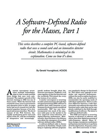
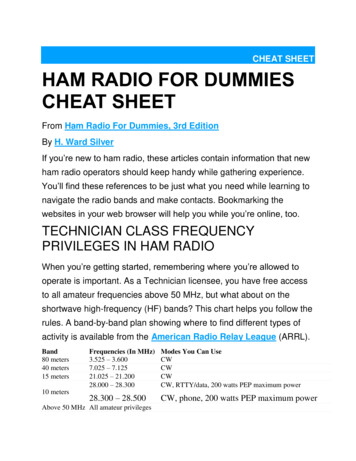
Figure 3 – Flow Graph for an AM ReceiverThe FFT outputs of the file source and the filtered signal for the selected frequency areshown in Figure 4 and provide a real time simulation visual for the user.Figure 4 – FFT Sink Outputs of AM Receiver Flow Graph
Python:Since Python programming language is used to link the GNU Radio signal processingblocks and will be have to be used to create customized blocks, a simple tutorial wascompleted. The tutorial constructed a system which produced a basic dial tone usingtwo sinusoids of separate frequencies. The code is shown in Figure 5 and is equivalentto a flow graph sending two sinusoids to an audio sink in GRC.Figure 5 – Python File for Generation of a Dial Tone
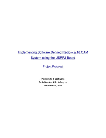
16QAM System Construction & SimulationIn the progress of completing goal number one of simulating the 16QAM system with nonoise or USRP2 board, the system in Figure 6 has been created in GRC. The purposeof this system is to show that a stream of random binary data can be successfully sentand received using the 16QAM method. Although this system is not yet functioningcorrectly due to an unknown error created in the QAM Demod block, the input data andthe constellation plot at the output of the QAM Mod block are shown in Figure 7.Figure 6 – Flow Graph of the 16QAM System without Noise
Figure 7 – Random Source Binary Data and 16QAM ConstellationThe plots in Figure 7 demonstrate how the transmitting signal can be created with theuse of only one main block. The block contains the creation of the I and Q componentsand the filtering process using RRC filters. The small imperfections in the constellationplot are due to this filtering.Preliminary ScheduleDatesTask1/20 - 1/261/27 - 2/22/3 - 2/92/10 - 2/162/17 - 2/232/24 -3/2Create and simulate a 16 QAM system using GNU radio companionContinue creating systemIntroduce fading and multipath effect. Create DFE for signal recoveryContinue creating recovery systemContinue creating recovery systemContinue creating recovery systemExplore the USRP2 board by creating simple FM receiver and othersystemsContinue exploring USRP2 capabilitiesContinue exploring USRP2 capabilitiesContinue exploring USRP2 capabilitiesTest the 16 QAM system by sending various data between two USRP2boardsSystem debugging and documentationSystem debugging and documentationSystem debugging and documentation3/3 - 3/93/10 - 3/113/21 - 3/233/24 - 3/303/31 - 4/64/7 - 4/134/14 - 4/204/21 - 4/27
4/28 - 5/3Presentation preparation and practiceNote: Not shown on the Preliminary Schedule are our planned efforts over winter breakto complete two tasks. One is the identification of the parameters given to us to use thesignal processing C blocks in GNU radio. No documentation exists to tell us whatthese parameters represent and an in depth look at the Python, then C files alongwith communication textbooks will hopefully allow us to identify these parameters.Secondly we will be researching the receiver system – primarily the Decision FeedbackEqualizer portion in an effort to combat the complexity and learning curve whenimplementing it in the spring semester.
Bibliography[1] Couch, Leon W. Digital and Analog Communication Systems. Upper Saddle River,NJ: Pearson Prentice Hall, 2007. Print.[2] "Exploring GNU Radio." The GNU Operating System. Web. 11 Nov. 2010. -gnuradio.html .[3] Hanzo, Lajos, Thomas Keller, Soon Xin. Ng, and William Webb. QuadratureAmplitude Modulation: from Basics to Adaptive Trellis-coded, Turbo-equalisedand Space-time Coded OFDM, CDMA and MC-CDMA Systems. [Piscataway,NJ]: IEEE, 2004. Print.[4] Katz, Sharlene. "CSUN/EAFB SDR Project." California State University, Northridge.Web. 07 Oct. 2010. http://www.csun.edu/ skatz/katzpage/sdr project/sdrproject.html .
Software Defined Radio, as defined by the SDR Forum is a “Radio in which some or all of the physical layer functions are software defined.” Together, the above components . The tutorial constructed a system which produced a basic dial tone using two sinusoids of separate fre