Transcription
Product CatalogWater Source Heat Pump Air to Water/Packaged UnitGEHC 012 060Cooling: 4.1 16.7kWHeating: 5.1 20.9kW50HzAugust 2013GEHC-PRC001-EN
Features and BenefitsOverviewImagine a comfort system with high efficiency, low operating noise and smart controls while Tranerecognized those with customers concern. Therefore, Trane water source heat pump functions tobe a comfort solution as with an effective system.The entire range of GEHC (Packaged Water Source Heat Pump) has been designed withoutstanding quality in mind: Ease of maintenance High efficiency Low operating noiseThe use of coaxial coil achieves maximum heat transfer and minimum fouling as well as scaling.The full range GEHC is applicable to small or medium sized buildings, schools, industries, healthcare centers and commercial applications.Flexible ApplicationThe GEHC has flexible configuration in system design. Providing front and side supply airconfigurations are significantly convenient for local installation. The hanging brackets reside in eachcorner of unit. This particular design eliminates extra clearances required to the product besides ofquick installation.Accurate ControlAdvanced microprocessor functions unit control with visibility of LCD controller or in peersconfiguration for system expansion.Noise ControlState-of-Art acoustical design makes GEHC in minimum noise during operation.Low InvestmentWith water source heat pump system, mechanical room could be saved for units allocation, henceless piping design is required. Therefore, initial cost of investment can be reduced significantly.Easy Retrofit and Individual OperationWater source heat pump system offers flexibility for speculative buildings. Extended units can beinstalled and connected to an existing system for additional spaces. This also gives space for meterdevices to individuals who pay electricity bills independently. Furthermore, one unit’s failure willnot affect the operation of the whole system.2GEHC--PRC001-EN
Model Number DescriptionsG13E2H3C40516276819M O 1 1 L R E10 11 12 13 14 15 16Digits 1-2Product TypeGE Packaged UnitDigit 3H Horizontal ConfigurationDigits 4Development SequenceCDigits 5-7Unit Size012 024 030 036 048 060Digit 8Voltage/Hertz/Phase6 220 240V/50Hz/1Ph (012-030)9 380 415V/50Hz/3Ph (036-060)Digit 9Thermostat1 With LCD Thermostat (Applicable Single or Modular Configuration)2 Without LCD Thermostat (For Modular Configuration Only)Digit 10ControllerM Microprocessor ControlDigit 11Refrigeration CycleC CoolingO Heat PumpDigit 12System Application1 Water Loop (Cooling Tower System)2 Ground Water (Opened System)3 Ground Loop (Closed System)Digit 13Blower Configuration1 Normal Static PressureDigit 14Supply Air ArrangementL Left SideT FrontDigit 15Return Air ArrangementN w/o FilterR w/6 mm Nylon filterT w/12 mm Aluminum filterDigit 16RegionE ExportGEHC-PRC001-EN
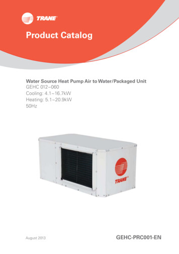
System OverviewTypical Diagram of Water Source Heat Pump System for Commercial ApplicationCooling TowerWater pumpPlate heat exchangerBoilerWater-to-water WSHPSplit type WSHPPackaged water-to-air WSHPNote: Above diagram was sketched for reference only. Please consult designers for professional advice.4GEHC--PRC001-EN
General DataModelCooling CapacityHeating CapacityPower 786871060kW5.149.3411.6312.6217.0220.9021001845220 240/1/50930380 1A5.72W/W3.883.66EERGEHC0603539QTYRunning CurrentGEHC04813974TypeInput HzNominal Coaxial 741.071.251.371.731.93Dimensions 0x520Return Air Collar y Air Collar r Dimensions(LxW)mm348x302Operating Weightkg68Condenser Water Flow RateWater Pressure DropRefrigerantRefrigerant ChargeExternal Static Pressure With Nylon FilterTypeR410 A508x33072528x42283130Pa2030Water ConnectionsInch1/2" FPT3/4" MPTDrain Connectionmm748x42214214816(OD)Notes:1.The unit has been tested in cooling tower condition of GB/T 19409-2003 requirement.2.Cooling conditions:Indoor entering air dry/wet bulb temperatures are 27 /19 ; entering and leaving water temperatures are 30 /35 .3.Heating conditions:Indoor entering air dry/wet bulb temperatures are 20 /15 ; entering water temperatures are 20 .5GEHC-PRC001-EN
Performance Data - Variable GEHC0606NominalAirflowNominal WaterFlow .463.78Cooling(EDB 27 /WB19 )EWT Cooling Capacity Input Power(kW)(kW)Heating(EDB 20 )EWT Cooling Capacity Input GEHC--PRC001-EN
Correction Factors and Electrical DataCorrection Factor for AirflowAirflowCoolingSensible Load (kW)0.890.920.950.9711.051.081.1Total Load 10%115%120%Input Power (kW)0.960.970.980.9911.021.031.04Total Load0.970.980.990.9911.011.021.03HeatingOutput Power (kW)1.031.021.021.0110.980.980.97Correction Factor for Entering Air TemperatureCoolingEntering WBTemperature ( )101517192324Total Load Input 31.04HeatingSensible Capacity Factor CorrespondingEntering DB Temperature ( /27//1.1310.730.532///1.210.940.72Entering DBTotal Load Input PowerTemperature(kW)(kW) 1.06Electrical C048GEHC0607Voltage/Hz220 240V/50Hz220 240V/50Hz220 240V/50Hz380 415V/50Hz380 415V/50Hz380 1111MinimumMaximum Recommended Maximumcrosscircuitfusefusesection ofcurrentspecification specificationcopper .082.52.542.544GEHC-PRC001-EN
DimensionsABMJSupply AirWater InletKAWater OutletLDCICable Access HoleGDrain Pipe ConnectionHReturn AirF37,0View ATop ViewMJWater OutletKReturn AirEI50,0GCable Access HoleWater InletDrain Pipe ConnectionH62,0FView ASide View(For GEHC012 01535622930GEHC--PRC001-EN
InstallationsClearanceAccess to the unit for service purposes should be provided at installation. All 1/2 through 5 tonconfigurations require an 18" (457mm) surround clearance from other mechanical and electricalequipment (where shown) to enable panel removal from the unit for service/maintenance ability.Some local codes may require a greater service clearance than listed here. Check all coderequirements prior to unit installations.Water Pipes Connection1. Installation of water pipings should be designed in the way that winding upward and downwardplacement are reduced as much as possible.2. Flexible hose is recommended to be installed between unit and system piping. This will reducevibration and prevent pipeline leakage effectively.3. It is recommended to install shut-off device on the supply and return of the system, the unitmay be isolated during service or maintenance situation.4. Keep sufficient water pressure in the system to ensure water flow rate.5. A water strainer must be used on an open loop system to keep debris from entering the unitheat exchanger and to ensure a clean system.6. The water pipe must be insulated to prevent generation of condensate water.Drainage Method1. Install proper trapping to the equipment.2. When designing the condensate trap for the water-source system, it’s important to consider theunit’s draw-thru design requiring negative pressure trapping.3. It is imperative to maintain water in the trap and not allow the trap to dry out during the hotseason. Keeping trap primed always that will ensure flowing water properly.4. The unit should contain a dual ¼ to 12-inch pitch toward the drain connection. This will insureproper drainage of the unit.Min. 457mm clearance457mm(4-sides)Top ViewReturn AirTop ViewReturn AirSupply AirReturn AirLeftFrontSupply Air457mm(4-sides)CorridorSupply AirTypical Installation9GEHC-PRC001-EN
Duct Design for Noise ControlNoise ControlA water source heat pump is typically located in, or very close to the occupied space. Becausethe unit includes both compressor and fan as those with sound source components, properacoustical material shall also be considered during an architectural design. Most of the problemsassociated with equipment homing noise could be avoided by selecting and locating unitsproperly. Additionally, acoustic modeling can be used to predict space acoustical performance anddetermine cost effective design to meet a specific noise requirement. There are, however, somegeneral recommendations as a guideline of noise control for designing water source heat pumpsystems.Typical Sound PathsThere are primarily three different types of sound paths:1. Airborne: This is a path where sound travels with, or against, the direction of airflow. In a HVACsystem, sound travels along with this type of path throughout ductworks or air plenum.2. Breakout: This typical path is typically associated with sound breaking out and transmittingthrough duct walls to space.3. Transmission: This is a path where sound travels throughout the ceiling, floor and walls.Ductwork InstallationFor water source heat pump that uses ductwork design, in whatever of supply air and return airdistributions are critical against noise control in an occupied space. Typical installation with anexample below helps to keep noise control effectively. At least two perpendicular elbows along with supply air duct Lining the first 5 ft. (1.5m) at inner surface of supply air duct and length away of the fan discharge. The first tee is placed at least two duct diameters downstream from the fan discharge. Design supply air grilles in multiple locations. Design with low air velocity inside air duct. Isolate air ducts, water pipes and electrical connection out of unit vibration.Unit Installation1. The best method of obtaining acceptable sound level is to place units at proper locations, forinstance, inside a false ceiling or in an unoccupied area.2. The unit must be suspended with isolators and maintained about 2.5 meters between units inorder to avoid transmitting vibration noise.3. Avoid installing units adjacent to hard surfaces without sound wave reflection.4. For serving sensitive area, one inch thickness of insulation is recommended adhesive to thebottom surface of unit. This field supplied insulation should be sized in twice of the unit footprintfor absorbing noise effectively while unit in operation.Flexible jointFlexible jointReturn air grillewith filterSupply air grille10GEHC--PRC001-EN
Wiring DiagramNotes:1.Loss power will cause a failure signal and manual reset is necessary.2.Control valve (CV) and flow switch (FS) shall be purchased by others for field installation.3.FS is a mandatory device, while CV is an option.11GEHC-PRC001-EN
Wiring Diagram12GEHC--PRC001-EN
Trane optimizes the performance of homes and buildings around the world. A business of Ingersoll Rand, theleader in creating and sustaining safe, comfortable and energy efficient environments, Trane offers a broadportfolio of advanced controls and HVAC systems, comprehensive building services, and parts.For more information, visit www.Trane.com.Trane has a policy of continuous product and product data improvement and reserves the right to change design and specifications without notice. 2013 Trane All rights reservedGEHC-PRC001-EN August 31, 2013
Imagine a comfort system with high effi ciency, low operating noise and smart controls while Trane recognized those with customers concern. Therefore, Trane water source heat pump functions to be a comfort solution as with an effective system. The entire range of GEHC (Packaged Water Source Heat Pump) has been designed with