Transcription
TM27JOURNAL OF DESIGN INNOVATION FOR HYDRONIC AND PLUMBING PROFESSIONALSAir-to-WaterHeat Pump SystemsJuly 2020
Press ConnectionsAvailable on our most popular products Years of proven Caleffi reliability in plumbing and hydronic product applications. Exclusive LEAK DETECTION feature reveals leakage point during systemtesting if a connection remains unpressed. Versatile union connections feature integral copper tail-piece construction.Components for today's modern hydronic systemsHeating & Coolingwww.caleffi.com - Milwaukee, WI USA
FROM THE GENERAL MANAGER & CEODear Plumbing and Hydronic Professional,There are many types of heat pumps. The one most of us are familiar with is ourkitchen refrigerator. It removes heat from food and pumps it back to the kitchen.Over the past three decades refrigerator manufacturershave continually introduced new ways to reduce theenergy used by their products. No longer is a homeowner’sdecision to replace their refrigerator based mostly on itsage. Now, the electrical energy savings offered by thelatest technology can justify the purchase - even thoughtheir current refrigerator is still functioning.The design of heat pumps that supply space conditioningand domestic water heating has also improveddramatically. Enhanced vapor injection, variable speedinverter compressors, electronic expansion valves and other state-of-the-arttechnologies have been integrated into many modern heat pumps . The resultingefficiency gains now allow air-source heat pumps to be used in cold Northernclimates, even when outside temperatures fall below 0 ºF. And because theyoperate on electricity, rather than fossil fuel, they are well-positioned for today’sfocus on carbon reduction driven by changing social attitudes and governmentpolicies.This issue of idronics deals with “air-to-water” heat pumps that heat buildingsby absorbing low temperature heat from outside air and delivering it, at highertemperatures, to a hydronic distribution system. These heat pumps combine theadvantages of modern air-source heat pump technology with the unsurpassedcomfort of hydronic heating and cooling. They are widely used in Europe andAsia, and represent a growing market opportunity within North America.We hope you enjoy this issue of idronics and encourage you to send us anyfeedback by e-mailing us at idronics@caleffi.com.For prior issues please visit us at www.caleffi.us, and click on the icon. Thereyou can download the PDF files. You can also register to receive hard copies offuture issues.Mark OlsonGeneral Manager & CEO3
anuary2020JulyJuly 20202020Whatis ais heatpump?Whata heatheatpump?Whatis ormancelimitations5 tingfundamentals77HeatPipe&nomenclature10HeatPipe& rsible heatNon-reversiblePipeNon-reversiblevs. ReversibleReversible heatheatPipe vs.vs. ormanceBiomassBiomass yratioEnergyratioWhatdoesefficiency“tons” mean?WhatWhat doesdoes “tons”“tons” ostingBiomass s& & ergyCouplingsGovernmentpolicysupporting1. ortingElbows ion:Financialincentives:2. nginterestandimpressivemarket3. hods& materialsmaterialsgrowthfor“net-zero”12 gheatingandcoolingloads:Steel4. ngandcoolingloads:Steel pipepipeAA TechnicalTechnical JournalJournalfromfromCALEFFICALEFFI NORTHNORTH AMERICA,AMERICA, INCINC38833883 W.W. MilwaukeeMilwaukee RdRdMilwaukee,Milwaukee, WisconsinWisconsin 5320853208USAUSATel:Tel: 414-238-2360414-238-2360FAX:FAX: 414-238-2366414-238-2366E-mail:E-mail: bsite: www.caleffi.uswww.caleffi.usToTo receivereceive futurefuture idronicsidronics issuesissuesFREE,FREE, registerregister onlineonlinewww.caleffi.uswww.caleffi.us 2019 CopyrightCopyright 20202019CaleffiCaleffi NorthNorth America,America, Inc.Inc.Printed:Printed: Milwaukee,Milwaukee, lesssteelpipeStainlesssteelpipe heatAdvantagesair-to-waterheatpumpsAdvantagesof installationcost:1. lation:Black ironironpipe2. n:Groundwaterprotection:Castironpipe3. erironpipeCopperCopper waterwater :7. ets:BronzeBronzeair-to-water heat ng bustion-basedheat5. 5.Lackof cecharges&6. 6.Basicservicecharges& pricingforfor6.Basicservicecharges& Safetyissues:7. algasexpansion:8. turalgasexpansion:Independent4. 4.Independentof ofincentives:4.Independentof incentives:incentives:HigherCOP:5. adsdecrease:6. floorslabsRadiantceilingpanelsPolyvinylchloride tubingtubing oortube&PolyVinylplateradiantpanels floortube& signdetails forfor air-to-waterair-to-waterheatpump58 Designdetailspumpdetailsfor 2-StageLow-temperaturefin-tubebaseboard2-Stage setpointsetpoint controlcontrolLow-temperature fin-tube baseboardLow-temperaturefin-tube dtemperaturetubing(PE-RT)systems outdoor heat pumps pipingtheheat erformanceMountingoutdoorheatpumpspiping (PP-R) andomtubing(PP-R) esticwater heatingoptionsFusionjoiningFusionjoining atterminalunits73 SystemSystem ting unwantedunwanted condensationcondensationPreventingunwanted condensationSystemSystem #3System #3SystemSystem #4#4System#4 mmarySummarySummary82Appendix A:A: componentcomponent symbolsymbol legendlegend82 Appendix82 Appendix A: component symbol mer:Caleffi makesmakesjurisdiction.no warrantywarranty thatthat thethe informationinformation presentedpresentedin idronicsidronicsmeets thethe mechanical,mechanical,electrical oror otherother codecode requirementsrequirementsapplicableapplicable withinwithin aa givengiven jurisdiction. TheThe diagramsdiagrams presentedpresented inin idronicsidronics areare conceptual,conceptual, andand dodo notnot representrepresent completecomplete schematicsschematics forfor wninidronics.Itspecific installation. Local codes may require differences in design, or safety devices relative to those shown in idronics. It isis thethe responsibilityresponsibility4444N N 5555 giugnogiugno 20192019
INTRODUCTIONWHAT IS A HEAT PUMP?Heat, by nature, always moves from an area of highertemperature to an area of lower temperature. This“natural” heat transfer takes place constantly all aroundus. Examples include: Heat leaving our skin and clothing surfaces, and transferring to cooler air surrounding us. Heat transferring from the inside of buildings to outsideair whenever the inside temperature is warmer than theoutdoor temperature. A glass of cold iced tea placed on a countertop continually absorbing heat from warmer air surrounding it, as wellas from the countertop, both of which are at higher temperature than the tea.No machines or special techniques are needed to moveheat from materials at higher temperature to materials atlower temperature.Heat pumps were developed to reverse the “natural”direction of heat transfer. Their function is to move (e.g.,“pump”) heat from materials at lower temperature tomaterials at higher temperature.The low-temperature heat is gathered from some materialcalled the “source,” and then concentrated and releasedinto another material called the “sink.”In some respects, a heat pump is similar to a refrigerator.The latter absorbs low-temperature heat from the foodplaced inside it. It then raises the temperature of theabsorbed heat and releases it in the surrounding air.Most heat pumps and refrigerators use a chemicalcalled a refrigerant that circulates within a closed circuitof components and changes phase between liquid andvapor to “pump” heat from low-temperature materials intohigher-temperature materials. The refrigerant is pushedthrough the closed loop of components by an electricallyoperated compressor. The details of this refrigeration cycleare discussed in section 2.Although there are similarities between heat pumps andrefrigerators, there are also very distinct differences. Mostheat pumps are designed to operate at higher rates ofheat transfer compared to a common refrigerator. Mostheat pumps can also reverse which material supplies thelow-temperature heat and which material receives thehigher-temperature heat. This makes it possible for heatpumps to heat and cool buildings. There are also manydifferent configurations of heat pumps available dependingon the material from which low-temperature heat is beingabsorbed, and the material into which higher-temperatureheat is being released.When used to heat buildings, heat pumps can gatherlow-temperature heat from sources such as outdoor air,ground water, lakes or ponds, or tubing buried in the earth.All of these sources provide “free” low-temperature heat.Heat pumps that extract low-temperature heat from outsideair are common in North America. They are appropriatelycalled “air-source” heat pumps. The vast majority of airsource heat pumps currently in service are configuredto deliver higher-temperature heat through a forced-airdistribution system within the building. This leads to themore specific classification of “air-to-air” heat pump.Heat pumps that extract low-temperature heat fromgeothermal sources such as lakes, ponds, wells or tubingburied in the earth use water or an antifreeze solution toconvey heat from those sources to the heat pump. Theyare thus classified as water-source heat pumps. Watersource heat pumps that deliver heat through a forcedair system are more specifically called “water-to-air” heatpumps. Those that deliver heat using a hydronic distributionsystem are known as “water-to-water” heat pumps.This issue of idronics deals with a specific heat pumpconfiguration that absorbs low-temperature heat fromoutside air and delivers that heat, at higher temperatures, toa stream of water within a building. This type of heat pumpis more specifically called an “air-to-water” heat pump.HISTORY OF HEAT PUMPSHeat pumps are based on the principles of refrigeration,which were first demonstrated by Scottish physician WilliamCullen in 1755. Cullen developed an apparatus to create avacuum over a container of ether immersed in water. Thevacuum caused the ether to boil, and in doing so, absorbheat from the water to create a small amount of ice.The thermodynamic principles underlying heat pumps arepartially credited to Lord Kelvin, who contributed to theformulation of the first and second laws of thermodynamicsand proposed the concept of an absolute temperaturescale. The French engineer Sadi Carnot also contributed5
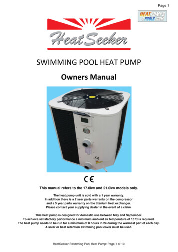
supplyairductingblowercondensatedrainThe first heat pumps to be massproduced were based on machines usedfor central air conditioning. The CarrierCorporation is widely recognized as oneof the first companies to commercialize residential centralcooling using vapor-compression refrigeration systems.During the 1950s, Carrier Corporation provided over 700early-generation central air-conditioning systems for oneof the first large-scale housing developments in Levittown,Pennsylvania.outsideinsidewarmair tobuildingcold airrefrigeranttubingreturnairductingfilterCrude heat pumps were developed inthe early 1900s but remained little morethan science experiments at a timewhen fossil fuels, especially coal andpetroleum, were the dominant energysource for heating buildings.Figure 1-1indoor air handlerto the thermodynamic underlying “heatengines,” which are devices that extractenergy from some higher-temperaturematerial and convert that energy intoa combination of mechanical workand lower-temperature heat. From athermodynamic perspective, a heatpump can be thought of as a heat engineoperating in reverse. It combines heatfrom a low-temperature source materialwith mechanical work to produce heatat a higher temperature. Carnot, buildingon the work of Kelvin, also developeda formula that sets the theoreticalperformance limits for any heat pump.refrigerant-to-airheat exchangercoolaircoolairair-to-air heat pumpoutdoor unitFigure 1-26Courtesy of Allied A/C & HeatingAlthough often taken for granted today, the advent ofcentral air conditioning at that time allowed scarcelypopulated areas in the southwestern U.S. to develop intomajor population centers. Some historians have even citedair conditioning as one of the most impactful technicalaccomplishments of the 20th century.Early-generation air-conditioning systems were only ableto cool buildings, absorbing heat from interior spaces anddissipating it to outside air. The next technological hurdlewas finding ways to reverse the direction of heat flow,and thus convert low-temperature heat in outside air intohigher-temperature heat to maintain comfort in buildings.This was the advent of air-to-air heat pumps.interior air handler using two copper refrigerant tubes. Thecompressor is located in the outdoor unit. The indoor unitcontains a refrigerant-to-air heat exchanger and blower.The basic configuration of a “split system” air-to-air heatpump, operating in heating mode, is shown in Figure 1-1.The outside unit, often called the “condenser” becauseof its origin in air-conditioning systems, connects to anAs is often the case with new technologies, earlyexperiences with air-to-air heat pumps were mixed. Firstgeneration products experienced higher than acceptablecompressor failure rates. In 1964, this reliability issue led
the U.S. Department of Defense to issue a ban on the useof heat pumps in military facilities due to the severity ofmaintenance problems. Fossil fuel continued to be thedominant energy source for heating buildings.The OPEC oil embargo, which began in 1973, reinvigoratedefforts to develop reliable electrically powered heat pumpsthat could lessen dependence on petroleum-basedheating fuels. Manufacturers of air-conditioning systemsworked on methods of reversing the direction of heat flow,and thus allow low-temperature heat in outside air to beraised to temperatures sufficient for heating buildings.One of the earliest attempts at creating a vaporcompression machine that could heat as well as coolsimply reversed the direction of the entire air conditionerwithin an opening in an exterior wall. Another used multipledampers to change airflow directions.Manufacturers eventually discovered that the refrigerantflows used in vapor-compression air conditioners couldbe reversed using a combination of four hand-operatedvalves. In time, this approach was replaced by two valvesoperated by electrical solenoids. Further development ledto a single 4-port, electrically operated “reversing valve.”This type of valve, which is discussed in more detail later inthis issue, is now used in a wide variety of heat pumps thatprovide heating and cooling.Figure 1-3Reversing valves made it practical to heat and cool homesusing air-to-air heat pumps. Sales of residential air-to-airheat pumps grew rapidly during the 1970s. The primarymarkets were southern states with relatively mild wintertemperatures and a definite need for summer cooling. Airto-air heat pumps became heavily promoted by southernelectric utilities, as well as by manufacturers such asCarrier, Westinghouse and General Electric.During the 1970s, the reliability of air-to-air heat pumpscontinually improved through revised compressor design,better lubrication details and techniques to reduce liquid“slugging” of compressors. By 1975, the U.S. Departmentof Defense lifted their previous ban on heat pumps in militaryfacilities. A surge of interest in heat pumps during 1976lead to an annual sales growth rate of 96%. Manufacturerswere having difficulty keeping up with demand. By 1978, itwas estimated that air-to-air heat pumps were installed inover 1.4 million U.S. homes.PERFORMANCE LIMITATIONSEarly generation air-to-air heat pumps could not operatewell at the low outdoor temperatures experienced inthe Northern U.S. and Canada. Many were limited tominimum outdoor temperatures in the range of 15-20ºF.If the outdoor temperature dropped below this limit, theheat pump would operate at grossly insufficient output orsimply turn off. The heating load would then be assumedby electric resistance “strip heaters,” which are heatingelements mounted in the supply air plenum on the heatpump’s interior unit, as shown in Figure 1-4.Courtesy of AD CooperStrip heat was usually activated by the second stage ofa 2-stage thermostat as room air temperature droppedslightly below the desired setting. Although reliable asa supplemental heat source, strip heat, like all electricresistance heating, is expensive to operate. Some earlygeneration air-to-air heat pumps were also installedalong with gas-fired furnaces that would assume the fullheating load if the heat pump could not operate due tolow outdoor temperature or some other condition.The inability to operate at the low outdoor air temperaturesexperienced in many northern states, and much ofCanada, created a stigma that air-source heat pumpswere only suitable for heating in mild climates. Thislimitation was one of the largest factors leading to theemergence of geothermal heat pumps during the 1980s.Because water returning from earth loops, wells or largeopen bodies of water was always above 32ºF, evenwhen outdoor air temperatures were extremely cold,geothermal heat pumps could provide predictable heatingperformance in northern climates. In milder climates,7
Figure 1-4blowerfilterindoor air handlercondensatedraingeothermal heat pumps also providedhigher-efficiency cooling performancecompared to early-generation airsource heat pumps. The NorthAmerican market for geothermal heatpumps has grown steady over thelast 30 years, largely driven by thepotential for high efficiency and thuslower operating cost.8cold refrigerant-to-airheat exchangerair-to-air heat pumpoutdoor unitFigure 1-5refrigeration pipingindoorevaporator &air handlerCOLD CLIMATE AIR-SOURCEHEAT PUMPSAs the market for geothermal heatpumps increased over the last 20years, so did efforts to improvethe performance of air-sourceheat pumps. New refrigerationtechnologies such as enhancedvapor injection (EVI), variablespeed “inverter” compressors, andelectronic expansion valves, noneof which were available for usein early-generation heat pumps,now allow modern air-source heatpumps to achieve significantly higherthermal performance at cold outdoortemperatures, in some cases as lowas -22ºF.insideelectricstrip heatauxiliaryheatingoutsidewarmair tobuildingair-cooledcondenserMany “cold climate” air-to-air heatpumps (a.k.a. “low ambient” airsource heat pumps) are currentlyavailable as “ductless” split systems.A single outdoor unit connects toone or more indoor air handlers usingrefrigeration piping. Figure 1-5 showsthe concept for a ductless split airto-air heat pump system with twointerior wall-mounted air handlers.
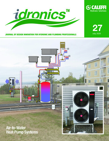
Figure 1-6MODERN AIR-TO-WATER HEAT PUMPSThe same innovations that now make ductless air-to-airheat pumps viable in cold climate applications have beenused to create air-to-water heat pumps. When operatingin heating mode, these units absorb heat from outdoorair, concentrate that heat to increase its temperature, andtransfer it to a stream of water or an antifreeze solution.The heated water can be used for a wide variety of loadssuch as hydronic space heating, domestic water heatingor pool heating. Air-to-water heat pumps can also bereversed to extract heat from an interior stream of waterand dissipate it to outside air. As such they can be usedto supply several types of chilled-water cooling distributionsystems. Modern air-to-water heat pumps provide anideal combination of low ambient thermal performancealong with the unsurpassed comfort and energy efficiencyafforded by modern hydronics technology.One example of a modern air-to-water heat pump is shownin Figure 1-8.The remainder of this issue will discuss the details forapplying modern air-to-water heat pumps in a variety ofheating and cooling applications.Figure 1-8Figure 1-7An example of a typical outdoor unit for a modern air-to-airheat pump is shown in Figure 1-6. One of the indoor airhandler units connected to this outdoor unit is shown inFigure 1-7.Although “ductless” split system heat pumps can providereasonably good thermal performance, they are limitedto space heating or cooling. They are also limited by thecompromises associated with forced air distribution.These include drafts, dispersal of dust and allergens,potential for clogged air filters, cool air collecting at floorlevel as warm air rises to ceiling level, possible aggravationof respiratory illnesses and objectionable interior noise.9
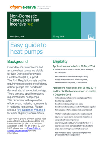
HEAT PUMP OPERATING FUNDAMENTALSFigure 2-2electricalpower input(Q2) Evaporator Compressor Condenser Thermal expansion valve (TXV)Q1To describe how this cycle works, aquantity of refrigerant will be followedthrough the complete cycle.Figure 2-1refrigerant flowcompressor2high temperaturehigh pressureVAPOR3condenserevaporator1Q2temperature source media into thelower-temperature refrigerant. Asthe refrigerant absorbs this heat,it changes from a liquid to a vapor(e.g., it evaporates). The vaporizedrefrigerant continues to absorb heatuntil it is slightly warmer than thetemperature at which it evaporates.The additional heat required to raisethe temperature of the refrigerantThe cycle begins at station (1)as cold liquid refrigerant withinthe evaporator. At this point, therefrigerant is colder than the sourcemedia (e.g., air or water) passingacross the evaporator. Becauseof this temperature difference,heat moves from the higher-SOURCEmediaSINKmedia4low temperaturelow pressureLIQUID10highertemperatureheatdissipatedto load(Q3)thermalexpansionvalve(TXV)The basic arrangement of thesecomponents to form a completerefrigeration circuit are shown inFigure 2-1.medium temperaturelow tabsorbedfrom source(Q1)condenserThe refrigeration cycle is the basis ofoperation of all vapor-compressionheat pumps. During this cycle, achemical compound called therefrigerant circulates around aclosed piping loop passing throughall major components of the heatpump. These major components arenamed based on how they affect therefrigerant passing through them.They are as follows:thermalexpansionvalve(TXV)medium temperaturehigh pressureLIQUIDQ3above its saturation temperature(e.g., where it vaporizes) is calledsuperheat, which also comes fromthe source media.This vaporized refrigerant then flows onto the compressor at station (2). Herea reciprocating piston or an orbitingscroll driven by an electric motorcompresses the vaporized refrigerant.This causes a large increase in bothpressure and temperature. Theelectrical energy used to operate thecompressor is also converted to heatand added to the refrigerant. Thetemperature of the refrigerant gasleaving the compressor is usually inthe range of 120º to 170ºF dependingon the operating conditions.The hot refrigerant gas then flows intothe condenser at station (3). Here ittransfers heat to a stream of water orair (e.g., the sink media) that carriesthe heat away to the load. As it givesup heat, the refrigerant changes froma high-pressure, high-temperaturevapor into a high-pressure, somewhatcooler liquid (e.g., it condenses).
The high-pressure liquid refrigerantthen flows through the thermalexpansion valve at station (4), where itspressure is greatly reduced. The drop inpressure causes a corresponding dropin temperature, restoring the refrigerantto the same condition it was in whenthe cycle began. The refrigerant isnow ready to repeat the cycle.The refrigeration cycle remains incontinuous operation whenever thecompressor is running. This cycle isnot unique to heat pumps. It is usedin refrigerators, freezers, room airconditioners, dehumidifiers, watercoolers, vending machines and otherheat-moving machines.Figure 2-2 shows the three primaryenergy flows involved in therefrigeration cycle. The first energyinput is low-temperature heatabsorbed from the source mediainto the refrigerant at the evaporator.The second energy input is electricalenergy flowing into the compressorwhenever it is operating. The thirdenergy flow is the heat output intothe sink media at the condenser.The first law of thermodynamicsdictates that, under steady stateconditions, the total energy input rateto the heat pump must equal the totalenergy output rate. Thus, the sum ofthe low-temperature heat absorptionrate into the refrigerant at theevaporator, plus the rate of electricalenergy input to the compr
What is a heat pump? History of heat pumps Performance limitations What is a heat pump? Cold climate air-source heat pumps 27 Performance limitations Modern air-to-water heat pumps 1. Government policy supporting 1. Government policy supporting 5. Lack of suitable combustion-based heat 2. Financial incentives: 3. Strong interest and impressive .