Transcription
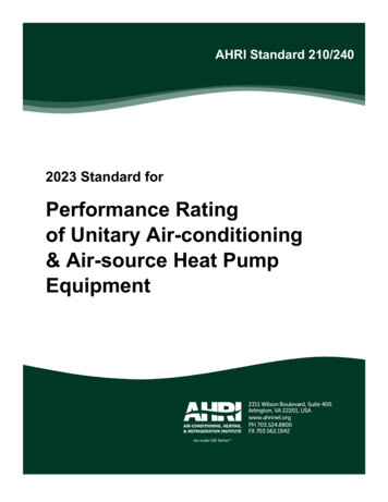
AHRI Standard 210/2402023 Standard forPerformance Ratingof Unitary Air-conditioning& Air-source Heat PumpEquipmentPrice 15.00 (M) 30.00 (NM)Printed in U.S.A. Copyright 2020, by Air-Conditioning, Heating, and Refrigeration InstituteRegistered United States Patent and Trademark Office
IMPORTANTSAFETY DISCLAIMERAHRI does not set safety standards and does not certify or guarantee the safety of anyproducts, components or systems designed, tested, rated, installed or operated in accordancewith this standard/guideline. It is strongly recommended that products be designed,constructed, assembled, installed and operated in accordance with nationally recognizedsafety standards and code requirements appropriate for products covered by thisstandard/guideline.AHRI uses its best efforts to develop standards/guidelines employing state-of-the-art andaccepted industry practices. AHRI does not certify or guarantee that any tests conducted underits standards/guidelines will be non-hazardous or free from risk.Note:This standard supersedes AHRI Standard 210/240-2017 with Addendum 1AHRI 210/240-2023, first published in May 2020, establishes a method to rate residential central air conditionersand heat pumps consistent with the test procedure codified in 10 CFR part 430, subpart B, appendix M1. The energyefficiency metrics, expressed in terms of Seasonal Energy Efficiency Ratio (SEER2), Energy Efficiency Ratio(EER2), and Heating Seasonal Performance Factor (HSPF2), are required for representations coincident with thecompliance date of the new efficiency standards in the United States starting on January 1, 2023.Price 15.00 (M) 30.00 (NM)Printed in U.S.A. Copyright 2020, by Air-Conditioning, Heating, and Refrigeration InstituteRegistered United States Patent and Trademark Office
FOREWORDThe primary changes in this edition of AHRI 210/240 are those required to align with the new performance metricsand requirements of Appendix M1 of 10 CFR 430, as issued by the U.S. Department of Energy (82 FR 1426, January2017). A working group of many stakeholders (including but not limited to AHRI members, independent laboratories,energy advocates and DOE consultants) met periodically over the course of two years to evaluate necessary changesand improvements in language.Because compliance with the Appendix M1 test procedure and ratings are not mandatory until January 1, 2023, AHRIhas chosen to use “2023” as the year version of this standard.Significant changes from AHRI 210/240-2017 with Addendum 1 include: Updates to comply with Appendix M1.o Added definitionso Change of performance metrics: EER to EER2 SEER to SEER2 HSPF to HSPF2 COP to COP2Removal of water-cooled and evaporatively-cooled products from the scope.o These products will be transitioned to 340/360.o Removal of sections on IEER/Part Load (only applicable to water-cooled andevaporatively-cooled products).Addition of requirements and calculations for the following:o Triple-capacity Northern Heat Pumpso Multiple Indoor BlowersUpdates to tables.Updates to calculations.Updated Appendix G with latest verbiage from 340/360.Price 15.00 (M) 30.00 (NM)Printed in U.S.A. Copyright 2020, by Air-Conditioning, Heating, and Refrigeration InstituteRegistered United States Patent and Trademark Office
AHRI CERTIFICATION PROGRAM PROVISIONSScope of the Certification ProgramThe Certification Program includes all Unitary Air-conditioning and Unitary Air-source Heat Pump equipment ratedbelow 65,000 Btu/h at AHRI Standard Rating Conditions (Cooling).Certified RatingsThe following Certification Program ratings are verified by test:Unitary Air-ConditionersAir-cooled AHRI Standard Rating Cooling Capacity, Btu/h Energy Efficiency Ratio (EER2A,Full), Btu/(W h) Seasonal Energy Efficiency Ratio (SEER2), Btu/(W h)Unitary Air-source Heat PumpsAir-cooled AHRI Standard Rating Cooling Capacity, Btu/h Energy Efficiency Ratio (EER2A,Full), Btu/(W h) Seasonal Energy Efficiency Ratio (SEER2), Btu/(W h) High Temperature Heating Standard Rating Capacity, Btu/h Region IV Heating Seasonal Performance Factor, HSPF2, Btu/(W h)Conformance to the requirements of the Maximum Operating Conditions Test, Voltage Tolerance Test, LowTemperature Operation Test (Cooling), Insulation Effectiveness Test (Cooling), and Condensate Disposal Test(Cooling), as outlined in Section 8, are also verified by test. Refer to the USAC/USHP Certification ProgramOperation Manual for more information regarding the AHRI Certification Program.Price 15.00 (M) 30.00 (NM)Printed in U.S.A. Copyright 2020, by Air-Conditioning, Heating, and Refrigeration InstituteRegistered United States Patent and Trademark Office
TABLE OF CONTENTSSECTIONPAGESection 1.Purpose. 1Section 2.Scope . 1Section 3.Definitions and Acronyms . 1Section 4.Classifications .11Section 5.Test Requirements .14Section 6.Rating Requirements . 18Section 7.Minimum Data Requirements for Published Ratings .37Section 8.Operating Requirements . 37Section 9.Marking and Nameplate Data .40Section 10. Conformance Conditions . 40Section 11. Calculations.40Section 12. Symbols, Subscripts and Superscripts .75TABLESTable 1.Classification of Unitary Air-conditioners.12Table 2.Classification of Unitary Air-source Heat Pumps . 13Table 3.Classification of Multi-split Systems . 14Table 4.Refrigerant Line Length Correction Factors . 16Table 5.Test Condition Tolerance for Charging Hierarchy . 17Table 6.Informative Guidance for Using AHRI Standard 210/240 . 19Table 7.Required Tests . 20Table 8.Test Conditions for Air-cooled Products . 21
TABLES (Cont’d)Table 9.Values of Standard Capacity Ratings. 22Table 10.Minimum ESP for Ducted Systems Tested with an Indoor AMSInstalled . 26Table 11.Application Rating Conditions for I-P Standards . 33Table 12.t Statistic . 34Table 13.Fractional Bin Hours to Be Used in Calculation of SEER2 . 48Table 14.Distribution of Fractional Heating Hours in Temperature Bins, Heating Load Hours,and Outdoor Design Temperature for Different Climatic Regions. 55FIGURESFigure 1.Voltage Tolerance Test Power Interrupt Procedure.38Figure 2.Schematic of a Single-speed System Operation in the Cooling Mode .47Figure 3.Cooling Load Hours (CLHA) for the United States .48Figure 4.Schematic of a Two-speed System Operation in the Cooling Mode .49Figure 5.Schematic of a Variable Speed System Operation in the Cooling Mode .52Figure 6.Heating Load Hours (HLHA) for the United States .56Figure 7.Schematic of a Single-speed Heat Pump Operation in Heating Mode .61Figure 8.Schematic of a Two-speed Heat Pump Operation in Heating Mode .62Figure 9.Schematic of a Variable Speed Heat Pump Operation in Heating Mode . 66APPENDICESAppendix A.References – Normative . 81Appendix B.References – Informative .83Appendix C.Certification of Laboratory Facilities Used to Determine Performance ofUnitary Air-conditioning & Air-source Heat Pump Equipment –Informative .84Appendix D.Secondary Capacity Check Requirements - Normative . 101
Appendix E.ANSI/ASHRAE Standard 37-2009 Clarifications/Exceptions– Normative .108Appendix F.ANSI/ASHRAE Standard 116-2010 Clarifications/Exceptions– Normative .118Appendix G.Unit Configuration for Standard Efficiency Determination - Normative .125Appendix H.Off-mode Testing - Normative .130Appendix I.Verification Testing - Normative .134FIGURES FOR APPENDICESFigure C1.Passive Pressure Drop Device .95Figure E1.Configurations for Manifolding the Static Pressure Taps. 111Figure E2.Typical Air Sampling Tree .114Figure E3.Aspirating Psychrometer . 115TABLES FOR APPENDICESTable C1.Nozzle Combination Tests .88Table C2.Nominal Dimensions for Passive Pressure Drop Device .94Table E1.Pressure Measurement Location .113Table G1.Test Procedures and Reference Motor Efficiency .128Table G2.BLDC Motor and ECM – Fractional hp – Reference Efficiencies . 129Table I1.Acceptance Criteria . 134
AHRI STANDARD 210/240-2023PERFORMANCE RATING OF UNITARY AIRCONDITIONING AND AIR-SOURCE HEATPUMP EQUIPMENTSection 1. Purpose1.1 Purpose. The purpose of this standard is to establish the following for Unitary Air-conditioners and Unitary Air-sourceHeat Pumps: definitions, classifications, test requirements, rating requirements, operating requirements, minimum datarequirements for Published Ratings, marking and nameplate data, and conformance conditions.1.1.1Intent. This standard is intended for the guidance of the industry, including manufacturers, engineers, installers,contractors and users.1.1.2Review and Amendment. This standard is subject to review and amendment as technology advances.Section 2. Scope2.1 Scope. This standard applies to factory-made Unitary Air-conditioners and Unitary Air-source Heat Pumps withcapacities less than 65,000 Btu/h as defined in Section 3.2.1.12.2Energy Source. This standard applies only to electrically operated, vapor compression refrigeration systems.Exclusions. This standard does not apply to the rating and testing of:2.2.1Heat operated air-conditioning/heat pump equipment.2.2.2Packaged Terminal Air-conditioners/Heat Pumps, as defined in AHRI Standard 310/380.CSA C744.2.2.3Room air-conditioners/heat pumps.2.2.4Unitary Air-conditioners and Unitary Air-source Heat Pumps as defined in AHRI Standard 340/360 withcapacities of 65,000 Btu/h or greater.2.2.5Water-source Heat Pumps, Ground Water-source Heat Pumps, or ground-source closed-loop Heat Pumps asdefined in ISO/ANSI/ASHRAE/AHRI Standards 13256-1 and 13256-2.2.2.6Water heating heat pumps.2.2.7Units equipped with desuperheater/water heating devices in operation.2.2.8Variable Refrigerant Flow Air Conditioners and Heat Pumps as defined in AHRI Standard 1230 with capacitiesof 65,000 Btu/h and greater.2.2.9Single Packaged Vertical Units as defined in ANSI/AHRI Standard 390.Section 3. Definitions and AcronymsAll terms in this document will follow the standard industry definitions in the ASHRAE Terminology ions/free-resources/ashrae-terminology) unless otherwise defined in this section.Further definitions are found in Appendices C, D and E. For reference purposes, the user of this standard is informed there arealso pertinent definitions in Title 10, Code of Federal Regulations, Part 430, Subpart 430.2. Throughout the standard definedterms are capitalized.3.1Definitions.1
AHRI STANDARD 210/240-20233.1.1Air-cooled Air-conditioner. An air-conditioner which uses air as the medium to absorb heat in order tocondense refrigerant.3.1.2Airflow-control Setting(s). Programmed or wired control system configurations that control a fan to achievediscrete, differing ranges of airflow—often designated for performing a specific function (e.g., cooling, heating, orconstant circulation)—without manual adjustment other than interaction with a user-operable control (i.e., a thermostat)that meets the manufacturer specifications for installed-use. For the purposes of this standard, manufacturerspecifications for installed-use are those found in the product literature shipped with the unit.3.1.3Airflow Prevention Device. A device that prevents airflow via natural convection by mechanical means, suchas an air damper box, or by means of changes in duct height, such as an upturned duct.3.1.4Air Moving System (AMS).3.1.4.1 Constant-volume AMS. A fan system that varies its operating speed to provide a fixed air-volume-ratefrom a Ducted System.3.1.4.2 Constant-torque AMS. A fan system that maintains constant motor shaft torque over a broad range ofloads.3.1.4.3 Permanent Split Capacitor (PSC) AMS. A fan system connected to an induction motor that developsmotor shaft torque proportional to the RPM slip from synchronous speed.3.1.5Approach Temperature. The refrigerant temperature at the outdoor liquid service port minus the outdoorambient temperature.3.1.63.1.7Blower Coil System. A Split System that includes one or more Blower Coil Indoor Units.Ceiling-mount Blower Coil System. A ducted split system for which all of the following apply:3.1.7.1 The Outdoor Unit has a certified cooling capacity less than or equal to 36,000 Btu/h.3.1.7.2 The Indoor Unit(s) is/are shipped with manufacturer-supplied installation instructions that stipulate tosecure the indoor unit only to the ceiling, within a furred-down space, or above a dropped ceiling of theconditioned space, with return air directly to the bottom of the unit without ductwork, or through the furreddown space, or optional insulated return air plenum that is shipped with the indoor unit.3.1.7.3 The installed height of the Indoor Unit is no more than 12 inches (not including condensate drain lines)and the installed depth (in the direction of airflow) of the indoor unit is no more than 30 inches.3.1.7.4 Supply air is discharged horizontally.3.1.8Coefficient of Performance (COP2). A ratio of the cooling/heating capacity in watts to the power input valuesin watts at any given set of Rating Conditions expressed in watt/watt (a dimensionless quantity). For heating COP2,supplementary resistance heat shall be excluded.3.1.9Coil-only System (Coil-only Air-conditioner or Coil-only Heat Pump). A system that includes only (one ormore) Coil-only Indoor Units.3.1.10 Crankcase Heater. Any electrically powered device or mechanism for intentionally generating heat withinand/or around the compressor sump volume. Crankcase Heater control may be achieved using a timer or may be basedon a change in temperature or some other measurable parameter, such that the Crankcase Heater is not required to operatecontinuously. A Crankcase Heater without controls operates continuously when the compressor is not operating.3.1.11 Cyclic Test. A test where the unit's compressor is cycled on and off for specific time intervals. A Cyclic Testprovides half the information needed to calculate a Degradation Coefficient.3.1.12Defrost Control System.3.1.12.1 Demand-defrost Control System. A system that defrosts the heat pump Outdoor Coil only whenmeasuring a predetermined degradation of performance. The heat pump's controls shall do one of the following:2
AHRI STANDARD 210/240-20233.1.12.1.1 Monitor one or more parameters that always vary with the amount of frost accumulated onthe Outdoor Coil (e.g., coil to air differential temperature, coil differential air pressure, outdoor fan power orcurrent, optical sensors, etc.) at least once for every ten minutes of compressor ON-time when space heating.3.1.12.1.2 Operate as a feedback system that measures the length of the defrost period and adjustsdefrost frequency accordingly. In all cases, when the frost parameter(s) reaches a predetermined value, thesystem initiates a defrost. In a Demand-defrost Control System, defrosts are terminated based on monitoring aparameter(s) that indicates that frost has been eliminated from the coil. A Demand-defrost Control System,which otherwise meets the above requirements, shall allow time-initiated defrosts if, and only if, such defrostsoccur after 6 hours of compressor operating time.Note: Systems that vary defrost intervals according to outdoor dry-bulb temperature are not demand defrostsystems.3.1.12.2 Time Adaptive Defrost Control System. A Demand-defrost Control System that measures the lengthof the prior defrost period(s) and uses that information to automatically determine when to initiate the nextdefrost cycle.3.1.12.3 Time-temperature Defrost Control System. A control system that initiates or evaluates initiating adefrost cycle only when a predetermined cumulative compressor ON-time is obtained. This predeterminedON-time is generally a fixed value (e.g., 30, 45, 90 minutes) although it may vary based on the measuredoutdoor dry-bulb temperature. The ON-time counter accumulates if controller measurements (e.g., outdoortemperature, evaporator temperature) indicate that frost formation conditions are present, and it is reset/remainsat zero at all other times. In one application of the control scheme, a defrost is initiated whenever the countertime equals the predetermined ON-time. The counter is reset when the defrost cycle is completed.In a second application of the control scheme, one or more parameters are measured (e.g., air and/or refrigeranttemperatures) at the predetermined, cumulative, compressor ON-time. A defrost is initiated only if themeasured parameter(s) falls within a predetermined range. The ON-time counter is reset regardless of whethera defrost is initiated. If systems of this second type use cumulative ON-time intervals of 10 minutes or less,then the heat pump may qualify as having a Demand-defrost Control System.3.1.13 Degradation Coefficient (CD). A parameter used in calculating the Part Load Factor, which is a measure of theefficiency loss due to the cycling of the units. The Degradation Coefficient for cooling is denoted by 𝐶𝐷𝑐 . TheDegradation Coefficient for heating is denoted by 𝐶𝐷ℎ .3.1.14 Double-duct System. Double-duct Air-conditioner or Heat Pump means air-cooled commercial package airconditioning and heating equipment that is either a) a horizontal Single Package Unit or Split System, or b) a verticalunit that consists of two components that shall be shipped or installed either connected or split; and is intended for indoorinstallation with ducting of outdoor air from the building exterior to and from the unit, where the unit and/or all of itscomponents are non-weatherized and are not marked (or listed) as being in compliance with UL 1995/CSA C22.2 No.236or equivalent requirements for outdoor use. If it is a horizontal unit, the complete unit shall have a maximum height of 35 in or the unit shall havecomponents that do not exceed a maximum height of 35 in. If it is a vertical unit, the complete (split, connected, or assembled) unit shall have components that do notexceed maximum depth of 35 in; and, a rated cooling capacity less than 65,000 Btu/h.3.1.15 Ducted System. An air-conditioner or heat pump that is designed to be permanently installed and deliversconditioned air to the indoor space through a duct(s). The air-conditioner or heat pump may be either a Split Systemunit or a Single Package Unit.3.1.16 Energy Efficiency Ratio (EER2). A ratio of the cooling capacity in Btu/h to the Total Power in watts at anygiven set of Rating Conditions expressed in Btu/(W h).3.1.16.1 EER2A,Full. The EER2 at AFull test conditions.3.1.17 Gross Capacity. The calculated system capacity that results when not accounting for the heat generated froman indoor supply fan.3
AHRI STANDARD 210/240-20233.1.18 Heat Comfort Controller. A heat pump control that regulates the operation of the electric resistance elementsto assure that the air temperature leaving the indoor section does not fall below a Specified temperature even if the heatpump capacity exceeds the building load. This Specified temperature is usually field adjustable and the temperatureshall be Specified by the manufacturer as part of the equipment rating. Heat pumps that actively regulate the rate ofelectric resistance heating when operating below the balance point (as the result of a second stage call from thethermostat) but do not operate to maintain a minimum delivery temperature are not considered as having a heatcontroller.3.1.19April.Heating Season. The months of the year that require heating, e.g., typically, and roughly, October through3.1.20 Heating Seasonal Performance Factor (HSPF2). The total space heating required during the space heatingseason, Btu, divided by the total electrical energy, W h, consumed by the heat pump system during the same season,Btu/(W h). HSPF2 will vary depending on the region (refer to Section 11).3.1.21 Independent Coil Manufacturer (ICM). A company that manufactures Indoor Units but does not manufactureSingle Package Units or Outdoor Units.3.1.22 Indoor Unit. A separate assembly of a Split System that includes both an arrangement of refrigerant-to-air heattransfer coil(s) for transfer of heat between the refrigerant and the indoor air and a condensate drain pan. An IndoorUnit may or may not include sheet metal or plastic parts not part of external cabinetry to direct/route airflow over thecoil(s), a cooling mode expansion device, external cabinetry, and an integrated indoor blower (i.e. a device to move airincluding its associated motor). A separate designated air mover that may be a furnace or a Modular Blower may beconsidered to be part of the Indoor Unit. A Service Coil is not an Indoor Unit.3.1.22.1 Blower Coil Indoor Unit. An Indoor Unit with either a) an indoor blower housed with the coil or b) aseparate designated air mover such as a furnace or Modular Blower.3.1.22.2 Air Handler. An arrangement of refrigerant-to-air heat transfer coil(s), condensate drain pan, sheetmetal or plastic parts to direct/route airflow over the coil(s), air moving device, and external cabinetry. An AirHandler may or may not include a cooling mode expansion device and/or supplemental resistive heatingelements.3.1.22.3 Modular Blower. A product which only uses single-phase electric current, and which meets all of thefollowing:3.1.22.3.1 Is designed to be the principal air circulation source for the living space of a residence.3.1.22.3.2 Is not contained within the same cabinet as a furnace or central air-conditioner.3.1.22.3.3 Is designed to be paired with HVAC products that have a heat input rate of less than225,000 Btu per hour and cooling capacity less than 65,000 Btu per hour.3.1.22.4 Coil-only Indoor Unit. An Indoor Unit that is distributed in commerce without an indoor blower orseparate designated air mover. A Coil-only Indoor Unit installed in the field relies on a separately-installedfurnace or a Modular Blower for indoor air movement.3.1.22.4.1 Cased Coil. A Coil-only Indoor Unit with external cabinetry.3.1.22.4.2 Uncased Coil. A Coil-only Indoor Unit without external cabinetry.3.1.22.5 Service Coil. An arrangement of refrigerant-to-air heat transfer coil(s), condensate drain pan, sheetmetal or plastic parts to direct/route airflow over the coil(s), sold specifically for the intent of replacing anUncased Coil or Cased Coil that has already been placed into service, and that has been labeled “for indoor coilreplacement only” on the nameplate and in manufacturer technical and product literature. The model numberfor any Service Coil shall include some mechanism (e.g., an additional letter or number) for differentiating aService Coil from a coil intended for an Indoor Unit. A Service Coil may or may not include external cabinetryand/or a cooling mode expansion device.3.1.23 Installation Instructions. Manufacturer’s documentation that come packaged with or appear in the labelsapplied to the unit. This does not include online manual.4
AHRI STANDARD 210/240-20233.1.24 Latent Cooling Capacity. The rate, expressed in Btu/h, at which the equipment removes latent heat (reducesthe moisture content) of the air passing through it under standard conditions of operation.3.1.25 Low-static Blower Coil System. A ducted multi-split or multi-head mini-split system for which all indoor unitsproduce greater than 0.01 in H2O and a maximum of 0.35 in H2O ESP when operated at the cooling full-load air volumerate not exceeding 400 cfm per rated ton of cooling.3.1.26 Mid-static Blower Coil System. A ducted multi-split or multi-head mini-split system for which all indoor unitsproduce greater than 0.20 in H2O and a maximum of 0.65 in H2O ESP when operated at the cooling full-load air volumerate not exceeding 400 cfm per rated ton of cooling.3.1.27 Minimum-speed-limiting Variable-speed Heat Pump. A heat pump for which the minimum compressor speed(represented by revolutions per minute or motor power input frequency) is higher than its minimum value for operationin a 47 F ambient temperature for any bin temperature tj for which the calculated heating load is less than the calculatedintermediate-speed capacity.3.1.28 Mobile Home Blower Coil System. A split system that contains an outdoor unit and an indoor unit that meet thefollowing criteria:3.1.28.1 Both the indoor and outdoor unit are shipped with manufacturer-supplied installation instructions thatstipulate installation only in a mobile home with the home and equipment complying with HUD ManufacturedHome Construction Safety Standard 24 CFR part 3280;3.1.28.2 The indoor unit cannot exceed 0.40 in H2O when operated at the cooling full-load air volume rate notexceeding 400 cfm per rated ton of cooling; and3.1.28.3 The indoor and outdoor unit each must bear a label in at least 1 4 in font that reads “For installationonly in HUD manufactured home per Construction Safety Standard 24 CFR part 3280.”3.1.29 Mobile Home Coil-only System. A coil-only split system that includes an outdoor unit and coil-only indoor unitthat meet the following criteria:3.1.29.1 The outdoor unit is shipped with manufacturer-supplied installation instructions that stipulateinstallation only for mobile homes that comply with HUD Manufactured Home Construction Safety Standard24 CFR part 3280;3.1.29.2 The coil-only indoor unit is shipped with manufacturer-supplied installation instructions that stipulateinstallation only in or with a mobile home furnace, modular blower, or designated air mover that complies withHUD Manufactured Home Construction Safety Standard 24 CFR part 3280, and has dimensions no greater than20 in wide, 34 in high and 21 in deep; and3.1.29.3 The coil-only indoor unit and outdoor unit each has a label in at least 1 4 in font that reads ‘Forinstallation only in HUD manufactured home per Construction Safety Standard 24 CFR part 3280.”3.1.30 Multiple-circuit (or Multi-circuit) System. A Split System that has one Outdoor Unit and that has two or moreIndoor Units installed on two or more refrigeration circuits such that each refrigeration circuit serves a compressor andone and only one Indoor Unit, and refrigerant is not shared from circuit to circuit.3.1.31 Multiple Capacity (Multiple Stage) Compressor. A compressor having three or more stages of capacity thathas neither an inverter, nor variable frequency drive, or a group of compressors with three or more stages of capacity.3.1.31.1 Full Compressor Stage (Full). The staging of compressor(s) as Specified by the manufacturer at whichthe unit operates at full load test conditions. The Full Compressor Stage for heating mode tests may be thesame or different from the cooling mode value.3.1.31.2 Intermediate Compressor Stage (Int).3.1.31.2.1 For Multi-split Systems. The staging of compressor(s) as Specified by the manufacturerthat falls within one-fourth and three-fourths of the difference between the Low C
2.2.1 Heat operated air-conditioning/heat pump equipment. 2.2.2 Packaged Terminal Air-conditioners/Heat Pumps, as defined in AHRI Standard 310/380.CSA C744. 2.2.3 Room air-conditioners/heat pumps. 2.2.4 Unitary Air-conditioners and Unitary Air-source Heat Pumps as defined in AHRI Standard 340/360 with capacities of 65,000 Btu/h or greater.

