Transcription
PYOCLNAOISIVPROGrant ASHE Air Source Heat PumpAir to Water High Efficiency Heat Pump RangeInstallation & User InstructionsTested to BS EN 14511Part No. DOC.93 Rev.00 April 2013
STOP!Before continuing with the installation of your new Aerona Heat pump, please spenda few minutes confirming the suitability of the Heat Pump to your system. Failure todo so may result in poor performance and wasted time. Has a heat loss calculation been carried out?kW Is this system designed for Mono or Bivalent If Mono, total heating capacity?kW If Bivalent, what is the load capacity of Heat Pump?kW If Bivalent, what is/are additional heat source(s)?i)kWii)kWiii)kW Type of system design?i)S-planii)Y-planiii) Other Will a buffer be used?STOP If yes, what is the capacity of Buffer?2Yes/Nolitres Has cavity wall insulation been installed?Yes/No Has loft insulation of 270mm been installed?Yes/No Have all system pipes been lagged correctly?Yes/No Are the existing controls being upgraded?Yes/NoIf any of the above questions cannot be answered accurately, please do NOTproceed with the installation. While any errors made now may be able to becompensated for after the installation is completed, you will incur unnecessarydelays and additional costs.
Contents22Contents3Legislation31319.2 Heat Pump Cylinders3149.3 Temperature Boost31Introduction510 Filling the System331.1 General Information510.1 Filling and Venting - Sealed Systems331.2 Warranty510.2 Flushing and Corrosion Protection331.3 Important Advice51.4 Immersion Heater511 Commissioning3411.1 Switching on First Time34611.2 Setting the ATC Controller352.1 Specifications611.3 Additional Operating Information2.2 Dimensions6Specifications and Controlsabout the ATC382.3 Heat Pump Operating Sequences811.4 Setting the BTC Controller2.4 Controls811.5 Checking the BTC Controller39911.6 Setting the BTC Controller401011.7 ATC Commissioning Data4111.8 Record of BTC Settings4312 Servicing & Maintenance442.6 Performance GraphsSiting the Heat Pump3.1 Position3.2 Orientation4Domestic Hot Water9.1 Temperature Control2.5 Pump Curves39Hydraulic Diagrams1111121312.1 General394412.2 Air Inlet and Outlet4412.3 Condensate Disposal444.1 S-Plan Type - Monovalent1312.4 Heating System Connections444.2 Extended S-Plan Type - Monovalent1312.5 Heat Pump Controls444.3 S-Plan Type - Bivalent1412.6 Refrigerant444.4 Extended S-Plan Type - Bivalent154.5 Buffer Tanks164.6 S-Plan with Buffer - Monovalent164.7 Extended S-Plan with Buffer - Monovalent 175System Design Criteria186Calculating Radiator Sizes197Sealed Systems208Electrical218.1 General218.2 Basic Circuits – Making the Connection218.3 Controller228.4 Mains Supply Cable238.5 Heat Pump Wiring Diagrams248.6 System Control Wiring Diagrams288.7 Wiring Diagrams2913 Fault Finding4513.1 If Heat Pump Fails to Start4513.2 Heating System Controls4513.3 Warm Weather Shut Down (WWSD)4513.4 Operation of MCB/RCD's4513.5 Temperature Sensors4513.6 Refrigerant Pressure Gauge4513.7 Power Capacitors4514 Accessories4815.1 Sealed System Kits4815.2 Immersion Heater Kits4815 Spare Parts4916 Glossary Of Terms5017 Warranty518.8 Bivalent Systems2917.1 Warranty8.9 Solar Thermal2917.2 Extended Warranty8.10 Buffer Tanks298.11 Bivalent Electrical Diagram305152Contents1Stop!3
LegislationAll work that is required regarding the refrigerant circuit must be carried out by anF-gas registered (or equivalent) refrigeration Engineer. On no account shouldmaintenance or repair be carried out on the refrigerant circuit by unqualified personnel.Information regarding the refrigerant used in this Heat Pump. R407cR407C is a mixture of three refrigerants, each of which boil at different temperatures. R407C has a range or glide of approximately5ºC. The lubricating oils used in this heat pump are known as Polyolester or POE oils. They are considered to be superior oils, lessliable to breakdown however they are more hygroscopic – they must therefore be kept from contact with air as far as is practical.Information regarding the charging / recharging of the unit.Always add R407C as a liquid to ensure that the correct mix is added.Charge the heat pump with the correct weight of refrigerant. See data plate for this information.Never ‘top-up’ refrigerant. Always recover the remaining refrigerant first for recycling.Information regarding a refrigerant leak or if the circuit is opened accidentally.Recover the remaining refrigerant as quickly as possible for recycling.Avoid entry of air into the heat pump as much as possible.Replace or install a drier if necessary.LEGISLATIONThe installation of the Grant Aerona Heat Pump requires a power supply cable fromthe customer’s consumer unit to an external isolation switch and from this switch tothe heat pump. It will require a final connection to an individual MCB or RHBO withinthe existing consumer unit or from a newly installed consumer unit.This work MUST be carried out by a qualified electrician or by a Part-P competentinstaller who has passed an examination proving their competency in these works.Failure to follow this legislation will invalidate all warranties.Please seek advice from a competent person before commencing any electrical work.CE MarkingLegislationThe Grant Aerona range of Air Source Heat Pumps are CE marked and conform to the requirements of the followingDirectives and Standards:Low VoltageElectromagnetic Compatibility (EMC)Pressure Equipment Directive (PED)Electrical Equipment73/23 EEC, modified 93/68 EEC.89/336 EEC, modified 92/3197/23/ECEN 60 335-2The following Standards and Directives should also be considered in the installation and application of the heat pumps:BS7671: 2008 IEE Wiring Regulations - 17th edition (including and any amendments)BS EN 15450: 2007 Heating systems in buildings – Design of Heating SystemsEC Regulation No. 842/2006HVAC TR/30 Guide to good practice - Heat pumps4
1 Introduction & General InformationThe Grant Aerona Heat Pump is a lowwater content – low temperature heatsource, designed to be highly efficientwhen installed and used in line withthese installation and user instructions.It is important that these installationinstructions are understood andfollowed to ensure reliable operation inall weather conditions. Failure to do sowill result in erratic temperature swings,poor efficiency and an unhappycustomer.It is not within the scope of this manualto design the heating system or provideany advice regarding the layout of thesystem or any of the controls requiredfor any individual heating system.These instructions do not replace theinstallation or users manuals for anyadditional components used in thedesign of your system e.g. cylinders,motorised valves, programmers, solarthermal devices, buffers, etc.Grant Engineering UK Ltd offer a designservice for an additional fee – pleasecontact info@grantuk.com for moreinformation or visit our website atwww.grantuk.com Note: this serviceis subject to the terms and conditions inforce at the time of the design.These instructions must be left with thehouseholder for their reference.1.2 WarrantyThis appliance is guaranteed for twoyears, covering parts and labour. Whenmaking a claim against this warranty,the following information must beprovided at the initial point of contact. Appliance model number Appliance Serial number Date of Installation Date of Commissioning (if different) Description of fault together with anyrelevant fault codesPlease ensure that the caller ison site to assist us in providinga fast response.The warranty will begin only when acompleted registration card is returnedto Grant, or when the registration iscompleted online at www.grantuk.com.Failure to complete the registration atthe time of installation will result in thewarranty being suspended. This doesnot affect the consumer’s statutoryrights.If a Grant Engineer is required to visitthe site and no fault is found with theheat pump, a charge will be made forthis visit. The original caller will beresponsible for this charge.Refer to Section 17 for full details of theGrant Heat Pump warranty.1.3 Important Advice1. It is essential that the full layout ofthe system is understood before theinstallation of any component isundertaken. If you are in any doubt,please stop and seek advice from aqualified heating engineer or fromGrant Engineering UK Ltd. Pleasenote that Grant Engineering will notbe able to offer specific adviceabout your system unless wedesigned it. In this case, we willalways refer you to seek the adviceof a qualified system designer.2. The Heat Pump must be installedand commissioned in accordancewith these installation instructions.Deviations of any kind will invalidatethe warranty and may cause anunsafe situation to occur. Pleaseseek advice from Grant EngineeringUK Ltd if any of these installationinstructions cannot be followed forwhatever reason. Evidence of Heat Loss calculationIMPORTANTGrant Aerona heat pumps should be stored andtransported in an upright position. If not, the heatpump MUST be positioned in an upright position forat least 4 hours before being operated.3. The heat pump contains highpressures and high temperaturesduring normal working conditions.Care must be taken whenaccessing the internal workings ofthe heat pump.4. The heat pump contains anelectrically driven fan which rotatesat high speed. Disconnect the heatpump from the electrical supplybefore removing the top cover.1.4 Immersion HeaterAll Grant Aerona Heat pumps aresupplied with a factory fitted 3kWimmersion element. This is designed tooperate at low ambient air temperaturesto increase the output of the unit tomeet the design heat load. Refer toSection 11 of these instructions fordetails of the automatic operation of theimmersion element.If required, all Grant Aerona Heatpumps are available with a 6kW backup immersion element (in place of thestandard 3kW unit).This is a factory fitted option ONLY andmust be specified when ordering theheat pump.For the starting and running current,along with the required MCB rating/typefor units with either the 3kW or 6kWimmersion elements refer to Section 8(page 19) of these instructions.Introduction &General Information1.1 General Information5
2 Specifications and Controls2.1 SpecificationsModelHeating 1.20A2224283640Power leFrequencyHzMechanical ProtectionRefrigerantMass of R410a5050505050IP X4IP X4IP X4IP X4IP X4R410AR410AR410AR410AR410A2 x 2800g2000220024002 x 2000Built In ImmersionkW33333Circulating Pumpm head6681515Flow Rate1.020litres/sec0.3280.4160.5790.840Sound Power Level at 1m**dB(A)62.562.56468.563Sound Pressure Level at 1mdB(A)47.748495348.5Water OP @ Air 7 C/Water 35 CWeight (empty)kg116145173233334Weight (full)kg119148176237339* Includes 3kW immersion heater.** To EN14511.2.2 DimensionsSpecifications andControlsASHE85Max. Running Current at 230V*Phase6ASHE65Figure 2-1: ASHE65 Dimensions
2.2 Dimensions continuedFigure 2-2: ASHE85 & ASHE125 DimensionsSpecifications andControlsFigure 2-3: ASHE175 DimensionsFigure 2-4: ASHE215 Dimensions7
2 Specifications and Controls2.3 Heat Pump Operating SequencesASHE65, ASHE85 and ASHE125PumpPumpFanFanCompressorCompressor4-way Valve4-way ValveHeatDemandDefrostDemandTime (secs)Time (secs)on15offFigure 2-5: Normal operating sequenceon25 30off25 30off10 25 30Figure 2-6: Defrost cycleASHE175 and ASHE215PumpPumpFanFanCompressor 1Compressor 1Compressor 2Compressor 24-way Valve4-way ValveHeatDemandDefrostDemandTime (secs)on15 20Figure 2-7: Normal operating sequenceoffTime (secs)on25 35 40Figure 2-8: Defrost cycle2.4 ControlsSpecifications andControlsAll Grant Aerona Heat Pumps aresupplied with 2 controllers. 1 x heatpump controller (ATC) and 1 xtemperature controller (BTC).8The ATC is positioned inside thehouse/building and is normally used inan automatic condition. There are a fewparameters that can be adjustedincluding time and maximum watertemperature. The details of thesesettings can be found in Section 11 ofthis manual.The BTC is a split temperaturecontroller located inside the heat pump.For many installations, the HWtemperature and the CH temperaturewill be different. The BTC allows for 2different design temperatures to beentered, maximising the efficiency of theGrant Aerona heat pump. The details ofthese settings can be found in Section11 of this manual.All other controls (programmers,motorised valves, thermostats, etc) arenot supplied but their use is covered inSections 4 and 8 of this installationmanual.Figure 2-9: ATC ControllerFigure 2-10: BTC Controller
2.5 Pump ump Head (metres)61(Min)00123Q (m3/h)456Figure 2-11: Pump curves for ASHE65, ASHE85 (RS-15/6) and ASHE125 (RS-25/8)20181412H (metres)PUN-200E1086400102030405060Flow (m3/h)Figure 2-12: Pump curve for ASHE175 and ASHE215708090100Specifications andControls29
2 Specifications and Controls2.6 Performance GraphsASHE65ASHE175730712625610563Output in -12-1573571463065255Output in 2525!762015431025100151272-3-7-12-15COPOutput in kW5NOTEAll Grant ASHE Heat Pumps havebeen independently third partytested to BS EN 14511: 2007.The COP data given above is basedon 7 C ambient air and 35 C watertemperature. This information shouldbe used as guidance only andshould not be used to estimate theCOP at other temperatures.-7-12-15COP208COP4Output in kW1610Specifications andControls-7ASHE2151210COP8520COPOutput in kW14
3 Siting the Heat Pump3.1 Position1. BaseThe heat pump should be installedon a flat trowelled finished concretebase 150mm thick. This baseshould extend at least 100mmbeyond the unit on three sides. Theedge of the concrete base on theside closest to the building shouldbe flush with that face of the heatpump. Refer to Figure 3-1.300mmminimumDeflectorplate (not onASHE125)To avoid bridging the DPC, leave agap of at least 300mm between theconcrete base and the wall of thehouse.Edge of baseflush with rearof heat pumpDPC200mm min aboveground levelConcrete base150mmminimumTrench with chippingsFigure 3-1: Installation detailsIMPORTANTIt is essential that the condensate is able to drainaway and not allowed to run onto any adjacentpaths or driveways where, in winter, this will resultin icing and a potential hazard for anyone walkingnear the heat pump.The top of the concrete base must be either level with,or above, the surrounding ground level. Always ensureat least 200mm vertical clearance between thesurrounding ground level and the underside of theheat pump to allow for adequate air movement. Referto Figure 3-1 for details.2. ClearancesThe Heat pump should have aminimum of 300mm from the rearof the unit to any wall and not haveany obstruction within 1000mmfrom the front or either side of theunit. Do not rest objects on top oragainst any part of the heat pumpunder any circumstances. Do notinsert objects into the fan guard.3. Noise LevelAll heat pumps make a noise.Discuss the potential nuisancefactor with the end-user whenconsidering the final position of theheat pump. Take opening windowsand doors into account. It is notessential for the heat pump to bepositioned next to a wall of thehouse. Behind an out-building maybe more suitable so discuss theoptions with the end-user.4. InsulationRemember, all pipe work,irrespective of length, must be wellinsulated to prevent heat loss. Theuse of barrier plastic pipe togetherwith double thick insulation isstrongly recommended, particularlywhen considering longer pipe runs.Siting the Heat PumpThe Underside of the heat pump isfitted with a condensate deflectorthat directs the condensate to therear of the unit. To allow thiscondensate to safely drain away,there should be a shallow trench atleast 150mm wide, filled with stonechippings, along the rear edge ofthe concrete base. This trench canextend across the gap between theconcrete base and the house(minimum distance 300mm) but thechippings must be below thebuilding DPC level.100mmmin11
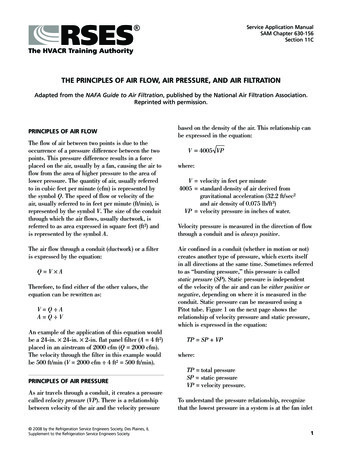
3 Siting the Heat Pump3.2 OrientationThe North face of a building will usuallyhave colder ambient air than any otherside. To ensure maximum efficiencyfrom the Grant Aerona heat pump,position the unit on a warmer side. Inorder of preference, site the unit on aSouth face followed by either SouthEast or South West, then by East orWest. Only install on a North face ifthere is no other alternative.Cooler ambient airNorthEastSouthSiting the Heat PumpFigure 3-2: Location of air source heat pump12
4 Hydraulic DiagramsThe following are examples of suitable systemsIMPORTANT4.1 S-Plan Type - MonovalentThe following system diagramsare only concept drawings andnot detailed engineeringdrawings. They are not intendedto describe complete systems,nor any particular system.Internal wiringcentreProgrammerCylinderStatIt is the responsibility of thesystem designer, not GrantEngineering UK Ltd., todetermine the necessarycomponents for andconfiguration of the particularsystem being designed includingany additional equipment andsafety devices to ensurecompliance with building andsafety code requirements.RoomStatHW FlowCH FlowHeating LoadCH ReturnOutsidewallFlowGrant AeronaHeat PumpHW ReturnHeat sFlexiblepipeIsolatingvalveReturnFigure 4-1: Monovalent system - with S-Plan type controls4.2 Extended S-Plan Type - MonovalentProgrammerInternal wiringcentreCylinderStatCH FlowHW FlowRoomStatHeating LoadRoomStatOutsidewallHeating eHW ReturnCondenserIsolatingvalveCH ReturnFlowGrant AeronaHeat PumpHydraulic DiagramsHeat PumpATCReturn13Figure 4-2: Monovalent system - with extended S-Plan type controls
4 Hydraulic DiagramsIMPORTANTThe following system diagrams areonly concept drawings and notdetailed engineering drawings.They are not intended to describecomplete systems, nor anyparticular system.It is the responsibility of the systemdesigner, not Grant Engineering UKLtd., to determine the necessarycomponents for and configuration ofthe particular system beingdesigned including any additionalequipment and safety devices toensure compliance with buildingand safety code requirements.The following are examples of suitable systems4.3 S-Plan Type - BivalentInternal wiringcentreProgrammerCylinderStatRoomStatHW FlowCH FlowRecommendedmaximum flowtemp. 60 CBoilerMaximumreturn temp. Outside48 CwallRFBoiler CirculatingPump (see note below)FlowGrant AeronaHeat veFlexiblepipeIsolatingvalveHydraulic DiagramsReturn14Figure 4-3: Bivalent system - with boiler manifold and S-Plan type controls!NOTEBoiler circulating pump maybe fittedin Return (between manifold andboiler).Check with boiler manufacturer forguidance on pump location.Auto BypassHW ReturnHeat PumpATCCH ReturnPump delay onBTC must be setfor 2 mins. Referto Section 11.4Heating Load
4.4 Extended S-Plan Type - BivalentInternal wiringcentreProgrammerCylinderStatRoomStatHW FlowCH FlowHeating LoadRecommendedmaximum flowtemp. 60 CBoilerMaximumreturn temp. Outsidewall48 CRFBoiler CirculatingPump (see note urnValveFlexiblepipeRoomStatHW ReturnHeat PumpATCGrant AeronaHeat PumpHeating LoadCH ReturnPump delay onBTC must be setfor 2 mins. Referto Section 11.4CH FlowAuto BypassIsolatingvalveReturnFigure 4-4: Bivalent system - with boiler and extended S-Plan type controls!NOTEHydraulic DiagramsBoiler circulating pump maybe fittedin Return (between manifold andboiler).Check with boiler manufacturer forguidance on pump location.15
4 Hydraulic Diagrams4.5 Buffers TanksIMPORTANTWhen considering the use of a buffer,also consider the space the buffer willtake up – it may not be possible tohouse both a cylinder and a buffer tank.The use of a buffer with the currentAerona heat pump is not necessary inthe majority of installations. However, it ispossible to utilise a buffer if the end-userwishes to store hot water when there isno other demand placed on the system.There are two main considerations whendeciding when and where a buffer tankshould be used.The following system diagramsare only concept drawings andnot detailed engineeringdrawings. They are not intendedto describe complete systems,nor any particular system.It is the responsibility of thesystem designer, not GrantEngineering UK Ltd., todetermine the necessarycomponents for andconfiguration of the particularsystem being designed includingany additional equipment andsafety devices to ensurecompliance with building andsafety code requirements.The following diagrams show both anS-Plan and an extended S-Plan for usewith a buffer tank.!1. It may act as an initial boost when aheating demand is placed on thesystem from cold.NOTEWhen using a buffer tank with theheat pump, the weathercompensation function of the built-inBTC controller is NOT used.2. Storing water for this function willresult in heat losses from the bufferover time, reducing the overall COPand therefore the overall efficiency ofthe heat pump and the system.A cylinder thermostat (withimmersion probe) should be fitted tothe buffer tank. This must be wiredto switch between terminals 1 & 3(the Common and HW terminals) onthe S-Plan controls terminal block inthe heat pump control panel. Referto Figure 8.15 in Section 8 for wiringdiagram. The BTC setting for ‘DHWBOIL TARGET’ should be set to 48 C.4.6 S-Plan with Buffer - MonovalentInternal wiringcentreProgrammerCylinderStatRoomStatCH FlowHWFlowHeating LoadHeat gvalveReturnFigure 4-5: Monovalent system - with Buffer and S-Plan type controls16HW ReturnBuffertankIsolatingvalveCH ReturnFlowGrant AeronaHeat PumpCondenserHydraulic DiagramsOutsidewall
4.7 Extended S-Plan with Buffer - MonovalentInternal wiringcentreProgrammerCylinderStatRoomStatCH FlowHWFlowHeating LoadHeat PumpATCBuffertankHW ReturnFlowGrant AeronaHeat PumpCH urnFigure 4-6: Monovalent system - with Buffer and extended S-Plan type controls!NOTEHydraulic DiagramsThe hydraulic diagrams do not showthe isolation valves, any expansionvessels, pressure relief valves orfilling loops. More information onthese components can be found inSection 7.17
5 System Design CriteriaUnlike a typical condensing oil or gasfired boiler that operates at a flow of70 C and a return of 50 C, a heat pumpoperates with a flow of between 30 Cand 50 C. The return temperature willdepend on the load of the system at agiven point in time.The design of any system in the UK istypically based on 2 parameters.1. That the outside air temperaturecan fall to as low as -3 C and thatthe house comfort temperature willbe 21 C.The BTC incorporated in the heatpump will adjust the outputaccording to the external ambientair temperature but the systemmust be designed in the first placeto meet this maximum demand.2. The second factor to consider isachieving this maximum demandusing much lower watertemperatures than with oil or gasfired appliances.Designing a new system for usewith a low-grade heat source isstraight forward, and assuming theinsulation properties of the dwellingmeets or exceeds current buildingregulations, there should be noissue with achieving the heatdemand.The use of a heat pump in an existingsystem can be straightforward if thefollowing rules are followed.1. The loft has insulation to a depthof 270mm2. Cavity wall insulation has beeninstalled3. The radiators have been changedor upgraded to match the newwater temperatureSystem DesignCriteria4. An accurate heat loss calculationfor each room of the house hasbeen carried out185. All primary and secondary pipeshave been well insulated to preventheat lossIt must be understood that your final design workingtemperature will have an effect on the overall systemefficiency, the COP of the heat pump and thecomplete system. Put simply, the lower your designworking temperature, the better the COP. If you arein any doubt about the suitability of the heatingsystem, stop and seek the advice of a qualifiedheating engineer or experienced system designer.While underfloor heating is the preferredheat emitter, a combination ofunderfloor heating and radiators, orradiators only, works just as efficiently. Itis necessary, however, to calculate thesize of radiator required accurately– if this is not done, the house will failto reach the target temperature and willbe costly to rectify after the installationis complete.Refer to Section 6 to determine the sizeof radiators required for yourinstallation.When tested to BS EN14511, theCoefficient of Performance and HeatOutput for an Air Source Heat Pumpare declared at the test conditions of7 C outside air temperature and 35 Cwater flow temperature.At all other values of outside airtemperature and water flowtemperature the actual Heat Pumpoutput will vary, e.g. the heat output will:a) decrease with lower outside airtemperatures and increase with higheroutside air temperatures at any givenwater flow temperature, andb) decrease with higher water flowtemperatures and increase with lowerwater flow temperatures at any givenoutside air temperatureThe factory fitted 3kW electricimmersion heater should not be addedto the rated output of the Heat Pumpfor sizing/selection purposes. Thiselectric immersion heater serves as aback-up and will only be called intooperation when the heat pump isoperating at low air temperatures.Provided that the Heat Pump is sizedcorrectly for the system, this back-upheater will compensate for any short fallin meeting the design heat load for theproperty at the minimum design airtemperatures.
6 Calculating Radiator SizesExisting SystemsMost existing wet heating systems willuse radiators as emitters. When theoriginal system was installed, theradiators would have been sizedaccording to the manufacturer’sspecifications. Typically, this would havebeen 82ºC flow and 71ºC return withthe connections being flow at the topand return at the opposite bottomcorner.With the advent of condensing boilers,most installations were found to haveoversized radiators and as such, little orno adverse effects were found whenthe system temperatures fell to 70ºCflow and 50ºC return.However, as heat pumps work attemperatures lower than even this, it isimportant that each radiator is checkedagain for its suitability and replaced withone of the correct size/output ifnecessary.Below is a typical radiator correction factor table* and a worked example of sizing radiators for use with a heat pumpA typical heat pump operating to feed radiators will run at a flow temperature of 50ºCand a return temperature of 40ºC – giving a mean water temperature of 45ºC.ºCCorrection Factor50.050100.123150.209In the case of a system using both radiators and Underfloor heating (UFH) a flow of40 C and a return of 30ºC – giving a mean water temperature of 35ºC – would usuallybe preferred.200.304For a living room with a design temperature of 21ºC and heat loss of 1.8kW.250.406300.515350.629From the radiator manufacturers correction factor table: for T 24 C factor 0.406.400.748For a design heat loss of 1.8 kW: the required corrected output is 1.8 / 0.406 4.43kW.450.872501.000551.132Select a radiator from manufacturer’s information that would give 4.43kW output (at75 C mean water temperature) – this will give the required 1.8 kW output at 45 Cmean water temperature produced by the heat pump.601.267651.406701.549751.694The T 45ºC – 21ºC 24ºC.Similarly, for a bedroom with the same design heat loss but design temperature of 18 C.The T 45 C – 18 C 27 C.From the radiator manufacturers correction factor table: for T 27 C factor 0.46.Please advise the customer that, inany case, the radiator will not get‘hot’. The perception may well bethat the system is not workingcorrectly because the radiators areonly ‘warm’.For a design heat loss of 1.8 kW: the required corrected output is 1.8 / 0.46 3.48kW.Thus, select a radiator from manufacturer’s information that would give 3.48kW outputto give the required 1.8 kW output at 45 C mean water temperature.* Where possible reference should be made to radiator manufacturers owninformation for the correction factors for different types of radiator.CalculatingRadiator SizesAs can be seen, the size of radiatorrequired will be larger than conventionalsystems. This can be controlled to anextent by choosing a suitable designwater temperature. The trade off will bea slightly lower COP. As we havealready discussed, the higher therunning temperature, the harder theheat pump has to work to reach thedesired temperature.19
7 Sealed SystemsThe following components are requiredto use the Grant Aerona heat pump aspart of a sealed heating system. Due tothe lack of space these componentsare not located within the heat pump,but have to be fitted external to theunit.a) expansion vessel (of the correct sizeto suit the volume of the system)b) Pressure relief valve – 3 barc) Pressure gauged) Filling loope) TundishThese items may already be installed onthe existing system. If so, they shouldbe checked to ensure the integrity andsuitability of the components beforeproceeding to re-use them.The filling loop can be sited anywhere inthe system, but it must always be sitedwithin visual distance of the pressuregauge. The nominal filling pressure forthe system when cold is 1 bar.Refer to Section 15 for details of theGrant sealed system kits designed foruse with the Grant Aerona heat pumprange.Before filling the system check theexpansion vessel charge pressure. Thisshould be 0.2 – 0.3 bar higher than thecold fill pressure for the system.The expansion vessel can be fitted toeither the flow or return pipes butensure that there is no automatic ormanual valve in line that may preventthe heat pump utilisi
Grant ASHE Air Source Heat Pump Air to Water High Efficiency Heat Pump Range Installation & User Instructions Part No. DOC.93 Rev.00 April 2013 Tested to BS EN 14511 PROVISIONAL COPY. 2 STOP . 8.11 Bivalent Electrical Diagram 30 9 Domestic Hot Water 31 9.1 Temperature Control 31 9.2 Heat Pump Cylinders 31 9.3 Temperature Boost 31