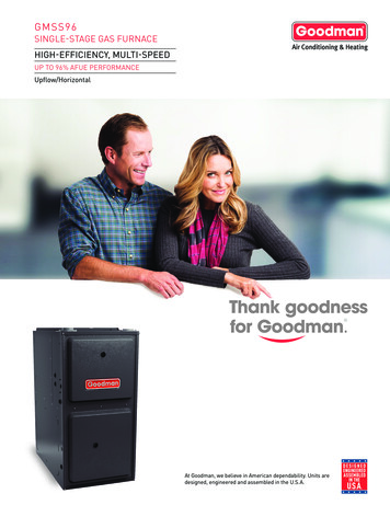
Transcription
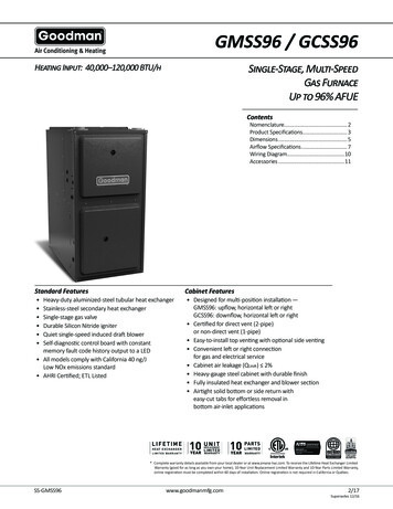
GMSS96 / GCSS96Single-Stage, Multi-SpeedGas FurnaceUp to 96% AFUEHeating Input: 40,000–120,000 BTU/hContentsNomenclature.2Product Specifications. 3Dimensions.5Airflow Specifications.7Wiring Diagram.10Accessories.11Standard FeaturesCabinet Features Designed for multi-position installation —GMSS96: upflow, horizontal left or rightGCSS96: downflow, horizontal left or right Certified for direct vent (2-pipe)or non-direct vent (1-pipe) Easy-to-install top venting with optional side venting Convenient left or right connectionfor gas and electrical service Cabinet air leakage (QLeak) 2% Heavy-gauge steel cabinet with durable finish Fully insulated heat exchanger and blower section Airtight solid bottom or side return witheasy-cut tabs for effortless removal inbottom air-inlet applicationsHeavy-duty aluminized-steel tubular heat exchangerStainless-steel secondary heat exchangerSingle-stage gas valveDurable Silicon Nitride igniterQuiet single-speed induced draft blowerSelf-diagnostic control board with constantmemory fault code history output to a LED All models comply with California 40 ng/JLow NOx emissions standard AHRI Certified; ETL Listed* Complete warranty details available from your local dealer or at www.amana-hac.com. To receive the Lifetime Heat Exchanger LimitedWarranty (good for as long as you own your home), 10-Year Unit Replacement Limited Warranty and 10-Year Parts Limited Warranty,online registration must be completed within 60 days of installation. Online registration is not required in California or Québec.SS-GMSS96www.goodmanmfg.com2/17Supersedes 12/16
randEngineeringG - Goodman BrandMajor / Minor Revisions* Not used for inventory control.ConfigurationNOxM - Upflow/HorizontalN - Low NOxC - Downflow/HorizontalCabinet WidthMotorB - 17½”C - 21"D - 24½"V - Variable Speed ECM / ComfortNetE - Multi-Speed ECMMaximum CFMS - Single SpeedGas Valve2 - 800 CFM4 - 1600 CFM3 - 1200 CFM5 - 2000 CFMM - ModulatingMBTU/hC - Two- StageS - Single Stage040 - 40,000 BTU/h060 - 60,000 BTU/hAFUE97 - 97% AFUE120 - 120,000 BTU/h96 - 96% AFUE92 - 92% AFUE2www. goodmanmfg.comSS-GMSS96
GMSS96 Product 05DNAHigh Fire 0High Fire 0Heating DataAFUE²96969696969696Temperature Rise Range ( F)25 - 5535 - 6535 - 6525 - 5525 - 5530 - 6035 - 65Vent Diameter³2" - 3"2" - 3"2" - 3"2" - 3"2" - 3"2" - 3"3"No. of Burners2344456Circulator BlowerAvailable AC @ 0.5" ESP1.5 - 31.5 - 31.5 - 31.5 - 43-53-53-5Size (D x W)10" x 8"10" x 8"10" x 8"10" x 10"11" x 10"11" x 10"11" x 11"Horsepower @ 1075 RPM⅓⅓½½¾¾¾Speed4444444Min. Circuit Ampacity⁴9.69.612.811.713.713.713.7Max. Overcurrent Device (amps)⁵15151515151515Shipping Weight (lbs)111114116139140142154Electrical Data¹²³⁴⁵Natural Gas BTU/hDOE AFUE based upon Isolated Combustion System (ICS)Installer must supply one or two PVC pipes: one for combustion air (optional) and one for the flue outlet (required).Vent pipe must be either 2" or 3" in diameter, depending upon furnace input, number of elbows, length of runand installation (1 or 2 pipes). The optional Combustion Air Pipe is dependent on installation/code requirementsand must be 2" or 3" diameter PVC.Minimum Circuit Ampacity (1.25 x Circulator Blower Amps) ID Blower amps. Wire size should be determinedin accordance with National Electrical Codes. Extensive wire runs will require larger wire sizes.Maximum Overcurrent Protection Device refers to maximum recommended fuse or circuit breaker size.May use fuses or HACR-type circuit breakers of the same size as noted.Notes All furnaces are manufactured for use on 115 VAC, 60 Hz, single-phase electrical supply. Gas Service Connection ½" FPT Important: Size fuses and wires properly and make electrical connections in accordance with theNational Electrical Code and/or all existing local codes. For bottom return: Failure to unfold flanges may reduce airflow by up to 18%. This could result in performanceand noise issues. For servicing or cleaning, a 24" front clearance is required. Unit connections (electrical, flue and drain)may necessitate greater clearances than the minimum clearances listed above. In all cases, accessibilityclearance must take precedence over clearances from the enclosure where accessibility clearances are greater.SS-GMSS96www.goodmanmfg.com3
GCSS96 CNAGCSS961005CNAGCSS961205DNAHigh Fire Input¹40,00060,00080,000100,000120,000High Fire Output¹38,40057,60076,80095,000114,000Heating DataAFUE²9696969595Temperature Rise Range ( F)25 - 5535 - 6535 - 6540 - 7045 - 75Vent Diameter³2" - 3"2" - 3"2" - 3"2" - 3"3"No. of Burners23456Circulator BlowerAvailable AC @ 0.5" ESP1.5 - 31.5 - 32.5 - 43-53-5Size (D x W)10" x 8"10" x 8"10" x 10"11" x 10"11" x 11"Horsepower @ 1075 RPM⅓⅓½¾¾Speed44444Electrical DataMin. Circuit Ampacity⁴9.69.611.713.713.7Max. Overcurrent Device (amps)⁵1515151515Shipping Weight (lbs)111114139142154¹²³⁴⁵Natural Gas BTU/hDOE AFUE based upon Isolated Combustion System (ICS)Installer must supply one or two PVC pipes: one for combustion air (optional) and one for the flue outlet (required). Vent pipe must be either 2” or 3” in diameter, dependingupon furnace input, number of elbows, length of run and installation (1 or 2 pipes). The optional Combustion Air Pipe is dependent on installation/code requirements and mustbe 2” or 3” diameter PVC.Minimum Circuit Ampacity (1.25 x Circulator Blower Amps) ID Blower amps. Wire size should be determined in accordance with National Electrical Codes.Extensive wire runs will require larger wire sizes.Maximum Overcurrent Protection Device refers to maximum recommended fuse or circuit breaker size. May use fuses or HACR-type circuit breakers of the same size as noted.Notes All furnaces are manufactured for use on 115 VAC, 60 Hz, single-phase electrical supply. Gas Service Connection ½” FPT Important: Size fuses and wires properly and make electrical connections in accordance with the National Electrical Code and/or all existing local codes. For bottom return: Failure to unfold flanges may reduce airflow by up to 18%. This could result in performance and noise issues. For servicing or cleaning, a 24” front clearance is required. Unit connections (electrical, flue and drain) may necessitate greater clearances than the minimum clearances listedabove. In all cases, accessibility clearance must take precedence over clearances from the enclosure where accessibility clearances are greater.4www. goodmanmfg.comSS-GMSS96
GMSS96 DimensionsAirDischargeAirDischarge28¾Air Intake2" Pipe6½2¾A2⅝2C¾BCenter DimpleFor AlternateAir Intake Pipe3" OD HoleHigh-VoltageElectrical OutletLeft-SideDrain TrapExterior Holes6½1⅞¾¾219½Vent/ Flue Pipe2" PVCAlternateVent/ FlueLocationRight-SideDrain TrapExterior HolesHigh-VoltageElectrical OutletStandardGas SupplyLocationAlternateGas �51½LEFT SIDE VIEW51⅞2⅜2½Low-voltageElectrical Outlet1⅜1⅞RIGHT SIDE VIEW2⅜2½Low-VoltageElectrical OutletDUnfolded FlangesCondensate DrainTrap ExteriorConnection(Right or Left Side)¾ PVC23⅞FRONT VIEW22EFolded FlangesUnfolded Flanges23½Folded �"20⅞"Minimum Clearances to Combustible 0"0"3"C0"1"Horizontal6"0"3"C0"6"C If placed on combustible floor, the floor MUST be wood ONLY.SS-GMSS96www.goodmanmfg.com5
GCSS96 nate Vent/Low-VoltageElectrical Outlet1½Low-VoltageElectrical Outlet14Alternate GasAlternateGas SupplyHigh-VoltageElectrical Outlet25⅛34½25⅛14⅞14¾14¾11⅜4⅛Drain Trap HolesStandard Drain Trap11⅜6⅞6⅞28¾High-VoltageElectrical OutletDUnfolded Flanges22½3½2⅝Right Side ExteriorDrain Trap HolesFront ViewAirReturnModel20⅛Folded Flanges2EFolded FlangesAirDischarge18⅛Unfolded FlangesRight-Side 21½"23"Minimum Clearances to Combustible ow0"0"3"NC0"1"Horizontal6"0"3"C0"6"C If placed on combustible floor, the floor MUST be wood ONLY.NC For installation on non-combustible floors only. A combustible floor sub-base must be used for installations on combustible flooring.6www. goodmanmfg.comSS-GMSS96
GMSS96 Airflow Data(CFM & Temperature Rise vs. External Static Pressure)ModelMotorSpeedHighMedGMSS960402BNA Med-LoExternal Static Pressure, (Inches Water 958854MedGMSS960603BNA S960803BNA 51,941371,8501,7531,651MedGMSS960804CNA Med-LoMedGMSS960805CNA 8511,675531,6051,5141,410GMSS961005CNA Med-LoLowHighMedGMSS961205DNA ,345N/A1,311N/A1,272N/A1,2151,1591,066at 0.5" ESPNotes CFM in chart is without filter(s). Filters do not ship with this furnace, but must be provided by the installer. If the furnace requires two return filters,this chart assumes both filters are installed. All furnaces ship as high-speed cooling and medium-speed heating. Installer must adjust blower cooling & heating speed as needed. For most jobs, about 400 CFM per ton when cooling is desirable. INSTALLATION IS TO BE ADJUSTED TO OBTAIN TEMPERATURE RISE WITHIN THE RANGE SPECIFIED ON THE RATING PLATE. This chart is for information only. For satisfactory operation, external static pressure should not exceed value shown on the rating plate.The shaded area indicates ranges in excess of maximum static pressure allowed when heating. The above chart is for U.S. furnaces installed at 0-2000 feet. At higher altitudes, a properly derated unit will have approximately the sametemperature rise at a particular CFM, while ESP at the CFM will be lower.Minimum Filter SizesGMSS960402BNAFilter Size (in²) (Qty)GMSS960603BNAGMSS960803BNAGMSS960804CNA(1) 16xX 25 (side or bottom)GMSS960805CNAGMSS961005CNAGMSS961205DNA(1) 20 x 25 (bottom) or (2) 16 x 25 (side)Note: Other size filters of equal or greater dimensions may be used. Filters may also be centrally located.SS-GMSS96www.goodmanmfg.com7
GCSS96 Airflow Data(CFM & Temperature Rise vs. External Static .5889408724182943815MedGCSS960402BNA 965GCSS960603BNA Med-LoMedGCSS960804CNA Med-LoMedGCSS961005CNA /A1,264N/A1,2081,1531,061GCSS961205DNA Med-LoLow¹External Static Pressure, (Inches Water Column)MotorSpeedat 0.5" ESPNotes CFM in chart is without filter(s). Filters do not ship with this furnace, but must be provided by the installer. If the furnace requires two return filters,this chart assumes both filters are installed. All furnaces ship as high-speed cooling and medium-speed heating. Installer must adjust blower cooling & heating speed as needed. For most jobs, about 400 CFM per ton when cooling is desirable. INSTALLATION IS TO BE ADJUSTED TO OBTAIN TEMPERATURE RISE WITHIN THE RANGE SPECIFIED ON THE RATING PLATE. This chart is for information only. For satisfactory operation, external static pressure should not exceed value shown on the rating plate.The shaded area indicates ranges in excess of maximum static pressure allowed when heating. The above chart is for U.S. furnaces installed at 0-2000 feet. At higher altitudes, a properly derated unit will have approximately the sametemperature rise at a particular CFM, while ESP at the CFM will be lower.Minimum Filter SizesGCSS960402BNAFilter Size (in²) (Qty)GCSS960603BNAGCSS960804CNA(2) 10 x 20 or (1) 16 x 25 (top return)GCSS961005CNAGCSS961205DNA(1) 14 x 20 (bottom) or (1) 20 x 25 (top return)Note: Other size filters of equal or greater dimensions may be used. Filters may also be centrally located.8www. goodmanmfg.comSS-GMSS96
405060700600 CFM90100200022002400 CFM180016001400OUTPUTBTU/HRx 1000Output BTU/hx 30CFM x 1.08140BTUBTU/hOUTPUT1.08x RISEOutput CFMCFM xx1.08x RiseBTU OUTPUTBTU/H Output CFMRISERise s.Temperature Rise150Temperature Rise Range Chart9TEMPERATURERISETemperature Rise
Wiring DiagramYBKBLFUSE3GY21PKOR654987BL121110YLGRORGY24V THERMOSTAT CID BLOWERPRESSURESWITCHPS (10)NOCPSO (4)TOMICROYGASVALVEM1FRONT COVERPRESSURE SWITCHHLI (7)WHLO (1)AUXILIARYLIMIT CONTROLSRAUTO RESETPRIMARYLIMITCONTROLRO2 (11)RO1 (5)MANUAL RESET ROLLOUTLIMIT CONTROL(S)(SINGLE CONTROL ON 40K BTU)24 VACBRRDC2 WNOTH (3)40 VATRANSFORMERWHBR-HATHELINE-HJUNCTION BOXPUGNDDOORSWITCHBKWHWHINDUCED DRAFTBLOWERPUBLYLORWHMA NUAL R ESET RO LLO UT L IMIT CO NTR O L(S)( SINGLE CONTROL ON 40K BTU )C2GNDBLGR1 FLASHGYCGAS VALVEFRONT COVERPRESSURE SWITCHNFLAMESENSORGRGNDBKDISCONNECTHI VOLTAGE (115V)2 FLASHES PRESSURE SWITCH STUCK CLOSEDHI VOLTAGE FIELD3 FLASHES PRESSURE SWITCH STUCK OPEN4 FLASHES OPEN HIGH LIMITJUNCTION5 FLASHES FLAME SENSE WITHOUT GAS VALVETERMINAL6 FLASHES OPEN ROLLOUT8 FLASHES 8 FLASHES CHECK IGNITER OR IMPROPER GROUNDINGCONTINUOUS/RAPID FLASHES REVERSED 115 VAC POLARITYPK PINKBR BROWNWH WHITEBL BLUEGY GRAYRD REDGNDLOW VOLTAGE FIELD SYSTEM LOCKOUT (RETRIES EXCEEDED)7 FLASHES 7 FLASHES LOW FLAME SIGNALNWARNING:DISCONNECT POWER BEFORESERVICING.WIRING TO UNIT MUST BEPROPERLY POLARIZED AND GROUNDED.LOW VOLTAGE (24V) CONTROL FAILURECOLOR CODES:YL YELLOWOR ORANGEPU PURPLEGN GREENBK BLACKGNDWHNOSTEADY ON NORMAL OPERATIONOFFJUNCTIONBOXBRMILINTERNAL TOINTEGRATED CONTROLPLUG CONNECTIONLTO 115 VAC / 1Ø / 60HZPOWER SUPPLY WITHOVERCURRENT PROTECTIONDEVICE24 VACHUMIDIFIER2 CIRCUITCONNECTORHOTSURFACEIGNITERRDPKDISCONNECTTO 115VAC/ 1 Ø /60 HZ POWER SUPPLY WITHOVERCURRENT PROTECTION DEVICEORCID BLOWERPRESSURESWITCHWARNING:DISCONNECT POWERBEFORE SERVICING.WIRING TO UNITMUST BEPROPERLYPOLARIZEDAND GROUNDED.WHAUTO RE SETPRIMA RY LIMITCO NTR O LNOELECTRONICAIR CLEANEREAC-HBURNER COMPARTMENTCIRCULATORBLWRINTEGRATED CONTROL MODULECOOLBLOWER COMPARTMENTRDLINE NEUTRALSGYAUXILIARY TED CONTROL MODULEGRRDYLWHPKRDHOT SURFACEIGNITERIGNBKCIRCULATORBLOWERBR115 VACFSWHBK (HI)BL (MED)OR (MED LOW)RD (LOW)BRXFMR-HFLAME SENSOR1HEAT-HLINE-HGNDWHPK2115 VAC HOT AND PARK TERMINALSCOOL-H115 VAC NEUTRALTERMINALSXFMR-HDIAGNOSTICLEDEQUIPMENT GNDFIELD GNDFIELD SPLICESWITCH (TEMP.)IGNITERSWITCH (PRESS.)OVERCURRENTPROT. DEVICEHigh Voltage: Disconnect all power before servicing or installing this unit. Multiple powersources may be present. Failure to do so may cause property damage, personal injury, or death.RGGNDGND (8)MVC (9)WarningC40 VATRANSFORMERINTEGRATEDCONTROL MODULEHUMIDIFIERTR (6) 24 VAC115 VAC24V THERMOSTATCONNECTIONSBLOWERCOMPARTMENTDOOR SWITCH(OPEN WHENDOOR OPEN)GYWiring is subject to change. Alwaysrefer to the wiring diagram on theunit for the most up-to-date wiring.OR24 VACHUMIDIFIERNOTES:1. SET HEAT ANTICIPATOR ON ROOM THERMOSTAT AT 0.7 AMPS.2. MANUFACTUR'S SPECIFIED REPLACEMENT PARTS MUST BE USED WHEN SERVICING.3. IF ANY OF THE ORIGINAL WIRE AS SUPPLIED WITH THE FURNACE MUST BE REPLACED, IT MUST BE REPLACED WITH WIRING MATERIALHAVING A TEMPERATURE RATING OF AT LEAST 105 C. USE COPPER CONDUCTORS ONLY.4. BLOWER SPEEDS SHOULD BE ADJUSTED BY INSTALLER TO MATCH THE INSTALLATION REQUIREMENTS SOAS TO PROVIDE THE CORRECT HEATING TEMPERATURE RISE AND THE CORRECT COOLING CFM.5. UNIT MUST BE PERMANENTLY GROUNDED AND CONFORM TO N.E.C. AND LOCAL CODES.0140F01908-A10www. goodmanmfg.comSS-GMSS96
05CNAGMSS961205DNACVENT-2Concentric Vent Kit (2") ---CVENT-3Concentric Vent Kit (3") CFSB17Downflow Sub-Base 17.5"---------------------CFSB21Downflow Sub-Base 21"---------------------CFSB24Downflow Sub-Base 24"---------------------RF000142 ------0170K00000SDrain Kit -Horizontal Left Vertical FlueExternal Filter Rack with 16"x25"Permanent FilterFlush Mount Vent Kit - 3" or 2"0170K00001SFlush Mount Vent Kit - 2" AFE18-60AFossil Fuel (Dual Fuel) Kit /AN/AN/AN/AEFR02HASFKHigh-Altitude Natural Gas KitHASFKHigh-Altitude LP Gas Kit --- ---HASFK-4,5,6 HASFK-5,6 HASFK-5,6LPLP03Low LP Gas Pressure SwitchLPM-07LP Conversion Kits FTK04Twinning Kit GCSS960402BNAGCSS960603BNAModelDescription GCSS960804CNAGCSS961005CNAGCSS961205DNA CVENT-2Concentric Vent Kit (2") ---CVENT-3Concentric Vent Kit (3") CFSB17Downflow Sub-Base 17.5" ---------CFSB21Downflow Sub-Base 21"------ ---CFSB24Downflow Sub-Base 24"------------ RF000142--------------- ------0170K00000SDrain Kit -Horizontal Left Vertical FlueExternal Filter Rack with 16"x25"Permanent FilterFlush Mount Vent Kit - 3" or 2" 0170K00001SFlush Mount Vent Kit - 2" ---AFE18-60AFossil Fuel (Dual Fuel) Kit HASFKHigh-Altitude Natural Gas titude LP Gas KitHASFK-5HASFK-5HASFK-5HASFK-4HASFK-4LPLP03Low LP Gas Pressure Switch LPM-07LP Conversion Kits FTK04Twinning Kit EFR02SS-GMSS96www.goodmanmfg.com11
NotesGoodman Manufacturing Company, L.P., reserves the right to discontinue, or change at any time, specifications or designswithout notice or without incurring obligations. 2015 Goodman Manufacturing Company, L.P. Houston, Texas12www. goodmanmfg.comSS-GMSS96
Gas Furnace Up to 96% AFUE GMSS96 / GCSS96 Heating Input: 40,000-120,000 BTU/h SSGMSS96 www.goodanfgo / . Brand Engineering G - Goodman Brand Major / Minor Revisions * Not used for inventory control. Configuration NOx M - Upflow/Horizontal N - Low NOx C - Downflow/Horizontal . NC For installation on non-combustible floors only. A .