Transcription
ServiceInstructionsModels listedon pages 4-680% GDT, GMP, GMPE, GMPH,GMPV, GMT, GMTH, GPD90% GMNT, GMNTE, GMNV, GMPN, GSM,GSMS, GSUThis Forced Air Central Unit Design Complies WithRequirements Embodied in The American NationalStandard / National Standard of Canada Shown Below.ANSI Z21.47 CSA-2.3 Central Furnaces This manual is to be used by qualified, professionally trained HVAC technicians only.Goodman does not assume any responsibility for property damage or personal injurydue to improper service procedures or services performed by an unqualified person.Copyright 2000-2007 Goodman Manufacturing Company, L.P.RS6610003January 2007
TABLE OF CONTENTSIMPORTANT INFORMATION . 2-3SERVICING . 30-56PRODUCT INFORMATION . 4-12SERVICING TABLE OF CONTENTS . 32SPECIFICATIONS . 13-23TROUBLESHOOTING . 46DIMENSIONS . 24-27WIRING DIAGRAMS . 58-77MAINTENANCE . 28IMPORTANT INFORMATIONPride and workmanship go into every product to provide our customers with quality products. It is possible, however,that during its lifetime a product may require service. Products should be serviced only by a qualified servicetechnician who is familiar with the safety procedures required in the repair and who is equipped with the proper tools,parts, testing instruments and the appropriate service manual. REVIEW ALL SERVICE INFORMATION IN THEAPPROPRIATE SERVICE MANUAL BEFORE BEGINNING REPAIRS.IMPORTANT NOTICES FOR CONSUMERS AND SERVICERSRECOGNIZE SAFETY SYMBOLS, WORDS AND LABELSWARNINGTHIS UNIT SHOULD NOT BE CONNECTED TO, OR USED IN CONJUNCTION WITH, ANY DEVICES THAT ARE NOT DESIGN CERTIFIED FOR USE WITH THIS UNIT OR HAVE NOT BEENSERIOUS PROPERTY DAMAGE OR PERSONAL INJURY, REDUCED UNIT PERFORMANCE AND/OR HAZARDOUS CONDITIONS MAY RESULTFROM THE USE OF DEVICES THAT HAVE NOT BEEN APPROVED OR CERTIFED BY GOODMAN.TESTED AND APPROVED BY GOODMAN.WARNINGTO PREVENT THE RISK OF PROPERTY DAMAGE, PERSONAL INJURY, OR DEATH,DO NOT STORE COMBUSTIBLE MATERIALS OR USE GASOLINE OR OTHERFLAMMABLE LIQUIDS OR VAPORS IN THE VICINITY OF THIS APPLIANCE.W ARNINGG OODMAN W ILL NOT BE RESPONSIBLE FOR ANY INJURY OR PROPERTY DAM AGE ARISING FROM IMPROPER SERVICE OR SERVICE PROCEDURES.I F YOU INSTALL OR PERFORM SERVICE ON THIS UNIT, YOU ASSUME RESPONSIBILITY FOR ANY PERSONAL INJURY OR PROPERTY DAMAGE WHICHMAY RESULT. M ANY JURISDICTIONS REQUIRE A LICENSE TO INSTALL OR SERVICE HEATING AND AIR CONDITIONING EQUIPMENT.W ARNINGHIGH VOLTAGED ISCONNECT ALL POWERBEFORE SERVICING OR INSTALLING THIS UNIT.TO DO SO MAY CAUSE PROPERTY DAM AGE, PERSONAL INJURY OR DEATH.2M ULTIPLEPOWER SOURCES MAY BE PRESENT.F AILURE
IMPORTANT INFORMATIONWARNINGIF THE INFORMATION IN THESE INSTRUCTIONS IS NOT FOLLOWEDEXACTLY, AFIRE OR EXPLOSION MAY RESULT CAUSING PROPERTY DAMAGE, PERSONALINJURY OR LOSS OF LIFE.–DO NOT STORE OR USE GASOLINE OR OTHER FLAMMABLE VAPORS ANDLIQUIDS IN THE VICINITY OF THIS OR ANY OTHER APPLIANCE.–WHAT TO DO IF YOU SMELL GAS: DO NOT TRY TO LIGHT ANY APPLIANCE. DO NOT TOUCH ANY ELECTRICAL SWITCH; DO NOT USE ANYPHONE IN YOUR BUILDING. IMMEDIATELY CALL YOUR GAS SUPPLIER FROM A NEIGHBOR’SPHONE.FOLLOW THE GAS SUPPLIER’S INSTRUCTIONS. IF YOU CANNOT REACH YOUR GAS SUPPLIER, CALL THE FIRECARBON MONOXIDE POISONING HAZARDSpecial Warning for Installation of Furnace or Air Handling Units inEnclosed Areas such as Garages, Utility Rooms or Parking AreasDEPARTMENT.– INSTALLATION AND SERVICE MUST BE PERFORMED BY A QUALIFIED INSTALLER,SERVICE AGENCY OR THE GAS SUPPLIER.WARNINGSHOULD OVERHEATING OCCUR ORTHE GAS SUPPLY FAIL TO SHUT OFF, TURNCarbon monoxide producing devices (such as an automobile, spaceheater, gas water heater, etc.) should not be operated in enclosed areassuch as unventilated garages, utility rooms or parking areas because ofthe danger of carbon monoxide (CO) poisoning resulting from the exhaustemissions. If a furnace or air handler is installed in an enclosed area suchas a garage, utility room or parking area and a carbon monoxide producingdevice is operated therein, there must be adequate, direct outsideventilation.OFF THE MANUAL GAS SHUTOFF VALVE EXTERNAL TO THE FURNACE BEFORETURNING OFF THE ELECTRICAL SUPPLY.This ventilation is necessary to avoid the danger of CO poisoning whichcan occur if a carbon monoxide producing device continues to operate inthe enclosed area. Carbon monoxide emissions can be (re)circulatedthroughout the structure if the furnace or air handler is operating in anymode.CO can cause serious illness including permanent brain damage or death.B10259-216To locate an authorized servicer, please consult your telephone book or the dealer from whom you purchased thisproduct. For further assistance, please contact:CONSUMER INFORMATION LINEGOODMAN BRAND PRODUCTSTOLL FREE 1-877-254-4729 (U.S. only)email us at: customerservice@goodmanmfg.comfax us at: (731) 856-1821(Not a technical assistance line for dealers.)Outside the U.S., call 1-713-861-2500.(Not a technical assistance line for dealers.) Your telephone company will bill you for the call.3
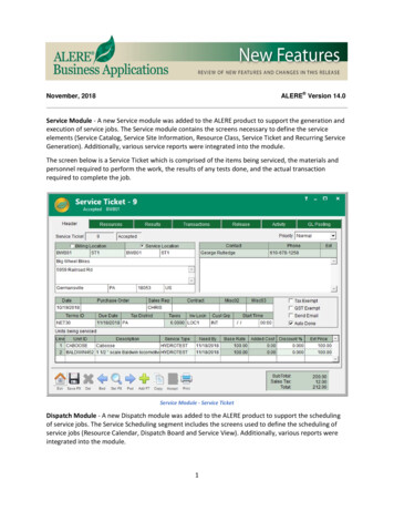
PRODUCT IDENTIFICATIONNOMENCLATUREGMT0703*BRANDG: Goodman Gas FurnaceAIR FLOW DIRECTIONEngineeringRevisionM: Multi-PositionD: Dedicated DownflowP: 80% Single StageS: 92% Single StageMAXIMUM CFM@ 0.5" ESPDESCRIPTIONT:P:D:M:3: 1,2004: 1,6005: 2,00080% Tubular Heat Exchanger80% Non-Tubular Heat ExchangerDownflow PositionMulti-Position (Upflow/Horizontal)KBTUH045: 45,000050: 50,000060: 60,000070: 70,000075: 75,000090: 90,000100: 100,000115: 115,000125: 125,000140: 60-3GSM080-4GSM100-4GSMS060-3GSMS080-4GSMS100-4
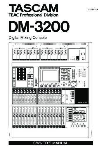
PRODUCT IDENTIFICATIONNOMENCLATUREGMPV0703*BRANDG: Goodman Gas FurnaceAIR FLOW DIRECTIONEngineeringRevisionM: Multi-PositionD: Dedicated DownflowMAXIMUM CFM@ 0.5" ESPDESCRIPTION3: 1,2004: 1,6005: 2,000T: 80% Tubular Heat ExchangerP: 80% Non-Tubular Heat ExchangerBLOWER TYPEKBTUHV: Variable Speed - Single StageE: Variable Speed - Two StageH: High Air Flow045: 45,000070: 70,000075: 75,000090: 90,000100: 100,000115: 115,000125: 125,000140: H115-5GMPH050-3GMPH075-4GMPH080-5GMPH120-55
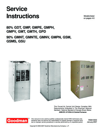
PRODUCT IDENTIFICATIONNOMENCLATUREMGPN0703*BRANDG: Goodman Gas FurnaceAIR FLOW DIRECTIONEngineeringRevisionM: Multi-PositionD: Dedicated DownflowS: 90 Condensing FurnaceMAXIMUM CFM@ 0.5" ESPDESCRIPTION3: 1,2004: 1,6005: 2,000M: Upflow/HorizontalP: PositionN: 92.6% CondensingBLOWER TYPEKBTUHN: 90% Condensing FurnaceS: Single Stage OperationT: Single Stage - Tubular Heat ExchangerTE: Two-stage/Variable Speed - Tubular Heat Exchanger040: 40,000060: 60,000080: 80,000100: 100,000120: GMPN100-4GMPN120-5GSMS060-3GSMS080-4GSMS100-4
PRODUCT IDENTIFICATIONModel #DescriptionGDT80% AFUE. Downflow application, single stage, induced draft motor,psc multi-speed motor, integrated control module with diagnostics,hot surface ignition system, multiple roll out switches, pressureswitches, aluminized tubular steel heat exchanger, aluminized inshotburners.GMT80% AFUE. Multi-position (Upflow, Horizontal Left or Right), singlestage, induced draft motor, psc multi-speed motor, integrated controlmodule with diagnostics, hot surface ignition system, roll outswitches, pressure switches, aluminized tubular steel heatexchanger and inshot burners.GMTH80% AFUE. Multi-position (Upflow, Horizontal Left or Right), singlestage, multi-position induced draft motor, psc multi-speed motor,integrated control module with diagnostics, hot surface ignitionsystem, multiple roll out switches, pressure switches, a rotatingcombustion blower motor that allows venting the furnace through thetop panel, right hand side panel and left hand side panel, aluminizedsteel heat exchanger and inshot burners.GMP80% AFUE. Multi-position (Upflow, Downflow, Horizontal Left orRight), single stage, induced draft motor, psc multi-speed motor,integrated control module with diagnostics, hot surface ignitionsystem, multiple roll out switches, pressure switches, aluminizedsteel heat exchanger, aluminized inshot burners, LoNox.GMPE80% AFUE. Multi-position (Upflow, Downflow, Horizontal Left orRight), two-stage gas valve, multi-position induced draft motor,variable-speed ECM motor, integrated control module withdiagnostics, hot surface ignition system, multiple roll out switches,outlet air limit switch and LoNox approved.GMPH80% AFUE. Multi-position (Upflow, Downflow, Horizontal Left orRight), single stage, induced draft motor, psc multi-speed motor,integrated control module with diagnostics, hot surface ignitionsystem, multiple roll out switches, pressure switches, aluminizedsteel heat exchanger and inshot burners.GMPV80% AFUE. Multi-position (Upflow, Downflow, Horizontal Left orRight), single stage, induced draft motor, variable speed ECM motor,integrated control module with diagnostics, hot surface ignitionsystem, multiple roll out switches, pressure switches, aluminizedsteel heat exchanger, aluminized inshot burners.GPD80% AFUE. Downflow application. Single stage, induced draft motor,psc multi-speed motor, integrated control module with diagnostics,hot surface ignition system, multiple roll out switches, pressureswitches, aluminized steel heat exchanger, aluminized inshotburners, LoNox, gas and electric connections can be made on theleft or right side.7
PRODUCT IDENTIFICATIONModel #GMNV90% AFUE. Multi-position (Upflow or Horizontal), single stage,induced draft motor, variable speed motor, hot surface ignitionsystem, roll out switch, pressure switch, aluminized steel heatexchanger and aluminized inshot burners.GMNT92.6% AFUE. Multi-position (Upflow, Horizontal Left or Right),induced draft, psc multi-speed motor, integrated control module withdiagnostics, hot surface ignition system, multiple roll out switches,pressure switches, multi-position induced draft motor, tubular heatexchanger (primary) and aluminized inshot burners.GMNTE92.6% AFUE. Multi-position (Upflow, Horizontal Left or Right), twostage gas valve, two-stage induced draft motor, variable speedblower motor, integrated control module with diagnostics, hot surfaceignition system, roll out switches, pressure switches, tubular heatexchanger (primary) and aluminized inshot burners, LoNOx.GMPN92.6% AFUE. Multi-position (Upflow, Downflow, Horizontal), singlestage, induced draft motor, psc multi-speed motor, integrated controlmodule with diagnostics, hot surface ignition system, multiple roll outswitches, pressure switches, aluminized steel heat exchanger andaluminized inshot burners.GSMGSMSGSU8Description92.6% AFUE. Multi-position (Upflow, Horizontal), two-stage gasvalve, two-stage induced draft motor, psc multi-speed motor,integrated control module with diagnostics, hot surface ignitionsystem, multiple roll out switches, pressure switches, aluminized92.6% AFUE. Multi-position (Upflow, Horizontal Left or Right), singlestage application, induced draft, psc multi-speed motor, integratedcontrol module with diagnostics, hot surface ignition system, multipleroll out switches, pressure switches, aluminized steel heatexchanger and inshot burners.92.6% AFUE. (Upflow Only), two0stage gas valve, induced draftmotor, psc multi-speed motor, integrated control module withdiagnostics, hot surface ignition system, flame roll-out switch,pressure switches, aluminized stell heat exchanger, stainless steelsecondary heat exchanger and aluminized inshot burners.
nventric Vent KitXGMPVSBMGPDCombustible Floor BaseXSVB-80XSidewall VentingXHA-02XOrifices (6 ea./PACK)(0.43) B2589901 / (0.44) B2589902(0.45) B2589903 / (0.46) B2589904(0.47) B2589905 / (0.48) B2589906(0.49) B2589907 / (0.55) B2589900(0.56) B2589908 / (0.57) B2589909(0.58) B2589910XGMTHLPT-00/00AXXHoneywell Spring B1880006White-Rodgers Spring B1880007Orifice (0.55) B4089955XXLPT-01/01AXHoneywell Spring B1880006White-Rodgers Spring B1880007Orifice (1.25) B40899125GMPHLPM-04GDT2-Stage LP Gas Valve B1282624Honeywell Spring B1880006White-Rodgers Spring B1880007Orifice (1.25) B25899125XXLPM-03XXLP Gas Valve B1282618Honeywell Spring B1880006White-Rodgers Spring B1880007Orifice (1.25) B25899125XXLPM-01XXHoneywell Spring B1880006White-Rodgers Spring B1880004Orifice (0.55) l Spring B1880006White-Rodgers Spring B1880007Orifice (0.55) XXXXXXNot used in this application9
PRODUCT IDENTIFICATIONLIGHTING INSTRUCTIONSGMTFOR YOUR SAFETY READ BEFORE OPERATINGWARNING:Improperent, alteration, servicecause injury or propthe user's informationthis furnace. For assB. BEFORE OPERATING smell aroundcontrol switch or knob. Never usetools. If the gas control switch or knobsmell next to the floor because some gasForce or attempted repair may result invice agency or thegas supplier.WHAT TO DO IF YOU SMELL GASThis furnace must beDo not touch any electric switch;the control system and any gas controlwhich has been under water.ce with the manufacturers instructionsthe gas suppliers instructions.OPERATING INSTRUCTIONSgas, go to the next step.8. Move the gas control switch or knobPGB & PGJFor outdoor install-9. Replace control access panel.WARNING:5. Remove control access panel.6. Move the gas control switch or knobto "OFF".follow the instructions "To Turn Off Gastechnician or gas supplier.If not ins-acturer's instructions,this product couldexpose you to substances in fuel combustion which can causeess and which areGAS CONTROLGAS CONTROLTO TURN OFF GAS TO APPLIANCE4. Move the gas control switch or knobto "OFF". Do not force.appliance if service is to be performed.cancer, birth defectsor other reproductiveharm.This product containscontains a chemical5. Replace control access panel.3. Remove control access panel.FOR YOUR SAFETYDo not store or use gasoline orother flammable vapors and liquids in the vicinity of thisor any other appliance.10
PRODUCT IDENTIFICATIONLIGHTING INSTRUCTIONSGMP, GMPE, GMPN, GMNT, GMTHFOR YOUR SAFETY READ BEFORE OPERATINGWARNINGA. This appliance does not have a pilot. Itis equipped with an ignition device whichautomatically lights the burners. Do nottry to light the burners by hand.B. BEFORE OPERATING smell aroundthe appliance area for gas. Be sure tosmell next to the floor because some gasis heavier than air and will settle on thefloor.WHAT TO DO IF YOU SMELL GASDo not try to light any appliance.Do not touch any electric switch;do not use any telephone in yourbuilding.Immediately call your supplierfrom a neighbor's phone. Followthe gas suppliers instructions.If you do not follow these instructions exactly,a fire or explosion may result causing propertydamage, personal injury or loss of life.If you cannot reach your gas supplier,call the fire department.C. Use only your hand to move the gascontrol switch or knob. Never usetools. If the gas control switch or knobwill not operate, don't try to repair it,call a qualified service technician.Force or attempted repair may result ina fire or explosion.D. Do not use this appliance if any parthas been under water. Immediately calla qualified service technician to inspectthe appliance and to replace any part ofthe control system and any gas controlwhich has been under water.OPERATING INSTRUCTIONS1. STOP! Read the safety informationabove on this label.2. Set the thermostat to lowest setting.3. Turn off all electric power to the appliance.4. This appliance is equipped with anautomatic ignition system which automatically lights the burners. Do not try tolight the burners by hand.5. Remove control access panel.6. Move the gas control switch or knobto "OFF".GAS CONTROLSWITCH SHOWNIN "ON" POSITION7. Wait five (5) minutes to clear out anygas. If you then smell gas, STOP!Follow "B" in the safety informationabove on this label. If you don't smellgas, go to the next step.8. Move the gas control switch or knobto "ON".9. Replace control access panel.10. Turn on all electric power to theappliance.11. Set the thermostat to the desiredsetting.12. If the appliance will not operate,follow the instructions "To Turn Off GasTo Appliance" and call your servicetechnician or gas supplier.KNOBONOFFGAS CONTROLGAS CONTROLSWITCH SHOWNIN "ON" POSITIONTO TURN OFF GAS TO APPLIANCE1. Set the thermostat to its lowest setting.2. Turn off all electric power to theappliance if service is to be performed.4. Move the gas control switch or knobto "OFF". Do not force.5. Replace control access panel.3. Remove control access panel.WARNING: Improperinstallation, adjustment, alteration, serviceor maintenance cancause injury or property damage. Refer tothe user's informationmanual provided withthis furnace. For assistance or additionalinformation consult aqualified installer, service agency or thegas supplier.This furnace must beinstalled in accordance with the manufacturers instructionsand local codes. Inthe absence of localcodes follow theNational Fuel GasCode, ANSI Z223.1.For indoor installation.PGB & PGJFor outdoor installation only.WARNING: If not installed, operated andmaintained in accordance with the manufacturer's instructions,this product couldexpose you to substances in fuel combustion which can causedeath or serious illness and which areknown to the State ofCalifornia to causecancer, birth defectsor other reproductiveharm.This product containsfiberglass insulation.Fiberglass insulationcontains a chemicalknown by the State ofCalifornia to causecancer.FOR YOUR SAFETY Do not store or use gasoline orother flammable vapors and liquids in the vicinity of thisor any other appliance.11
PRODUCT IDENTIFICATIONLIGHTING INSTRUCTIONSGMP, GMPE, GMPNFOR YOUR SAFETY READ BEFORE OPERATINGWARNINGA. This appliance does not have a pilot. Itis equipped with an ignition device whichautomatically lights the burners. Do nottry to light the burners by hand.B. BEFORE OPERATING smell aroundthe appliance area for gas. Be sure tosmell next to the floor because some gasis heavier than air and will settle on thefloor.WHAT TO DO IF YOU SMELL GASDo not try to light any appliance.Do not touch any electric switch;do not use any telephone in yourbuilding.Immediately call your supplierfrom a neighbor's phone. Followthe gas suppliers instructions.If you do not follow these instructions exactly,a fire or explosion may result causing propertydamage, personal injury or loss of life.If you cannot reach your gas supplier,call the fire department.C. Use only your hand to move the gascontrol switch or knob. Never usetools. If the gas control switch or knobwill not operate, don't try to repair it,call a qualified service technician.Force or attempted repair may result ina fire or explosion.D. Do not use this appliance if any parthas been under water. Immediately calla qualified service technician to inspectthe appliance and to replace any part ofthe control system and any gas controlwhich has been under water.OPERATING INSTRUCTIONS1. STOP! Read the safety informationabove on this label.2. Set the thermostat to lowest setting.3. Turn off all electric power to the appliance.4. This appliance is equipped with anautomatic ignition system which automatically lights the burners. Do not try tolight the burners by hand.5. Remove control access panel.6. Move the gas control switch or knobto "OFF".XXXXP,MOFFCHIREP8. Move the gas control switch or knobto "ON".11. Set the thermostat to the desiredsetting.12. If the appliance will not operate,follow the instructions "To Turn Off GasTo Appliance" and call your servicetechnician or gas supplier.SCRL OGAS CONTROLSWITCH SHOWNIN "ON" POSITIONTO TURN OFF GAS TO APPLIANCE1. Set the thermostat to its lowest setting.2. Turn off all electric power to theappliance if service is to be performed.4. Move the gas control switch or knobto "OFF". Do not force.5. Replace control access panel.3. Remove control access panel.FOR YOUR SAFETY Do not store or use gasoline orother flammable vapors and liquids in the vicinity of thisor any other appliance.12This furnace must beinstalled in accordance with the manufacturers instructionsand local codes. Inthe absence of localcodes follow theNational Fuel GasCode, ANSI Z223.1.For indoor installation.PGB & PGJFor outdoor installation only.9. Replace control access panel.10. Turn on all electric power to theappliance.EWCON7. Wait five (5) minutes to clear out anygas. If you then smell gas, STOP!Follow "B" in the safety informationabove on this label. If you don't smellgas, go to the next step.WARNING: Improperinstallation, adjustment, alteration, serviceor maintenance cancause injury or property damage. Refer tothe user's informationmanual provided withthis furnace. For assistance or additionalinformation consult aqualified installer, service agency or thegas supplier.WARNING: If not installed, operated andmaintained in accordance with the manufacturer's instructions,this product couldexpose you to substances in fuel combustion which can causedeath or serious illness and which areknown to the State ofCalifornia to causecancer, birth defectsor other reproductiveharm.This product containsfiberglass insulation.Fiberglass insulationcontains a chemicalknown by the State ofCalifornia to causecancer.
%80%80%Rated External Static (" w.c.).10 - .50.10 - .50.10 - .50.10 - .50.10 - .50.10 - .50.10 - .50.10 - .50Temperature Rise ( F)45 - 75Btuh Input (US) Natural GasOutput (US) Natural GasBtuh Input (US) LP GasOutput (US) LP GasA.F.U.E.25 - 5525 - 5520 - 5035 - 6535 - 6535 - 6535 - 65Pressure Switch Trip Point (" r Wheel (D" x W")10 X 610 X 610 X 810 X 810 X 810 X 1010 X 1011 x 89.615.015.015.015.015.015.015.015.0Blower HorsepowerBlower SpeedsMax CFM @ 0.5 E.S.P.Power SupplyMinimum Circuit Ampacity (MCA)Maximum Overcurrent DeviceTransformer (VA)4040404040404040Primary Limit Setting ( F)300180170210210320220160Auxiliary Limit Setting ( F)120120120120120120120120Rollout Limit Setting ( F)300300300300300300300300Fan Delay On HeatingOff Heating *30 secs.30 secs.30 secs.30 secs.30 secs.30 secs.30 secs.30 secs.150 secs.150 secs.150 secs.150 secs.150 secs.150 secs.150 secs.150 secs.Fan Delay On Cooling5 secs.5 secs.5 secs.5 secs.5 secs.5 secs.5 secs.5 secs.Off Cooling60 secs.60 secs.60 secs.60 secs.60 secs.60 secs.60 secs.60 secs.Fan Delay On - Fan Only5 secs.5 secs.5 secs.5 secs.5 secs.5 secs.5 secs.5 secs.7 / 117 / 117 / 117 / 117 / 117 / 117 / 117 / 113.5 / 103.5 /103.5 /103.5 / 103.5 / 103.5 / 103.5 / 103.5 / 10#43 / #55#43 / #55#43 / #55#43 / #55#43 / #55#43 / #55#43 / #55#43 / 6156166176Gas Supply Pressure (Natural/Propane) (" w.c.)Manifold Pressure (Natural/Propane) (" w.c.)Orifice Size (Natural/Propane)Num ber of BurnersFilter Size (in2.)Vent Connector Diameter (inches)Shipping Weight (lbs.)* Off Heating - This fan delay timing is adjustable (90, 120 or 150 seconds), 150 seconds as shipped.1Vent and combustion air diameters may vary depending upon vent length. Refer to furnace installation instructions.Minimum Circuit Ampacity (1.25 x Circulator Blow er Amps) ID Blow er amps.3 Maximum Overcurrent Protection refers to maximum recommended fuse or circuit breaker size.NOTES:1. All furnaces are manufactured for use on 115 VAC, 60 Hz, single phase electrical supply.2. Gas Service Connection 1/2" FPT.3. Important: It is required to size fuses and w ires properly and make electrical connections in accordance w ith the National ElectricalCode and/or all existing local codes.213
SPECIFICATIONSMODELGMT*A/BGMT045-3A/B GMT070-3A/B GMT070-4A/B GMT090-3A/B GMT090-4A/B GMT090-5A/B GMT115-5A/B GMT140-5A/BBtuh Input (US) Natural 000Output (US) Natural 00Btuh Input (US) LP 000Output (US) LP 080%80%80%80%80%80%80%80%Rated External Static (" w.c.).10 - .50.10 - .50.10 - .50.10 - .50.10 - .50.10 - .50.10 - .50.10 - .50Temperature Rise ( F)40 - 70A.F.U.E.25 - 5525 - 5520 - 5035 - 6535 - 6535 - 6535 - 65Pressure Switch Trip Point (" r Wheel (D" x W")10 X 610 X 610 X 810 X 810 X 810 X 1010 X 1011 x 89.615.015.015.015.015.015.015.015.0Transformer (VA)4040404040404040Primary Limit Setting ( F)300180170210210320220160Auxiliary Limit Setting ( F)120120120120120120120120Rollout Limit Setting ( F)30030030030030030030030030 secs.30 secs.30 secs.30 secs.30 secs.30 secs.30 secs.30 secs.Blower HorsepowerBlower SpeedsMax CFM @ 0.5 E.S.P.Power SupplyMinimum Circuit Ampacity (MCA)Maximum Overcurrent DeviceFan Delay On Heating150 secs.150 secs.150 secs.150 secs.150 secs.150 secs.150 secs.150 secs.Fan Delay On CoolingOff Heating *5 secs.5 secs.5 secs.5 secs.5 secs.5 secs.5 secs.5 secs.Off Cooling60 secs.60 secs.60 secs.60 secs.60 secs.60 secs.60 secs.60 secs.Fan Delay On - Fan Only5 secs.5 secs.5 secs.5 secs.5 secs.5 secs.5 secs.5 secs.7 / 117 / 117 / 117 / 117 / 117 / 117 / 117 / 113.5 / 103.5 /103.5 /103.5 / 103.5 / 103.5 / 103.5 / 103.5 / 10#43 / #55#43 / #55#43 / #55#43 / #55#43 / #55#43 / #55#43 / #55#43 / 3163163183Gas Supply Pressure (Natural/Propane) (" w.c.)Manifold Pressure (Natural/Propane) (" w.c.)Orifice Size (Natural/Propane)Number of Burners2Filter Size (in .)Vent Connector Diameter (inches)Shipping Weight (lbs.)* Off Heating - This fan delay timing is adjustable (90, 120 or 150 seconds), 150 seconds as shipped.1Vent and combustion air diameters may vary depending upon vent length. Refer to furnace installation instructions.Minimum Circuit Ampacity (1.25 x Circulator Blower Amps) ID Blower amps.3Maximum Overcurrent Protection refers to maximum recommended fuse or circuit breaker size.NOTES:1. All furnaces are manufactured for use on 115 VAC, 60 Hz, single phase electrical supply.2. Gas Service Connection 1/2" FPT.3. Important: It is required to size fuses and wires properly and make electrical connections in accordance with the National ElectricalCode and/or all existing local codes.214
%80%80%Rated External Static (" w.c.).10 - .50.10 - .50.10 - .50.10 - .50.10 - .50.10 - .50.10 - .50.10 - .50Temperature Rise ( F)45 - 75Btuh Input (US) Natural GasOutput (US) Natural GasBtuh Input (US) LP GasOutput (US) LP GasA.F.U.E.25 - 5525 - 5520 - 5035 - 6535 - 6535 - 6535 - 65Pressure Switch Trip Point (" r Wheel (D" x W")10 X 610 X 610 X 810 X 810 X 810 X 1010 X 1011 x 89.615.015.015.015.015.015.015.015.0Blower HorsepowerBlower SpeedsMax CFM @ 0.5 E.S.P.Power SupplyMinimum Circuit Ampacity (MCA)Maximum Overcurrent DeviceTransformer (VA)4040404040404040Primary Limit Setting ( F)300180170210210320220160Auxiliary Limit Setting ( F)120120120120120120120120Rollout Limit Setting ( F)300300300300300300300300Fan Delay On HeatingOff Heating *30 secs.30 secs.30 secs.30 secs.30 secs.30 secs.30 secs.30 secs.150 secs.150 secs.150 secs.150 secs.150 secs.150 secs.150 secs.150 secs.Fan Delay On Cooling5 secs.5 secs.5 secs.5 secs.5 secs.5 secs.5 secs.5 secs.Off Cooling60 secs.60 secs.60 secs.60 secs.60 secs.60 secs.60 secs.60 secs.Fan Delay On - Fan Only5 secs.5 secs.5 secs.5 secs.5 secs.5 secs.5 secs.5 secs.7 / 117 / 117 / 117 / 117 / 117 / 117 / 117 / 113.5 / 103.5 /103.5 /103.5 / 103.5 / 103.5 / 103.5 / 103.5 / 10#43 / #55#43 / #55#43 / #55#43 / #55#43 / #55#43 / #55#43 / #55#43 / 6156166176Gas Supply Pressure (Natural/Propane) (" w.c.)Manifold Pressure (Natural/Propane) (" w.c.)Orifice Size (Natural/Propane)Num ber of BurnersFilter Size (in2.)Ven
AIR FLOW DIRECTION M: Upflow/Horizontal P: Position N: 92.6% Condensing G M P KBTUH Engineering Revision 3 070 * MAXIMUM CFM @ 0.5" ESP N: 90% Condensing Furnace S: Single Stage Operation T: Single Stage - Tubular Heat Exchanger TE: Two-stage/Variable Speed - Tubular Heat Exchanger N GMPN040-3 GMPN060-3 GMPN080-4 GMPN100-4 GMPN120-5 GMNT040-3 .