Transcription
INSTALLATION INSTRUCTIONSBG801UHEWarm Air Gas FurnaceUpflow / Horizontal Left and Right Air DischargeThis manual must be left with the homeowner for future reference.This is a safety alert symbol and should never be ignored. When you see this symbol on labels or inmanuals, be alert to the potential for personal injury or death.Table of ContentsUnit Dimensions.2BG801UHE Gas Furnace.3Shipping and Packing List.3Safety Information.3General.4Combustion, Dilution & Ventilation Air.5Filters.10Duct System.10Venting.11Gas Piping.18Electrical.20Unit Start-Up.24Blower Performance.29Service.31Repair Parts List.32WARNINGCAUTIONImproper installation, adjustment, alteration, serviceor maintenance can cause property damage, personalinjury or loss of life. Installation and service must beperformed by a licensed professional installer (orequivalent), service agency or the gas supplier.As with any mechanical equipment, personal injury canresult from contact with sharp sheet metal edges. Becareful when you handle this equipment.Manufactured ByBlue Summit LLC8201 C National TurnpikeLouisville, KY 40214*P507330-01B*(P) 507330-01BSave these instructions for future reference507330-01BIssue 1809Page 1 of 33
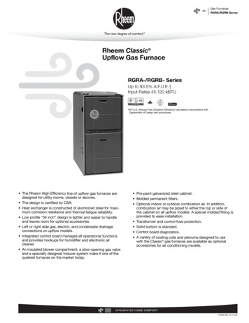
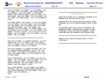
Unit DimensionsNOTE -C*20 size units installed in upflow applications thatrequire air volumes of 1800 cfm (850 L/s or greater musthave one of the following:11.2.3.4.5.25 (635)DSingle side return air with transition, to accommodate 20x 25 x 1 in. (508 x 635 x 25 mm) air filter.Single side return air with optional RAB Return Air BaseBottom return air.Return air from both sides.Bottom and one side return air.TopViewFlue outlet may be horizontal but furnace must be ventedvertically.2Optional external side return air filter kit cannot be used withthe optional RAB Return Air Base.328-3/8 (721)Right SideView* Consider sizing requirements for optional IAQ equipment beforecutting side return opening.19-1/2 23(584)3-1/4(83)33(838)BottomViewC23-1/2(597)Front 4958203Page 2 of 33Issue 1809507330-01B
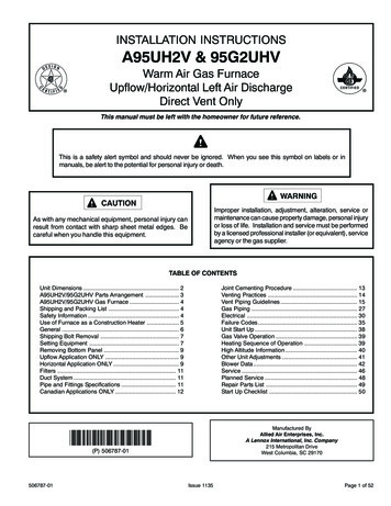
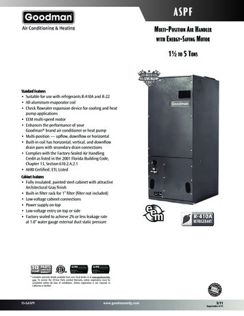
ClearancesBG801UHE Gas FurnaceThe BG801UHE gas furnace is shipped ready forinstallation in the upflow or horizontal right position (forhorizontal left position the combustion air pressure switchmust be moved). The furnace is shipped with the bottompanel in place. The bottom panel must be removed if theunit is to be installed in horizontal or upflow applicationswith bottom return air.Adequate clearance must be made around the air openingsinto the vestibule area. In order to ensure proper unitoperation, combustion and ventilation air supply must beprovided according to the current National Fuel Gas Code.Vent installations must be consistent with the ventingtables (in this instruction) and applicable provisions of localbuilding codes.The furnace is equipped for installation in natural gasapplications. A conversion kit (ordered separately) isrequired for use in propane/LP gas applications.This furnace is CSA International certified for installationclearances to combustible material as listed on the unitnameplate and in the tables in Figure 7 and Figure 11.Accessibility and service clearances must take precedenceover fire protection clearances.Shipping and Packing ListInstalled LocationsFor installation in a residential garage, the furnace must beinstalled so that the burner(s) and the ignition source arelocated no less than 18 inches (457 mm) above the floor.The furnace must be located or protected to avoid physicaldamage by vehicles. When a furnace is installed in a publicgarage, hangar, or other building that has a hazardousatmosphere, the furnace must be installed according torecommended good practice requirements and currentNational Fuel Gas Code.1 - Assembled Gas Furnace1 - Bag assembly containing the following:2 - Screws3 - Wire nuts1 - Snap bushing1 - Snap Plug1 - Wire tieTemperature Rise1 - Vent warning label1 - Owner’s manual and warranty cardCheck equipment for shipping damage. If you find anydamage, immediately contact the last carrier.Please NOTE: Furnace must be adjusted to obtain a temperaturerise within the range specified on the unit nameplate.Failure to do so may cause erratic limit operation and mayresult in premature heat exchanger failure.This furnace must be installed so that its electricalcomponents are protected from water.Installed in Combination with a Cooling CoilSafety InformationDANGERDANGER OF EXPLOSION!There are circumstances in which odorant used withLP/Propane gas can lose its scent. In case of a leak,LP/Propane gas will settle close to the floor and may bedifficult to smell. An LP/Propane leak detector should beinstalled in all LP applications.When this furnace is used with cooling units, it shall beinstalled in parallel with, or on the upstream side of, coolingunits to avoid condensation in the heating compartment.See Figure 1. With a parallel flow arrangement, a damper(or other means to control the flow of air) must adequatelypre vent chilled air from entering the furnace. If the damperis manually operated, it must be equipped to preventoperation of either the heating or the cooling unit, unless itis in the full HEAT or COOL setting. See Figure 1.CertificationsThese units are CSA International certified to ANSI Z21.47.In the USA, installation of gas furnaces must conform withlocal building codes. In the absence of local codes, unitsmust be installed according to the current National FuelGas Code (ANSI-Z223.1). The National Fuel Gas Code isavailable from the following address: American NationalStandards Institute, Inc., 11 West 42nd Street, New York,NY 10036.507330-01BIssue 1809Page 3 of 33
Heating Unit Installed Parallel to Air Handler UnitHeating Unit Installed Upstream of Cooling UnitFigure 1.When installed, this furnace must be electrically groundedaccording to local codes. In addition, in the United States,installation must conform with the current NationalElectric Code, ANSI/NFPA No. 70. The National ElectricCode (ANSI/NFPA No. 70) is available from the followingaddress:National Fire Protection Association1 Battery March ParkQuincy, MA 02269NOTE: This furnace is designed for a minimum continuousreturn air temperature of 60 F (16 C) or an intermittentoperation down to 55 F (13 C) dry bulb for cases wherea night setback thermostat is used. Return air temperaturemust not exceed 85 F (29 C) dry bulb.This furnace may be installed in alcoves, closets, attics,basements, garages, and utility rooms in the upflow orhorizontal position.This furnace design has not been CSA certified forinstallation in mobile homes, recreational vehicles, oroutdoors.Use of Furnace as a Construction HeaterUnits may be used for heating of buildings or structuresunder construction, if the following conditions are met toensure proper operation.DO NOT USE THE UNIT FOR CONSTRUCTION HEATUNLESS ALL OF THE FOLLOWING CRITERIA AREMET:a.Furnace must be in its final location. The vent systemmust be permanently installed per these installationinstructions.Page 4 of 33b.Furnace must be installed as a two pipe systemand one hundred percent (100%) outdoor air mustbe provided for combustion air requirements duringconstruction.c.A room thermostat must control the furnace. The useof fixed jumpers that will provide continuous heating isprohibited.d.The input rate and temperature rise must be set perthe furnace rating plate.e.Supply and Return air ducts must be provided andsealed to the furnace. Return air must be terminatedoutside of the space where furnace is installed.f.Return air temperature range between 60 F (16 C)and 80 F (27 C) must be maintained.g.MERV 11 or greater air filters must be installed inthe system and must be regularly inspected andmaintained (e.g., regular static checks and replaced atend of life) during construction.h.Blower and vestibule access panels must be in placeon the furnace at all times.i.The furnace heat exchanger, components, ductsystem, and evaporator coils must be thoroughlycleaned following final construction clean up.j.Air filters must be replaced upon constructioncompletion.k.All furnace operating conditions (including ignition,input rate, temperature rise and venting) mustbe verified in accordance with these MATURECOMPONENT FAILURE AS A RESULT OF FAILURE TOFOLLOW THE ABOVE INSTALLATION INSTRUCTIONS.FAILURE TO FOLLOW THE ABOVE INSTALLATIONINSTRUCTIONS VOIDS THE MANUFACTURER’SEQUIPMENT LIMITED WARRANTY. BLUE SUMMITDISCLAIMS ALL LIABILITY IN CONNECTION WITHINSTALLER’S FAILURE TO FOLLOW THE ABOVEINSTALLATION INSTRUCTIONS.NOTWITHSTANDING THE FOREGOING, INSTALLERIS RESPONSIBLE FOR CONFIRMING THAT THE USEOF CONSTRUCTION HEAT IS CONSISTENT WITHTHE POLICIES AND CODES OF ALL REGULATINGENTITIES. ALL SUCH POLICIES AND CODES MUST BEADHERED TO.GeneralThese instructions are intended as a general guide and donot supersede local codes in any way. Consult authoritieshaving jurisdiction before installation.Issue 1809507330-01B
In addition to the requirements outlined previously, thefollowing general recommendations must be consideredwhen installing one of these furnaces: Place the furnace as close to the center of the airdistribution system as possible. The furnace shouldalso be located close to the chimney or vent terminationpoint. Do not install the furnace where drafts might blowdirectly into it. This could cause improper combustion. Do not block the furnace combustion air openings withclothing, boxes, doors, etc. Air is needed for propercombustion and safe unit operation. When the furnace is installed in an attic or otherinsulated space, keep insulation away from thefurnace.All gas fired appliances require air for the combustionprocess. If sufficient combustion air is not available, thefurnace or other appliances will operate inefficientlyand unsafely. Enough air must be provided to meet theneeds of all fuel burning appliances and appliances suchas exhaust fans which force air out of the house. Whenfireplaces, exhaust fans, or clothes dryers are used at thesame time as the furnace, much more air is necessary toensure proper combustion and to prevent a downdraft.Insufficient air causes incomplete combustion which canresult in carbon monoxide.WARNINGInsufficient combustion air can cause headaches,nausea, dizziness or asphyxiation. It will also causeexcess water in the heat exchanger resulting in rustingand premature heat exchanger failure. Excessiveexposure to contaminated combustion air will resultin safety and performance related problems. Avoidexposure to the following substances in the combustionair supply:NOTE: The Commonwealth of Massachusetts stipulatesthese additional requirements: Gas furnaces shall be installed by a licensed plumberor fitter only. The gas cock must be “T handle” type. When a furnace is installed in an attic, the passagewayto and service area surrounding the equipment shallbe floored.Combustion, Dilution & Ventilation AirIn the past, there was no problem in bringing in sufficientoutdoor air for combustion. Infiltration provided all the airthat was needed. In today’s homes, tight constructionpractices make it necessary to bring in air from outsidefor combustion. Take into account that exhaust fans,appliance vents, chimneys, and fireplaces force additionalair that could be used for combustion out of the house.Unless outside air is brought into the house for combustion,negative pressure (outside pressure is greater than insidepressure) will build to the point that a downdraft can occurin the furnace vent pipe or chimney. As a result, combustiongases enter the living space creating a potentiallydangerous situation. Permanent wave solutions Chlorinated waxes and cleaners Chlorine base swimming pool chemicals Water softening chemicals De-icing salts or chemicals Carbon tetrachloride Halogen type refrigerants Cleaning solvents (such as perchloroethylene) Printing inks, paint removers, varnishes, etc. Hydrochloric acid Antistatic fabric softeners for clothes dryers Masonry acid washing materialsIn addition to providing combustion air, fresh outdoor airdilutes contaminants in the indoor air. These contaminantsmay include bleaches, adhesives, detergents, solventsand other contaminants which can corrode furnacecomponents.In the absence of local codes concerning air for combustionand ventilation, use the guidelines and procedures in thissection to install these furnaces to ensure efficient andsafe operation. You must consider combustion air needsand requirements for exhaust vents and gas piping.The requirements for providing air for combustion andventilation depend largely on whether the furnace isinstalled in an unconfined or a confined space.A portion of this information has been reprintedwith permission from the National Fuel Gas Code(ANSI-Z223.1). This reprinted material is not the completeand official position of the ANSI on the referenced subject,which is represented only by the standard in its entirety.An unconfined space is an area such as a basementor large equipment room with a volume greater than 50cubic feet (1.42 m3) per 1,000 Btu (.29 kW) per hour ofthe combined input rating of all appliances installed in thatspace. This space also includes adjacent rooms which arenot separated by a door. Though an area may appear tobe unconfined, it might be necessary to bring in outdoor air507330-01BUnconfined SpaceIssue 1809Page 5 of 33
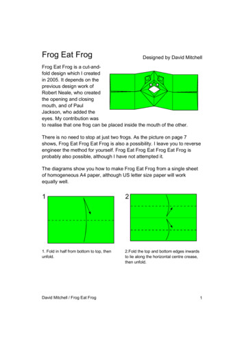
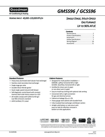
for combustion if the structure does not provide enough airby infiltration. If the furnace is located in a building of tightconstruction with weather stripping and caulking aroundthe windows and doors, follow the procedures in the airfrom outside section.Confined SpaceA confined space is an area with a volume less than 50cubic feet (1.42 m3) per 1,000 Btu (.29 kW) per hour ofthe combined input rating of all appliances installed in thatspace. This definition includes furnace closets or smallequipment rooms.When the furnace is installed so that supply ducts carryair circulated by the furnace to areas outside the spacecontaining the furnace, the return air must be handled byducts which are sealed to the furnace casing and whichterminate outside the space containing the furnace. Thisis especially important when the furnace is mounted ona platform in a confined space such as a closet or smallequipment room. Even a small leak around the base of theunit at the platform or at the return air duct connection cancause a potentially dangerous negative pressure condition.Air for combustion and ventilation can be brought into theconfined space either from inside the building or fromoutside.(64516 mm2). One opening shall be within 12 inches (305mm) of the top of the enclosure and one opening within 12inches (305 mm) of the bottom. See Figure 2.Air from OutsideIf air from outside is brought in for combustion andventilation, the confined space must have two permanentopenings. One opening shall be within 12 inches (305mm) of the top of the enclosure and one opening within12 inches (305 mm) of the bottom. These openings mustcommunicate directly or by ducts with the outdoors orspaces (crawl or attic) that freely communicate with theoutdoors or indirectly through vertical ducts. Each openingshall have a minimum free area of 1 square inch (645 mm2)per 4,000 Btu (1.17 kW) per hour of total input rating of allequipment in the enclosure. See Figure 3 and Figure 4.When communicating with the outdoors through horizontalducts, each opening shall have a minimum free area of 1square inch (645 mm2) per 2,000 Btu (.56 kW) per totalinput rating of all equipment in the enclosure. See Figure 5.When ducts are used, they shall be of the same crosssectional area as the free area of the openings to whichthey connect. The minimum dimension of rectangularair ducts shall be no less than 3 inches (75 mm). Incalculating free area, the blocking effect of louvers, grilles,or screens must be considered. If the design and free areaof protective covering is not known for calculating the sizeopening required, it may be assumed that wood louverswill have 20 to 25 percent free area and metal louvers andgrilles will have 60 to 75 percent free area. Louvers andgrilles must be fixed in the open position or interlockedwith the equipment so that they are opened automaticallyduring equipment operation.NOTE: Each opening shall have a free area of at least one squareinch per 1,000 Btu (645 mm² per .29 kW) per hour of the totalinput rating of all equipment in the enclosure, but not less than 100square inches (64546 mm²).Figure 2. Equipment in Confined Space - All Air FromInsideAir from InsideIf the confined space that houses the furnace adjoins aspace categorized as unconfined, air can be brought inby providing two permanent openings between the twospaces. Each opening must have a minimum free area of 1square inch (645 mm2) per 1,000 Btu (.29 kW) per hour oftotal input rating of all gas fired equipment in the confinedspace. Each opening must be at least 100 square inchesPage 6 of 33NOTE: The inlet and outlet air openings shall each have a freearea of at least one square inch per 4,000 Btu (645 mm² per1.17 kW) per hour of the total input rating of all equipment in theenclosure.Figure 3. Equipment in Confined Space - All Air fromOutside(Inlet Air from Crawl Space & Outlet Air to VentilatedAttic)Issue 1809507330-01B
Setting EquipmentWARNINGDo not install the furnace on its front or its back. Do notconnect the return air ducts to the back of the furnace.Doing so will adversely affect the operation of the safetycontrol devices, which could result in personal injury ordeath.The gas furnace can be installed as shipped in either theupflow position or the horizontal position.Select a location that allows for the required clearancesthat are listed on the unit nameplate. Also consider gassupply connections, electrical supply, vent connection, andinstallation and service clearances [24 inches (610 mm) atunit front]. The unit must be level.NOTE: The inlet and outlet air openings shall each have a freearea of at least one square inch per 4,000 Btu (645 mm² per1.17 kW) per hour of the total input rating of all equipment in theenclosure.Figure 4. Equipment in Confined Space - All Air fromOutside(All Air through Ventilated Attic)NOTE: Units with 1/2 hp and 3/4 hp blower motors areequipped with three flexible legs and one rigid leg. SeeFigure 6. The rigid leg is equipped with a shipping bolt anda flat white plastic washer (rather than the rubber mountinggrommet used with a flexible mounting leg). The bolt andwasher must be removed before the furnace is placed intooperation. After the bolt and washer have been removed,the rigid leg will not touch the blower housing.Units with 1/2 HP & 3/4 HPBlower Motor.NOTE: Each air duct opening shall have a free area of at least onesquare inch per 2,000 Btu (645 mm² per .59 kW) per hour of thetotal input rating of all equipment in the enclosure. If the equipmentroom is located against an outside wall and the air openingscommunicate directly with the outdoors, each opening shall havea free area of at least 1 square inch per 4,000 Btu (645 mm² per1.17 kW) per hour of the total input rating of all other equipment inthe enclosure.Figure 6.Figure 5. Equipment in Confined Space - All Air fromOutside507330-01BIssue 1809Page 7 of 33
Upflow ApplicationsAllow for clearances to combustible materials as indicatedon the unit nameplate. Minimum clearances for closet oralcove installations are shown in Figure 7.Type of VentConnectorType CType B1Top1 in. (25 mm)1 in. (25 mm)*Front2-1/4 in. (57 mm)2-1/4 in. (57 mm)Back00Sides0†0Vent6 in. (152 mm)1 in. (25 mm)Floor0‡0‡2.Single side return air with optional return airbase. SeeFigure 12.3.Bottom return air.4.Return air from both sides.5.Bottom and one side return air.Figure 8. Single Side Return Air(with transition and filter)Removing the Bottom PanelRemove the two screws that secure the bottom cap to thefurnace. Pivot the bottom cap down to release the bottompanel. Once the bottom panel has been removed, reinstallthe bottom cap. See Figure 9.* Front clearance in alcove installation must be 24 in. (610mm). Maintain a minimum of 24 in. (610 mm) for front serviceaccess.‡ For installation on a combustible floor, do not install thefurnace directly on carpeting, tile or other combustiblematerials other than wood flooring.† Left side requires 3 in. if a single wall vent is used on 14-1/2in. cabinets.Figure 7. Upflow Application Installation ClearancesReturn Air - Upflow ApplicationsReturn air can be brought in through the bottom or eitherside of the furnace installed in an upflow application. If thefurnace is installed on a platform with bottom return, makean airtight seal between the bottom of the furnace and theplatform to ensure that the furnace operates properly andsafely. The furnace is equipped with a removable bottompanel to facilitate installation.Markings are provided on both sides of the furnace cabinetfor installations that require side return air. Cut the furnacecabinet at the maximum dimensions shown on Page 2.NOTE: 20C and 20D units that require air volumes over1800 cfm (850 L/s) must have one of the following:1.Single side return air with transition to accommodate20 x 25 x 1 in. (508 x 635 x 25 mm) cleanable air filter.(Required to maintain proper air velocity.) See Figure8.Page 8 of 33Figure 9. Removing the Bottom PanelHorizontal ApplicationsThe furnace can be installed in horizontal applications.Order horizontal suspension kit (51W10) from BlueSummit, or use equivalent suspension method.Allow for clearances to combustible materials as indicatedon the unit nameplate. Minimum clearances for closet oralcove installations are shown in Figure 11.Issue 1809507330-01B
This furnace may be installed in either an attic or a crawlspace. Either suspend the furnace from roof rafters or floorjoists, as shown in Figure 10, or install the furnace on aplatform, as shown in Figure 13.Type of VentConnectorType CType B1Top00*Front2-1/4 in. (57 mm)2-1/4 in. (57 mm)Back00Ends2 in. (51 mm)2 in. (51 mm)Vent6 in. (152 mm)1 in. (25 mm)Floor0‡0‡* Front clearance in alcove installation must be 24 in. (610mm). Maintain a minimum of 24 in. (610 mm) for front serviceaccess.Figure 10. Typical Horizontal ApplicationUnit Suspended in Attic or Crawl Space‡ For installation on a combustible floor, do not install thefurnace directly on carpeting, tile or other combustiblematerials other than wood flooring.Figure 11. Horizontal Application InstallationClearancesFURNACEFRONTINDOOR AIRQUALITYCABINETAIR FLOW14-1/2 (368) A Width (65W75)17-1/2 (446) B Width (68W62)21 (533) C Width (68W63)24-1/2 (622) D Width (68W64)IF BASEIS USEDWITHOUTIAQ CABINET,A SINGLERETURN AIRPLENUMMUSTCOVER BOTHUNIT ANDRETURNAIR BASEOPENINGS3 1/4(83)7 1/4(184)1 23(584)Overall(Maximum)1Minimum11 (279)2 Maximum1 Unit side return air14 (356)Opening5 5/8(143)FRONT VIEW(570)Overall(Maximum)SIDE RETURNAIR OPENINGS(Either Side)23(584)26 7/8(683)OPTIONALRETURNAIR BASE1 22 7/163/4(19)SIDE VIEWNOTE: Optional Side Return Air Filter Kits are not for use with Return Air Base.1Both the unit return air opening and the base return air opening must be covered by a single plenum or IAQ cabinet.Minimum unit side return air opening dimensions for units requiring 1800 cfm or more of air (W x H): 23 x 11 in. (584 x 279 mm).The opening can be cut as needed to accommodate plenum or IAQ cabinet while maintaining dimensions shown.Side return air openings must be cut in the field. There are cutting guides stenciled on the cabinet for the side return air opening.The size of the opening must not extend beyond the markings on the furnace cabinet.² To minimize pressure drop, the largest opening height possible (up to 14 inches) is preferred.Figure 12. Optional Return Air Base(Upflow Applications Only - For Use with A, B, C and D Cabinets)507330-01BIssue 1809Page 9 of 33
NOTE: Heavy gauge perforated sheet metal straps maybe used to suspend the unit from roof rafters or ceilingjoists. When straps are used to suspend the unit in thisway, support must be provided for both the ends. Thestraps must not interfere with the plenum or exhaustpiping installation. Cooling coils and supply and return airplenums must be supported separately.NOTE: When the furnace is installed on a platform in acrawlspace, it must be elevated enough to avoid waterdamage and to allow the evaporator coil to drain.Return Air - Horizontal ApplicationsReturn air must be brought in through the end of a furnaceinstalled in a horizontal application. The furnace is equippedwith a removable bottom panel to facilitate installation. SeeFigure 9.WARNINGThe inner blower panel must be securely in place whenthe blower and burners are operating. Gas fumes,which could contain carbon monoxide, can be drawninto living space resulting in personal injury or death.FiltersThis unit is not equipped with a filter or rack. A field providedhigh velocity filter is required for the unit to operate properly.Table 1 lists recommended filter sizes.A filter must be in place any time the unit is operating.Furnace CabinetWidthB - 17-1/2”C - 21”Filter SizeSide Return16 x 25 x 1Bottom Return16 x 25 x 120 x 25 x 1Table 1.Duct SystemFigure 13. Horizontal ApplicationUnit Installed on PlatformWARNINGImproper installation of the furnace can result inpersonal injury or death. Combustion and flue productsmust never be allowed to enter the return air system orthe living space. Use screws and joint tape to seal thereturn air system to the furnace.In platform installations with bottom return air, the furnaceshould be sealed airtight to the return air plenum. A doormust never be used as a portion of the return air ductsystem. The base must provide a stable support and anairtight seal to the furnace. Allow absolutely no sagging,cracks, gaps, etc.The return and supply air duct systems must neverbe connected to or from other heating devices suchas a fireplace or stove, etc. Fire, explosion, carbonmonoxide poisoning, personal injury and/or propertydamage could result.Page 10 of 33Use industry approved standards (such as those publishedby Air Conditioning Contractors of America or AmericanSociety of Heating, Refrigerating and Air ConditioningEngineers) to size and install the supply and return air ductsystem. This will result in a quiet and low static system thathas uniform air distribution.NOTE: Do not operate the furnace in the heating modewith an external static pressure that exceeds 0.8 inchesw.c. Higher external static pressures may cause erraticlimit operation.Supply Air PlenumIf the furnace is installed without a cooling coil, a removableaccess panel must be installed in the supply air duct. Theaccess panel should be large enough to permit inspection(either by smoke or reflected light) of the heat exchangerfor leaks after the furnace is installed. The furnace accesspanel must always be in place when the furnace is operatingand it must not allow leaks into the supply air duct system.Return Air PlenumNOTE: Return air must not be drawn from a room wherethis furnace, or any other gas fueled appliance (i.e., waterheater), or carbon monoxide producing device (i.e., woodfireplace) is installed.Issue 1809507330-01B
When return air is drawn from a room, a negative pressureis created in the room. If a gas appliance is operating ina room with negative pressure, the flue products can bepulled back down the vent pipe and into the room. Thisreverse flow of the flue gas may result in incompletecombustion and the formation of carbon monoxide gas.This toxic gas might then be distributed throughout thehouse by the furnace duct system.The unit will not vent properly with the flue transitionpointed down in the 6 o’clock position.In upflow applications, the return air can be broughtin through the bottom or either side of the furnace. If afurnace with bottom return air is installed on a platform,make an airtight seal between the bottom of the furnaceand the platform to ensure that the unit operates properlyand safely. Use fiberglass sealing strips, caulking, orequivalent sealing method between the plenum and thefurnace cabinet to ensure a tight seal. If a filter is installed,size the return air duct to fit the filter frame.If necessary reposition the combustion air inducer,pressure switch and/or make-up box as needed per thefollowing steps. See Figure 15 through Figure 21.IMPORTANTThe combustion air inducer may be rotated clockwiseor counterclockwise by 90 to allow for top or side ventdischarge in all applications. When the unit is installed,the flue transition must be in the 9 o’clock, 12 o’clock or3 o’clock position.1.Remove the four mounting screws (Figure 14) whichsecure the combustion air inducer / pressure switchassembly to the orifice plate. Lift the assembly androtate it 90 clockwise or counter clockwise to eitherthe 3 o’clock position. Resecure with four screws.Gasket should be left in pl
B 33 (838) A 1 NOTE-C*20 size units installed in upflow applications that require air volumes of 1800 cfm (850 L/s or greater must have one of the following: 1. Single side return air with transition, to accommodate 20 x 25 x 1 in. (508 x 635 x 25 mm) air filter. 2. Single side return air with optional RAB Return Air Base 3. Bottom return air. 4.