Transcription
UVL-COIL Ultraviolet Lamp Kitsfor AHU CoilsPRODUCT DATAFEATURES UV-C light irradiates coil & air handler interior, killingmold, bacteria and viruses Scalable design allows wide variety of multi-lampconfigurations High quality water-resistant lamps Mounts using off-the-shelf ½ inch EMT conduittubing Includes 10 foot cable & all mounting hardwareexcept ½ inch EMT conduit Saves energy by keeping components cleanerAPPLICATIONThe system is designed for installation into commercial airhandling units for the purpose of surface disinfectionusing ultraviolet germicidal irradiation. For maximuminstallation flexibility and cost-effectiveness, the UVlamps are mounted onto a framework of standard ½ inchEMT tubing (not included). The remotely mounted weatherresistant power supply can withstand the wet environmentfound inside of air handlers or the exposed conditions ofoutdoor packaged air conditioning systems. The numberand placement of lamps is determined by the coildimensions.ContentsAPPLICATION .FEATURES .SPECIFICATIONS .PLANNING THE INSTALLATION .ORDERING INFORMATION .INSTALLATION .WIRING .MAINTENANCE .TROUBLESHOOTING .11232566731-00402-02
UVL-COIL ULTRAVIOLET LAMP KITS FOR AHU COILSSPECIFICATIONSBulb:UVL-32-LAMP: 33.75 in (857 mm) lengthUVL-60-LAMP: 61.25 in (1156 mm) lengthModels: See Table 1.UV-C Power:UVL-32-LAMP: 28 WUVL-60-LAMP: 54 WEfficiencies: 99.9% disinfection of irradiated surfaceswhen properly positionedApprovals: ETL/CSA, RoHS standard 2011/65/EU, WEEE,EPA Est. No. 075179-FL-2Output at 1 Meter:UVL-32-LAMP: 250 μW/cm2UVL-60-LAMP: 395 μW/cm2Electrical Ratings:Power Rating: 120-277 Vac, 50/60 HzCurrent Rating: 2 A except dual 60 inch, 3 ASpectrum:100% 254 nm Germicidal UV-CTemperature Ratings:Lamp Temperature Range: 35 to 185 F (1.7 to 85 C)Bulb Type:Shielded Quartz Hot FilamentDimensions:Power Supply: 13.0 in x 3.75 in x 2.5 in(330 mm x 95.3 mm x 63.5 mm)Bulb Life:18,000 hoursAccessories:UVL-32-LAMP 32 inch replacement lampUVL-60-LAMP 60 inch replacement lampTable 1. Models.Part NumberDescriptionReplacement Lamp(s)Power Supply*UVL-COIL-32SRTU / AHU 32" Single BulbUVL-32-LAMP(MFR# TUVCL-232HO)(MFG# TUVCPS-HS)UVL-COIL-32DRTU / AHU 32" Double BulbUVL-32-LAMP (2)(MFR# TUVCL-232HO)(MFG# TUVCPS-H32D)UVL-COIL-60SRTU / AHU 60" Single BulbUVL-60-LAMP(MFR# TUVCL-260HO)(MFG# TUVCPS-HS)UVL-COIL-60DRTU / AHU 60" Double BulbUVL-60-LAMP (2)(MFR# TUVCL-260HO)(MFG# TUVCPS-H46-60D)*Power supply not available for purchase outside of kit.31-00402—022
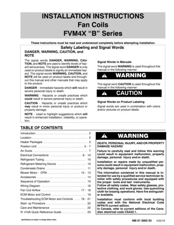
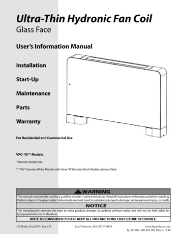
UVL-COIL ULTRAVIOLET LAMP KITS FOR AHU COILSPLANNING THEINSTALLATIONADBHJLWARNINGWARNINGEOnly qualified technicians should install thisproduct.Install in accordance with relevant building codes.Read instructions carefully including safetywarnings.CIFKGParts IncludedA. UV Lamp(s) 2 YearB. Lamp CableC. Power Supply(s)D. Sheet-metal ScrewsE. 1/2” Pipe StrapsFig. 1. PartsF. 1/2” Pipe CouplingsSystem ConfigurationG. Lamp Clip/Conduit ClampsDetermine the dimensions of the coil to be irradiated. UseTable 2 To determine which kit is needed based on the coilsize. Table 3 can be used to estimate the kits needed basedon the tonnage of the unit. The coil size should be verifiedto insure proper fit.H. L - Mounting BracketsI. Black Nylon Zip-TiesJ. UV Warning StickerBefore attaching the L-brackets for mounting use optimalirradiation distance (Fig. 2.) and lamp spacing (Fig. 3.)diagrams to confirm than when installed the UV lamps willbe positioned properly. The UV lamps are mounted onto aframework of EMT tubing. When two or more UV lamps aresupported on a single length of EMT it is recommended toadd an optional vertical support. (Fig. 4.)K. Sight GlassL. ½” EMT Electrical Conduit (not included, several lengthsrequired depending on configuration)Table 2. Sizing Based on Coil Dimensions.Coil Height (inches)Coil Width 0DUVL-COIL-60DTable 3. Sizing Based on Unit Tonnage.Tonnage6-10 Ton10-15 Ton15-30 Ton20-30 Ton30-40 DUVL-COIL-60D331-00402—02
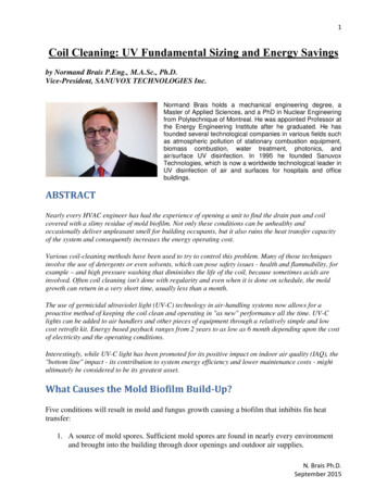
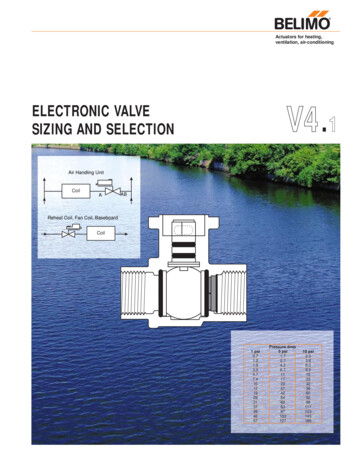
UVL-COIL ULTRAVIOLET LAMP KITS FOR AHU COILSCoil12” Lamp to Coil36”Max36” Lamp toLampMaxMultiple lamps with Optional Vertical Support to prevent saggingFig. 4. Vertical Support Configuration.UV Lamp Configuration Guidelines Maximum germicidal effectiveness is within an 18 inchradius from UV lamp center axis. The optimal distance between UV lamp(s) and theirradiated surface is 12 inch. The distance between stacked UV lamps should notexceed 36 inches. The distance between end to end UV lamps should notexceed 12 inches. The distance of UV lamp ends to the edge of irradiatedsurface should not exceed 10 inches. The spacing guidelines above may not apply for allapplications. Use recommendations in Table 2 to selectappropriate kit based on coil size.Fig. 2. Optimal Irradiation Distance.12” Max. space between lamps10” Max. space to end of coilsWARNINGOverlap lamps where necessaryBe careful of damage to equipment.Ultraviolet light can cause color fading or degradedstructure of plastic material found in HVACequipment, avoid plastic material or equipmentwith unknown performance against ultraviolet lightin the area of irradiation.Fig. 3. Lamp Spacing.WARNINGUV Light Hazard.Harmful to bare skin and eyes.Can cause temporary or permanent loss of vision.Do not look at the UV lamp when lighting is on. Useindicator light on the ballast to check status. Inorder to prevent exposure to UV light, before repairof any parts of HVAC system, shut off power supplyto UV system. Do not install in a position where UVlamp is visible during normal operation of HVACequipment.31-00402—024
UVL-COIL ULTRAVIOLET LAMP KITS FOR AHU COILSINSTALLATIONtubing length. Measure the distance from floor toceiling then measure and cut tubing 1.75 inches lessthan that length. Use ½ inch pipe coupling to extendthe vertical support to the floor and ceiling for a snugfit. (Fig. 7.)When Installing This Product 1.2.3.4.Read these instructions carefully. Failure to followthem could damage the product or cause a hazardous condition.Check the ratings given in the instructions and on theproduct to make sure the product is suitable for yourapplication.Installer must be a trained, experienced service technician.After installation is complete, check out productoperation as provided in these instructions.1/2” Pipe CouplingWARNINGConduit/conduitClampElectric Shock Hazard.Can cause electrical shock or equipment damage.Do not connect to power before installation iscomplete.Assemble Conduit Framework1.Vertical SupportMeasure and cut tubing to length then slide on conduit/lamp clamps (Fig. 5.), do not fully tighten boltsyet.1/2” Pipe CouplingFig. 7. Optional Vertical Support.Install UV LampsFig. 5. Slide on Hardware.2.Snap UV Lamps into the lamp/conduit clamps. Be sure toclamp to the rubber lamp connector on one end and theceramic lamp tip on the other end. DO NOT clamp onto thelamp glass. Use black nylon zip-ties to secure lamp cablesto tubular rack components and/or supports.Use self-tapping screws to attach L-brackets to theair handler wall or supporting structure. Then use the½ inch pip clamps to attach the tubing sections tothe L-Brackets. (Fig. 6.)CAUTIONBreakable Glass Hazard.Can cause personal injury.Be careful when inserting bulb(s) into lamp base.Wear protective gloves when handling bulb(s).MERCURY NOTICEConduitThis device contains mercury in the sealedultraviolet bulb(s). Do not place your used bulb(s) inthe trash. Dispose of properly.Broken Bulb CleanupDo not use a household vacuum. Sweep debris into aplastic bag and dispose of properly.Fig. 6. Mount L-bracket and Tubing.3.Contact your local waste management authority forinstructions regarding recycling and the proper disposal ofold bulb(s).An optional vertical support adds strength to theconduit tubing to support framework and preventssagging on installations with three or more lamps per531-00402—02
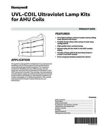
UVL-COIL ULTRAVIOLET LAMP KITS FOR AHU COILSUV LAMPUV LAMPCONNECTORSL1 BLACKUV LampL2 or N WHITEGND GREENFig. 8. Installing UV Lamp.120-277 VACPOWER SUPPLYFig. 10. Electrical Connections.Mount Power Supply(s)Mount the power supply in a location (inside or outside ofthe HVAC system) that is convenient for access to the mainpower supply and for connection to the UV lamps. Thepower supply is weather resistant and is suitable formounting inside or outside of the air handler.Connect Lamps and CablesArrange cables as needed for installation. If necessary, usecable strain relief fittings or other means to pass cablesthrough the cabinets or air system walls. When UV lamps,power supplies, and cables are in place join the lamp andpower supply cables by aligning the electrical pins andflanges on the rubber connectors and pushing them firmlytogether.Use the supplied self-taping sheet metal screws to mountthe power supply in place through the mounting holes onthe sides of the base. It is recommended to use wire boxes,cable strain relief fittings, or other sealing methods in orderto pass the power cord and lamp cables into the interior ofthe air handler for connections.Align Pins & Lamp KeySight Glass InstallationLamp KeyThe sight glass allows safe viewing of the UV light systemwhen in operation. Find a suitable location such as a doorto the HVAC system for the sight glass. Drill a 1” hole andpress the base of the sight glass through it.V LampUVPush Firmly TogetherPower SupplyCableFig. 11. Align Pins and Lamp Key.MAINTENANCEFig. 9. Sight Glass Installation.Honeywell UVC lights are made of Hard Quartz. Unlike SoftQuartz, these lamps do NOT need to be wiped of grease orother contaminants, and are NOT affected by humidity.They are warranted for 2 years of UVC output, to 60% oftheir original output. Sizing guidelines are based on theend of lamp life output levels.WIRINGWARNINGElectric Shock Hazard.Can cause personal injury.Turn off main power before making electricalconnections.Honeywell UV lamps are rated for two years germicidaleffectiveness. The visible blue light will continue toilluminate, but does NOT have any germicidaleffectiveness. Bulbs must be replaced on schedule for thesystem to function properly.Refer to electrical diagram (Fig. 10.) for proper connectionsof the power supply to the main power.31-00402—02IMPORTANTUse only Honeywell replacement lamps. Use ofreplacement lamps from other manufacturersvoids the warranty. See Table 1 for replacementlamp part numbers.6
UVL-COIL ULTRAVIOLET LAMP KITS FOR AHU COILSTROUBLESHOOTINGTable 4. Troubleshooting.ProblemSolutionUV Lamp(s) Not Lighting1.2.3.4.5.6.7.Check that power is applied.Check that the unit is turned ON.Ensure the remote lamp cables are properly connected.Check the fuse. Replace only with same size and type.Reset power switch on power supply (off then on).Install New UV Lamp(s).Consult Factory.UV Lamp(s) Flickering1. UV Lamp(s) have reached end of effective service life. Install newlamp(s) of same type.2. If unit is new, check remote cables to ensure they are properly connected.3. Reset power switch on power supply (off then on).4. If new lamps still flicker, consult factory.UV Lamps Have burned Out Prematurely1. Consult Factory.Power Supply Will Not Light UV Lamps evenafter new lamps are installed1. Consult Factory.2. External power suppressor may be needed if power surges occur.731-00402—02
UVL-COIL ULTRAVIOLET LAMP KITS FOR AHU COILSHoneywell Building TechnologiesIn the U.S.:Honeywell715 Peachtree Street NEAtlanta, GA ell.com U.S. Registered Trademark 2020 Honeywell International Inc.31-00402—02 M.S. Rev. 09-20Printed in United States
UVL-COIL Ultraviolet Lamp Kits for AHU Coils . Shielded Quartz Hot Filament Bulb Life: 18,000 hours Accessories: UVL-32-LAMP 32 inch replacement lamp . Sizing Based on Coil Dimensions. Table 3. Sizing Based on Unit Tonnage. H J L K I A D WARNING F G C B E Coil Width (inches) 32 40 48 56 62 72