Transcription
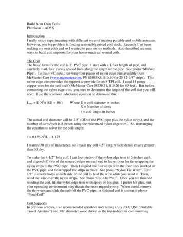
Build Your Own CoilsPhil Salas – AD5XIntroductionI really enjoy experimenting with different ways of making portable and mobile antennas.However, one big problem is finding reasonably priced coil stock. Recently I’ve beenmaking my own coils and so I wanted to pass on my methods. Also described are neatways to build coil supports for your home-made air-wound coils.The CoilThe basic form for the coil is 2” PVC pipe. I start with a 1-foot length of pipe, andcarefully mark four evenly spaced lines along the length of the pipe. See photo “MarkedPipe”. To this PVC pipe, I tie-wrap four pieces of nylon edge trim available fromMcMaster-Carr (www.mcmaster.com, PN 85085K8, 10.50 for 25 12-3/4” strips). Thisnylon edge trim provides the support to provide for an 8-TPI coil. I used 14 gaugecopper wire for the coil itself (McMaster-Carr 8873K51, 10.20 for 80-feet). But beforeconnecting the nylon edge trim, you need to determine the length of the coil that you willneed. I use the solenoid inductance equation to determine this:Luhy D2N2/(18D 40l)Where D coil diameter in inchesN Number of turnsl coil length in inchesThe actual coil diameter will be 2.5” (OD of the PVC pipe plus the nylon strips), and thenumber of turns/inch is 8 (when using the referenced nylon edge trim). So, rearrangingthe equation to solve for the coil length:l 0.156 N2/L – 1.125I wanted 30 uhy of inductance, so I made my coil 4.5” long, which should ensure greaterthan 30 uhy.To make the 4-1/2” long coil, I cut four pieces of the nylon edge trim to 5-inches each,and clipped off two of the serrated edges on each end to leave room for tie-wrapping thenylon strips to the PVC pipe. Then I aligned the four strips with the four lines marked onthe PVC pipe, and tie-wrapped the strips in place. See photo “Nylon Tie Wrap”. Drill1/8” diameter holes at each side of the coil to hold the wire while you wind it. Then,wind the wire over the nylon strips. See photo “Coil On PVC”. Once you are finishedwinding the coil, fill the nylon edge trim with epoxy or hot glue. I prefer hot glue, butyour operating environment may dictate the more rugged epoxy. When cured, removethe tie-wraps and slide the coil off the PVC pipe. A finished coil is shown in photo“Final Coil”.Coil SupportsIn previous articles, I’ve recommended sprinkler riser tubing (July 2002 QST “PortableTravel Antenna”) and 3/8” diameter wood dowel as the top-to-bottom coil mounting
insulator. My preference is to use fiberglass, but I’ve had a difficult time finding 3/8”diameter fiberglass rods locally (a good mail order web site is The Deer Shock Depot athttp://electric-deer-fence.com/). However, I’ve recently discovered ¼” diameterfiberglass bicycle flags! These give a great option if you can figure out how to use themin this application. So, I’ll show how to use both 3/8” diameter and ¼” diameter rods ascoil support insulators.Note: Use care when cutting fiberglass rods! The little fiberglass shards (the “glass” in“fiberglass”) can cause you a lot of grief. Goggles and gloves should be worn.3/8” Diameter SupportWith 3/8” diameter rods you can easily make rod interfaces using 1/8-NPT nipples andcouplings. To do this, first screw a 1/8-NPT coupling on each end of a 0.7” 1/8-NPTCLOSE nipple. Use pliers and/or wrenches to screw these on tight. Note: At this pointyou can ream out the couplers with a 3/8” drill bit if you don’t want to thread the3/8” rod (See “Reaming” photo). Be careful if you do this. I prefer threading therod as discussed below.Now unscrew the couplings. One end will brake loose, and the other will stay tight in theremaining coupling. You’ll now have a female and male end for each end of the 3/8”diameter rod. See “1/8-NPT couplings”. If you’d like, you can solder thenipple/coupling assemblies together, however the nipple/coupling assembly tends to bevery tightly secured.Next, use a 1/8-NPT die and thread the 3/8” diameter rod (wood or fiberglass) on eachend. Refer to Figure 1. Now screw the 1/8-NPT male/female coupling pairs over bothends of a 3/8” diameter wood or fiberglass rod, tightening them down snugly, but nottight enough to strip the threads. Next, drill 1/8” diameter holes completely througheach of the 1/8-NPT brass couplings and rod as shown in Figure 1. Cut two 3” lengths of1/8” diameter brass rod and insert one of these 3” sections through the holes on one brasscoupling. Center the rod so that equal lengths are available on both sides of thecoupling, and solder the rod to the coupling with a large soldering iron or Solder-it torch(be careful not to burn the wood dowel if you use a torch!).Now position the desired length of the coil such that the 3” brass rod just installed pokesthrough the last two turns on the coil. Solder the coil turns to the rod. On the oppositeend of the coil assembly, insert the remaining 3” brass rod through two adjacent turns onthis end of the coil, through the brass coupling, and through the coil turns. Solder the coilturns to the brass rod, and then solder the brass rod to the coupling.1/4” Diameter SupportFiberglass bicycle flags are readily available and inexpensive. Generally, for about 5you can purchase a 6-foot bicycle flag that will provide many coil supports. As it turnsout, ¼-inch brass compression fittings are also readily available from your local hardwarestore (I found everything I needed at ACE Hardware).
Refer to Figure 2 and the photos for details of the ¼” diameter loading coil supportsection. Use 1/4-compression-to-1/8NPT male and female brass adapters for the coilsupport end pieces. The 1/4-compression ends of the adapters do a great job of securingthe 1/4” diameter fiberglass rod as shown. After you assemble the adapters andfiberglass rod together, drill a 1/8” diameter hole completely through each of the brassadapters and fiberglass rod as shown in Figure 2.The remainder of this assembly is exactly like the 3/8” diameter coil assembly. I.e., cuttwo 3” lengths of the 1/8” diameter brass rod. Insert one of these 3” sections through theholes on one brass adapter. Center the rod so that equal lengths are available on bothsides of the adapter, and solder the rod to the coupling with a large soldering iron ortorch. Position the coil such that the 3” brass rod just installed pokes through the lasttwo turns on the coil. Solder the coil turns to the rod. On the opposite end of the coilassembly, insert the remaining 3” brass rod through two adjacent turns on this end of thecoil, through the brass coupling, and through the coil turns. Solder the coil turns to thebrass rod, and then solder the brass rod to the coupling. See the “1/4” fiberglass coilsupport” photos.ConclusionI’ve described a way for you to build low-cost high-Q air-wound inductors and coilsupports. Give it a try, and save some money on coils for your homebrew antennaprojects.3”L x 1/8”D brassrod, 2 places1/8 NPT BrassCoupling1/8NPT CLOSEnipple3/8”D wood/fiberglass1/8 NPT BrassCoupling3/8”D wood or fiberglassrod. Length as necessary.Figure 1 - Coil Support Section3/8”D wood or fiberglass rod3”L x 1/8”D brassrod, 2 places1/4”D fiberglass1/4”D fiberglass rod.¼ compression-to¼ compression-toLength as necessary.1/8NPT M OR ¼1/8NPT Fcompression-to-1/8NPTF with 1/8NPT CLOSEnippleFigure 2 - Coil Support Section1/4”D Bicycle fiberglass rod
Marked PipeNylon tie-wrapped in placeCoil on PVC and ¼” fiberglass supportFinal CoilMale & Female 1/8-NPT CouplingsNon-preferred reaming of connectors
Final coil: Female end¼” diameter fiberglass piecesFinal coil: Male end
making my own coils and so I wanted to pass on my methods. Also described are neat ways to build coil supports for your home-made air-wound coils. The Coil The basic form for the coil is 2” PVC pipe. I start with a 1-foot length of pipe, and carefully mark four evenly spaced lin