Transcription
Complete Guide to Induction Coil DesignCreating the Right Custom Inductor for Your Project
» Table ofCONTENTSSECTION 1: COIL BASICS . 4HOW COILS WORK. 4TRANSFORMER EFFECT. 5COIL BASICS. 5SECTION 2: CHOOSING YOUR COIL TYPE . 6COMMON COIL TYPES. 6COIL EFFICIENCY.11APPLICATIONS.11SECTION 3: DESIGNING YOUR COIL .12DESIGN CONSIDERATIONS.12TUBING CHOICE.12NUMBER OF COIL TURNS.14LEAD DESIGN.14BRACING OF COILS .17COUPLING DISTANCE .18COIL FORMING .19SECTION 4: CUSTOMIZING YOUR COIL DESIGN FOR HEATINGUNIFORMITY, WORKPIECE SHAPE, & PART IRREGULARITY . 20COIL CHARACTERIZATION.20SIX OTHER COMMON WAYS TO IMPROVE HEATING UNIFORMITY.21HEATING TWO SEPARATE AREAS ON A PART.22COUNTER WINDING AND SHORTED TURNS.22HEATING A PART WITH SECONDARY FABRICATIONS.23HEATING PARTS WITH TAPERED SHAPES.23HEATING A VARIETY OF DIFFERENT PARTS WITH ONE COIL.24SECTION 5: RESOURCES. 25FORMULAE & CALCULATIONS.25GLOSSARY.262Complete Guide to Induction Coil DesignISO EmblemUsing InductionContactProducts
» Complete Guide to InductionCoil DesignInduction coil design canhave a major impact on partquality, process efficiency,and manufacturing costs.This guide provides (almost)everything you need to designthe optimal coil for your partand process.The first section covers Coil Basics - essentials of how coils work(a.k.a inductors, work coils) and why they’re designed the waythey are.The second section outlines different Types of Coils, commonapplications, and what affects coil efficiency.The third section provides the details of Designing Your Coil, fromthe type of tubing to how far away your coil needs to be from yourworkpiece.The fourth section covers issues you may face regarding HeatingUniformity & Part Irregularity, plus how to address these issues.Section five includes calculations you might need and definitionsof common induction coil terminology.If you require additional assistance designing or manufacturingyour coil, don’t hesitate to contact us.3
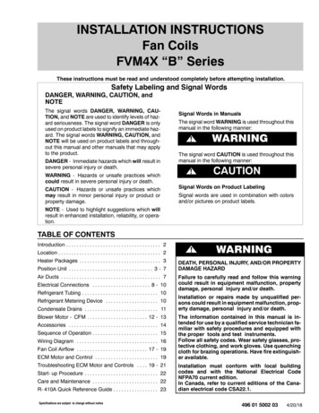
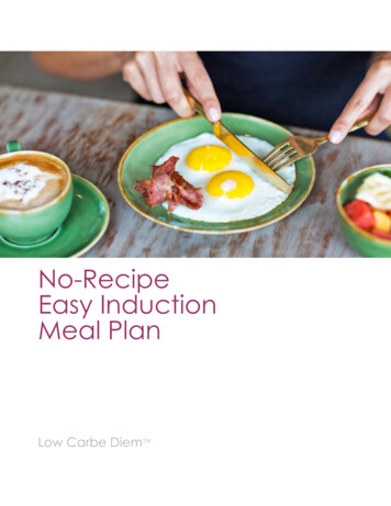
» S ection 1: Coil BasicsHOW COILS WORKThe induction coil determines how effectively and efficiently a workpiece is heated.Induction coils are water-cooled copper conductors made of copper tubing that isreadily formed into the shape of the coil for the induction heating process. Inductionheating coils do not themselves get hot as water flows through them. Work coils rangein complexity from a simple helical- or solenoid-wound coil (consisting of a number ofturns of copper tube wound around a mandrel) to a coil that is precision machined fromsolid copper and brazed.Coils transfer energy from the power supply to the workpiece by generating analternating electromagnetic field due to the alternating current flowing in them. Thecoil’s alternating electromagnetic field (EMF) generates an induced current (eddycurrent) in the workpiece, which generates heat due to I Squared R losses (core losses).The current in the workpiece is proportional to the coil’s EMF strength. This transfer ofenergy is known as the transformer effect or eddy current effect.Work Coil BasicsA current flowing in a conductor creates a magnetic field. An alternatingcurrent creates an alternating field whichproduces an alternating current in a second conductor (the work piece).The current in the work piece is proportional to the field strength.The transformer effect where the amount of current induced in the workpiece is proportional to the number of turns on the coil and is generatedas a mirror image of the work coil.4Complete Guide to Induction Coil DesignISO EmblemUsing InductionContactProducts
» S ection 1: Coil BasicsTRANSFORMERS & INDUCTIONCOILSBecause coils use the transformer effect, characteristics of transformers can be helpfulin understanding coil design. The inductor is similar to a transformer primary, and theworkpiece is equivalent to the transformer secondary (assumed to be a single turn).Two important features of transformers that impact coil design: Efficiency of coupling between the windings is inversely proportional to the square ofthe distance between them (Current in the primary of the transformer * # of primary turns) (current in thesecondary * # of secondary turns)Because of the above relationships, there are five conditions that should be kept in mindwhen designing any coil for induction heating:FIVE BASICS OF COILFUNCTIONALITY1. Higher flux density near the heating area means a higher current is generated inthe part.Coil should be coupled as close to the part as possible, and the largest possiblenumber of magnetic flux lines therefore intersect the workpiece at the heating point.This allows for maximum energy transfer.2. The greatest number of flux lines in a solenoid coil are toward the center of thecoil.The flux lines are concentrated inside the coil, providing maximum heating rate at thatlocation.3. The geometric center of the coil is a weak flux path.Flux is most concentrated closer to the coil turns themselves, and decreases withdistance from the turns.If a part were placed off center in a coil, the area closer to the coil turns wouldintersect a greater number of flux lines and thus be heated at a higher rate. The areaof the part away from the copper coil experiences less coupling and would be heatedat a lower rate.This effect is more pronounced in high-frequency induction heating.4. The magnetic center of the inductor is not necessarily the geometric center.At the point where the leads and coil join, the magnetic field is weaker.This effect is most pronounced in single-turn coils. As the number of coil turnsincreases and the flux from each turn is added to that from the previous turns, thiscondition becomes less important.Due to the impracticality of always centering the part in the work coil, the part shouldbe offset slightly toward this area in static heating applications. If possible, the partshould be rotated to provide uniform exposure.5. Coil must be designed to prevent cancellation of the magnetic field.If opposite sides of the inductor are too close, the coil does not have sufficientinductance required for efficient heating. Putting a loop in the coil at the center willoffset this effect. The coil will then heat a conducting material inserted in the opening.5
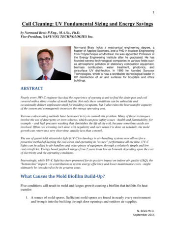
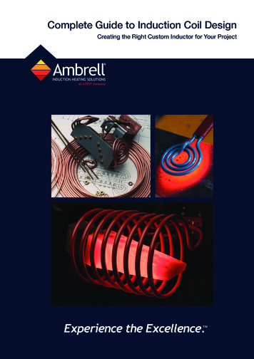
» S ection 2: Choosing Your Coil TypeTHERE ARE MORE THAN 20 DIFFERENT TYPES OF COILSUSED FOR INDUCTION HEATING.Here are their pros and cons, plus some common applications. Thehelical solenoid coil provides a wide range of heating behaviorssince the part or heating area is located within the coil, in the area ofgreatest magnetic flux.1. MULTI-TURN HELICAL COILThe helical (solenoid) is the most common and by far the most efficient coil. The numberof turns defines the length of the heating pattern.The workpiece can be stationary in the coil to provide a defined heating band in “singleshot heating.” Or, the workpiece can be moved through the coil to heat a longer part witha highly uniform heating pattern called “scan heating.2. SINGLE-TURN COILSingle-turn coils are ideal for heating a narrow band of a workpiece or the tip of aworkpiece. These coils can also scan the length of a workpiece and are commonly usedfor heat treating.These coils are often tight to the part to provide a precise heat pattern.3. MULTI-POSITION HELICAL COILMulti-position coils are often used to produce more parts in a given time while allowingfor the full heating process.Any number of positions are possible but typically up to 8 positions are practical.Parts can be heated simultaneously or can be indexed in and out of different positions,depending on the heating process required.4. CHANNEL COIL / CONVEYORSWhen power densities are low and heating cycles not extremely short, parts can beprocessed by use of a turntable or conveyor in a continuous or indexing mode. The coilmust then be designed to permit easy entry and exit of the part.Coils can be formed so the workpiece is heated as it moves through the electromagneticfield by a linear transport mechanism. The coil can be configured to heat all of the part orjust a single narrow band on the part.As long as the conveyor material is not electrically conductive, the magnetic field willpass through the conveyor and heat the workpiece as it passes through this field.The simplest conveyor or channel coil used in these situations is a modification of thehairpin inductor. With the indexing technique, in which the part is at rest in the coilduring the heating cycle, the ends of the hairpin can be decoupled to prevent overheatingof the ends. These raised portions or bridges also facilitate passage of the part throughthe coil.Improving couplingWhen a wide heating zone is to be produced on the part, coupling over a greater areacan be accomplished through the addition of a liner to the coil turn, or more ampereturns can also be produced with a multiturn channel inductor.6Complete Guide to Induction Coil DesignISO EmblemUsing InductionContactProducts
» S ection 2: Choosing Your Coil TypeChannel-coil liners may also be configured to produce specialized heating patternswhere greater heat densities are required in specific areas.Fill factorDuring design of heating operations for channel coils, you should consider a “fill factor”for efficiency. The unused portions of the coil appear as lead losses. Parts must be asclose as possible without touching to get the full effect of the inductor.Part rotationFurther, the areas of the workpiece closest to the channel coil receive the greatestportion of flux and heat the fastest.If conduction through the part is slow, the part should be rotated while passing throughthe coil. Sufficient time or speed variation must be provided to allow heat uniformity inareas farthest from the coil turns.5. CURVED CHANNEL COILChannel coils are often curved to fit onto a rotary table. They’re configured to occupyone of the steps in a multistep assembly process.6. PANCAKE COILPancake coils are used when it’s necessary to heat the workpiece from only one side,or when it’s not possible to surround the part. Pancake coils can also be used to heat asmall narrow band in the center.The pancake coil provides a wide range of heating behaviors since the flux from onlyone surface intersects with the workpiece.7. SPLIT HELICAL COILSingle- or multiple-turn split helical coils are used when it’s not possible to access thetarget heating area using a helical coil.Some applications will require the split-coil design to include the ability to quenchthrough the face of the inductor.The faces of the hinged and fixed portions of the coil must have good surface-to-surfacecontact. These are typically faced with silver, or special alloys matched to provide goodcontact. Clamps are used to ensure closure during heating. High currents pass throughthis interface at high frequency, which means the life of the contact is generally limited.Coolant for the coil chamber of the split inductor is carried by flexible hoses that bypassthe hinge so that excessive heating does not occur in the movable section during thecycle. The quench chamber is fed by a separate hose arrangement.The face of the quench chamber is closest to the work during heating, and carries mostof the current. It must be sufficiently thick to avoid melting or distortion during theheating cycle.Split coils often require a means of locating the part in the coil to maintain propercoupling distance. Ceramic pins or buttons are frequently secured to the face of theinductor. These are subject to thermal shock during heating/quenching and should bedesigned for simple replacement.7
» S ection 2: Choosing Your Coil Type8. INTERNAL COILThe internal coil provides a wide range of heating behaviors for bore heating, where onlyflux on the outside of the coil is used.Internal bores can be heated using single- or multiple-turn internal coils. Tubing forinternal coils should be made as thin as possible, and the bore should be located asclose to the surface of the coil as is feasible.Because the current in the coil travels on the inside of the inductor, the true coupling ofthe maximum flux is from the ID of the coil to the bore of the part. Thus, the conductorcross section should be minimal.Minimum internal diameter of boreIdeal distance between coil OD & part10 kHz450 kHz1.0 in (2.5 cm)0.44 in (1.1 cm)0.14 in (0.36 cm)0.062 in (0.16 cm)The coil tubing can be flattened to reduce the coupling distance, and the coil OD can beincreased to reduce the spacing from coil to workpiece.More turns, or a finer pitch on an internal coil, will also increase the flux density.Accordingly, the space between the turns should be no more than one-half the diameterof the tubing, and the overall height of the coil should not exceed twice its diameter.If your coil design may produce a pattern of vertical bands, the part should be rotatedfor uniformity of heating.Internal coils, of necessity, utilize very small tubing or require restricted cooling paths.Further, due to their comparatively low efficiency, they may need very high generatorpower to produce shallow heating depths.9. CONCENTRATOR PLATE COILConcentrator plates are used in single- or multiple-turn coils to focus the current andproduce a defined heating effect in the workpiece.These coils may also have a master coil with inserts designed to heat different shapedparts.10. HAIR-PIN COILA long, thin single- or multiple-turn coil is used to heat a long, thin zone on a part. It canalso be used to heat a moving web of thin steel or aluminum.11. ENCAPSULATED COILSOnce the coil is designed and heating pattern proven, it’s common to encapsulate thecoil. This provides thermal insulation from the process and makes the coil assemblymore robust in harsh environments.Typical encapsulation materials are concrete, ceramics, and epoxy or thermoplastics.12. TRANSVERSE-FLUX COILUsed with parts that have a long longitudinal axis and a thin cross-section.8Complete Guide to Induction Coil DesignISO EmblemUsing InductionContactProducts
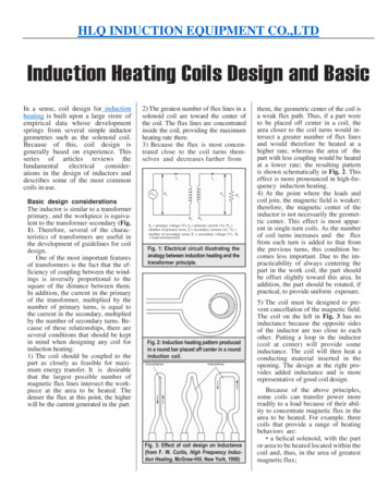
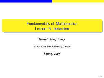
» S ection 2: Choosing Your Coil TypeThe coil is designed to set up a flux field that is perpendicular to the part. The path of theeddy currents is changed to be parallel to the major axis of the work.For example, when manufacturing items such as hacksaw blades, the steel movesbetween the turns of the coil. The eddy-current path is a circular one across the flatof the blade. For heating of wide sheet materials, specially designed transverse-fluxinductors are also available.13. SPLIT-RETURN INDUCTORSUsed when a narrow band of heat is required from one surface only.The center runner of the work coil carries twicethe current of each of the return legs. Thepattern on the workpiece produces fourtimes as much heat under the center leg asin each return loop.With proper balancing, the high-heat pathcan be extremely narrow, while the heatproduced in each return leg will not affectthe rest of the part.14. TAPPED COILSInduction coils can be designed with taps to allow for differences in heated length. Forinstance, heating “off the end” of a bar, where the heating element must be adjusted tothe length.Taps can be brazed to the work coil where a water-cooled strap can be moved from tapto tap. The active portion of the coil will be between the power-supply connection andthe tap.15. BUTTERFLY COILSFor creating an even heating pattern at the end of a bar or shaft.Butterfly coils have two specially formed pancake coils. Center turns must be woundin the same direction so the current paths are additive. Only these center turns shouldcouple directly with the part to produce the desired pattern.The butterfly “wings” may be bent up to decouple their fields from the shaft, or may becoupled with the shaft itself.9
» S ection 2: Choosing Your Coil Type16. COILS FOR INDUCTION SCANNERSUsed for progressive hardening. Built using two methods:Simple single-turn or multiturn coil with a separate quench ring that can be mounted onthe scanner.For larger production runs, a double chamber coil that incorporates both coil coolingand quenching capabilities is often the preferred choice. Cooling water flows from theinductor chamber to keep copper resistivity low. Quenchant is sprayed from perforationsin the beveled face onto the workpiece as it exits.The beveled face is normally at an angle of 300 to the vertical to allow some soakingtime between heating and quenching. This delay helps increase uniformity and reducefluid runback that can cause uneven heating of the workpiece.Well-directed quench spray holes are required inasmuch as “barber poling” can occurdue to erratic or misdirected quenchant that precools the part ahead of the mainquench stream.17. MASTER WORK COILS AND COIL INSERTSUsed for small batches where a single-turn coil can be used.Master work coils provide a simple, rapid means of changing coil diameters or shapesto match a variety of parts. Master work coils typically consist of copper tubing thatprovides both an electrical connection to the power supply and a water-cooled contactsurface for connection to a coil insert.The copper tube is bent into the form of a single-turn coil and soldered to a copper bandthat conforms to the slope of the coil insert and is recessed.Read about designing coil inserts here.18. FLEXIBLE INDUCTION COILSUsed for heating parts like large steel dies, or complex geometry parts, where traditionalrigid coils are not practical due to loading and unloading constraints. Coils are thendesigned with flexible copper conductors located inside flexible non-conducting tubes tobe wound on location. Induction powers up to 200-250kW can be used with these coils.Higher powers are possible with careful manipulation of the cooling water paths in thecoil designs.19. AIR COOLED INDUCTION COILS18. FlexibleInductionCoilThere are some special instances where water cooling inside induction coils is notpractical or required. In these situations, air-cooled copper coils are used for heating.The copper conductors can be constructed with solid copper rods, flexible copperbraids, or litz wires. Certain aerospace and medical applications successfully use aircooled coils for heating.19. AirCooledInductionCoil20. COILS WITH FLUX CONTROLLERSCoils radiate magnetic fields that sometimes heat neighboring metallic fixtures orsupports. This can be avoided by wrapping the outside of the induction coil with aferrite material. The ferrite material captures all the stray magnetic field by offering alow resistance gateway. Since the magnetic field flows through the ferrite there is lesstendency to heat surrounding metal pieces.20. Ferrite Coil10Complete Guide to Induction Coil DesignISO EmblemUsing InductionContactProducts
» S ection 2: Choosing Your Coil TypeTYPICAL COUPLINGEFFICIENCIES FORINDUCTION COILSFrequency10 Hz450 kHzType of coilMagnetic steel Other metalsMagnetic steelOther metalsHelical around irpin0.450.300.600.40One turn around workpiece 00.200.500.25Coil efficiency is the energy delivered to the coil that is transferred to the workpiece.This is NOT the same as overall system efficiency.Typically, helical coils used to heat round workpieces have the highest values of coilefficiency. Internal coils have the lowest values.It is important to note that, with the exception of the pancake and internal coils, theheated part is always in the center of the flux field. Regardless of the part contour, themost efficient coils are essentially modifications of the standard, round coil.A conveyor or channel coil, for example, can be looked at as a rectangular coilwhose ends are bent to form “bridges” in order to permit parts to pass through on acontinuous basis. The parts, however, always remain “inside” the channels where theflux is concentrated.Areas to be hardened are beside the center of the coil turns, and thus are kept in thearea of heaviest flux.INDUCTION COIL APPLICATIONS – WHICH COIL SHAPES ARE TYPICALLY USED?Heat treatingSimple solenoid coils (single- & multi-turn)HardeningMultiple position helical coilsSimple solenoid coils (single- & multi-turn)Progressive HardeningSimple solenoid coils (single- & multi-turn)BrazingSimple solenoid coils (single- & multi-turn)Contoured coils to match the shape of thepart being heated.Channel coilsSolderingSimple solenoid coils (single- & multi-turn)Contoured coils to match the shape of thepart being heated.Channel coilsForgingSimple solenoid coils (single- & multi-turn)Multi position helical coilsElectric MeltingTemperingSimple solenoid coils (single- & multi-turn)Multi position helical coilsInternal bore coils for internal diameterheatingChannel coilsMeltingMulti turn helical coils, having multipleparallel water and electric pathsAnnealingSimple solenoid coils (single- & multi-turn)Multi position helical coilsPancake coils, transverse flux coilsChannel coilsShrink-fittingPancake coils, transverse flux coilsChannel coilsBondingSimple solenoid coils (single- & multi-turn)Multi position helical coilsPancake coils, transverse flux coilsCuringSimple solenoid coils (single- & multi-turn)Multi position helical coilsPancake coils, transverse flux coils11
» S ection 3: Designing Your Induction CoilCOIL DESIGN CONSIDERATIONSCoil design is essential to the effectiveness and efficiency of an induction heating process. This is based on a few things:Basic ConsiderationsCoil efficiencyCoil efficiency is a measure of the energy transferred to the workpiece off the energydelivered to the coil. This is NOT the same as overall system efficiency.Heating pattern requirementsThe heating pattern is a mirror reflection of the coil shape. The design of the coil is themost important factor for determining the heating pattern.Part motion relativeto coilSeveral applications rely on part movement with the help of conveyors, turntables, orrobots. A properly designed induction coil incorporates these individual handling requirements without the loss of heating efficiency.Production rateIf one part is needed every 30 seconds but a 50-second heating time is required, it will benecessary to heat the parts in multiples to meet the desired production rate.Type of power supplySolid state components are preferred in the induction heating power supply as opposed tovacuum tube components. Design should be such that it is flexible, versatile andefficient in converting the energy draw from the grid to the heating process.FrequencyHigher frequencies are used for applications like brazing, soldering, annealing or heattreating, where surface heating is desired. Lower frequencies are preferred for applicationsrequiring through-heating of the parts to the core like forging and die heating.Powder-densityrequirementsHigher power densities are required for short cycle heating applications requiring hightemperatures. Higher power densities may also be required to keep the hot zone confinedto a small area, reducing the heat affected area.Ferrous vs nonferrousFerrous metals heat much more efficiently than non-ferrous metals due to combination ofeddy current and hysteretic heating. They are therefore preferred materials to heat withinduction. However, they should be avoided in the design of holding fixtures for parts asthey may waste energy by heating from the magnetic fields.Start with understanding where the heat needs to be generated in the part to perform the process, and then design thecoil to achieve the heating effect.Matching the coil to the induction power supply is also essential to the efficiency of the process. Frequency-agileinduction systems make it easy to match a wide range of coils with a multi-tap output transformer in the power supply.In addition, material-handling techniques determine what type of coil is needed. If a part will be inserted in a coil,moved on a conveyor, pushed end to end, or if the coil/heat station will move onto the part, the chosen coil design mustaccommodate these movements.SELECTION OF TUBINGBecause of its low resistivity, fully annealed, high-conductivity copper is mostcommonly used for induction heating coils. The copper is typically in a tubular form, with a minimum outer diameter of 0.125in (0.32 cm) to allow for water cooling. Diameters can be as large as 2 in (5.1 cm)for high power applications. Material of this kind is available in a wide range of cross-sections (round, square,and rectangular) and sizes.In addition to the I squared R loss due to its own resistivity, the coil surroundingthe heated part may absorb additional heat through radiation and/or convection.Therefore, it is essential that the tubing selected for the work coil have a sufficientcooling capacity to remove this heat. Otherwise, the resistivity of the copper willincrease due to the temperature increase, thus creating greater coil losses.12Complete Guide to Induction Coil DesignISO EmblemUsing InductionContactProducts
» S ection 3: Designing Your Induction CoilIn some instances, such as large coils, it may be necessary to break up the individual water paths in a coil to preventoverheating and possible coil failure.Another factor in the selection of tubing for induction coils relates to the fact that the current in the workcoils is travelingat a specific reference depth that depends on the power-supply frequency and the resistivity of the copper.Accordingly, the wall thickness of the coil tubing should be selected to reference-depth limits similar to those used forinduction heating of copper. However, copper availability must be considered, and often wall thicknesses less than twicethe reference depth are used with only a nominal loss in overall coil efficiency.Selecting copper tubing wall thickness for induction coils:FrequencyTheoretical wallthickness ( 2 *reference depth (a)),mm (in.)Typical wallthickness available,mm (in.)Minimum tubediameter (b),mm (in.)60 Hz16.80 (0.662)14.00 (0.550)42.00 (1.6550)1800 Hz9.700 (0.382)8.130 (0.320)24.30 (0.9550)540 Hz5.590 (0.220)4.670 (0.184)14.00 (0.5500)1 kHz4.110 (0.162)3.430 (0.135)10.30 (0.4050)3 kHz2.390 (0.094)1.980 (0.078)5.970 (0.2350)10 kHz1.320 (0.052)1.070 (0.042)3.300 (0.1300)450 kHz0.150 (0.006)0.890 (0.035)0.380 (0.0150)1 MHz0.080 (0.003)0.890 (0.035)0.190 (0.0075)(a) Resistivity of copper assumed to be 1.67 * 10 cm (0.66 * 10 in.).(b) Tube ID requirements for adequate cooling-water flow should also be considered.-6-6Square tubingSquare copper tubing is also commercially available and is frequently used in coil fabrication. Offers a considerable advantage in that it couples more flux to the part per turnthan round tubing for tightly coupled coils More easily fabricated - it will not collapse as readily on bending Easily mitered to create sharp, close bends as requiredIf only round tubing is available, it can be flattened in a vise or other simple device to adjust the resultant thicknessdimension. This flattening can be done with minimal decrease in dimension of the water-flow path.13
» S ection 3: Designing Your Induction CoilNUMBER OF COIL TURNSMultiturn coilsIn multiturn coils, as the heated length increases, the number of turns generally shouldincrease in proportion. Multiturn coils of this type are generally utilized for largediameter, single-shot heating.When the length of the coil exceeds 4-8x its diameter, uniform heating at high powerdensities becomes difficult. In these instances, single-turn or multiturn coils that scanthe length of the workpiece are often preferred.Multiturn coils generally improve the efficiency, and therefore the scanning rate, when apower source of a given rating is used.Single-turn coilsSingle-turn coils are also effective for heating bands that are narrow with respect to thepart diameter.The relationship between diameter and optimum height of a single-turn coil variessomewhat with size. A small coil can be made with a height equal to its diameterbecause the current is concentrated in a comparatively small area. With a larger coil, theheight should not exceed one-half the diameter.LEAD DESIGNAll coils represent an
THERE ARE MORE THAN 20 DIFFERENT TYPES OF COILS USED FOR INDUCTION HEATING. Here are their pros and cons, plus some common applications. The helical solenoid coil provides a wide range of heating behaviors since the part or heating area is located within the coil, in the area of greatest magnetic flux. 1. MULTI-TURN HELICAL COIL