Transcription
International Journal of Application or Innovation in Engineering & Management (IJAIEM)Web Site: www.ijaiem.org Email: editor@ijaiem.orgVolume 4, Issue 7, July 2015ISSN 2319 - 4847Design & Manufacturing of Components ofModified Bench Vise on Rapid PrototypeMachineMr. Shrikant M. Chougule1, Prof. D. B. Waghmare 21B.Tech. Mechanical Engg. Dr. Babasaheb Ambedkar Tech. University, Lonere, Dist- Raigad, Maharashtra(India)2Asst. Professor, Dept. of Mechanical Engg. Dr. Babasaheb Ambedkar Tech. University, Lonere, Dist- Raigad,Maharashtra(India)ABSTRACTPrototyping or model making is one of the important steps to finalize a product design. Traditional Rapid Prototyping (RP) iscommonly referred to as layered manufacturing or solid free form fabrication. It is used for the physical modelling of a newproduct design directly from computer aided design (CAD) data without the use of any special tooling or significant processengineering. This rapid procedure reduces the lead time required to produce a prototype of a product by eliminating much orall of the process engineering time and tooling requirements. It helps in conceptualization of a design. Designing a rigid,flexible, cost effective and highly durable vise is need of today’s era. Safety should also be taken into consideration whiledesigning the vise. This paper is related to designing and manufacturing of modified bench vise components on rapid prototypemachining process. We have designed the conventional and modified bench vise in Pro-E CAD software and manufactured iton Dimension 1200es RPT machine.Keywords: Rapid Prototyping, Rapid Tooling, Rapid Manufacturing, Bench Vise, Value Addition1. INTRODUCTIONVise is a mechanical screw apparatus used for holding or clamping a work piece to allow work to be performed on itwith tools such as saws, planes, mills, drills, screwdrivers sandpaper, etc. Vises usually have one fixed jaw and another,parallel jaw which is moved towards or away from the fixed jaw by the screw. Vises are used as holding devise onmachines like lathes, milling machine, drilling machine etc. and also by tool makers for holding jobs. Design wise threetypes of vises are very common in use namely plain vise, swivel vise and tool maker’s vise which is commonly knownas bench vise. Vise is usually refers to a bench vise with flat, parallel jaws, attached to a workbench. There are twomain types: a woodworking vise and engineer's vise. The woodworker's bench vise main characteristic is its integrationinto the bench. An engineer's bench vise is usually clamped or bolted onto the top of the bench. The handle is usuallyadjustable so that it can be tightened in small places.There are four main types of bench vises these are machinist vise, mechanics vise, post vise and woodworkers vise. Themachinist's vise is considered as "cream of the crop". They are stoutly made and are finely machined. The jaws shouldmatch up perfectly, and they will be made of very high grade (60,000psi or greater) cast iron. The mechanic's vises aremade of lower grade iron. They usually have an integrated anvil area. The post vise is a blacksmith's tool, these visesare made of forged wrought iron, not cast iron, allowing them to have ductility. The woodworker's vise is an undermount vise, usually with a retractable dog for clamping work upon the workbench.There are two main types of jaws used on vises: hard and soft. Hard jaws are available with either a coarse grippingsurface or are ground flat and smooth to increase accuracy. The latter relies on pressure for gripping, instead of a roughsurface. An unskilled operator has the tendency to over tighten jaws, leading to part deformation and error in thefinished workpiece. Soft jaws are usually made from a soft metal (usually aluminum), plastic, or wood. They are used toeither hold delicate workpieces. These specifically cut jaws are often used in place of fixtures and most commonly usedin gang operations. They are also used for rapid change-over type set-ups since they can be easily engraved with thepart number, the job number, or other information relevant to the job being run. Soft jaws are considered a consumableitem, because they are discarded or recycled after multiple uses.2.Rapid PrototypingPrototyping or model making is one of the important steps to finalize a product design. It helps in conceptualization ofa design. Before the start of full production a prototype is usually fabricated and tested. Manual prototyping by a skilledcraftsman has been an age old practice for many centuries. Second phase of prototyping started around mid-1970s,when a soft prototype modelled by 3D curves and surfaces could be stressed in virtual environment, simulated andtested with exact material and other properties. Third and the latest trend of prototyping, i.e., Rapid Prototyping (RP)Volume 4, Issue 7, July 2015Page 39
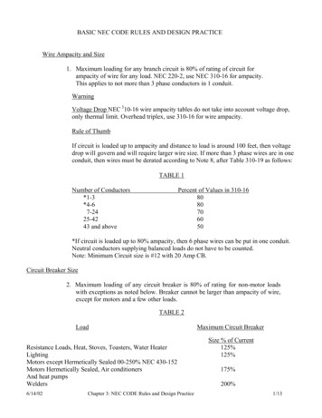
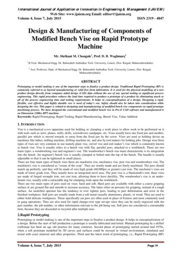
International Journal of Application or Innovation in Engineering & Management (IJAIEM)Web Site: www.ijaiem.org Email: editor@ijaiem.orgVolume 4, Issue 7, July 2015ISSN 2319 - 4847by layer-by-layer material deposition, started during early 1980s with the enormous growth in Computer Aided Designand Manufacturing (CAD/CAM) technologies when almost unambiguous solid models with knitted information ofedges and surfaces could define a product and also manufacture it by CNC machining.Rapid Prototyping (RP) is capable of producing prototypes of almost any geometrical complexity in relatively short timeusing the additive manufacturing approach.RP is a technology for quickly fabricating physical models, functionalprototypes and small batches of parts directly from computer aided design (CAD) data. RT (Rapid tooling) generallyconcerns the production of moulds and tooling inserts using RP. Figure 1.2 various applications and processes of rapidprototyping.Fig. 1.2 Applications of rapid prototypingThe rapid prototyping (RP) process is being used widely with great potential for rapid manufacturing of functionalparts. The RP process involves translation of the CAD file to STL (standard triangular language) format followed byslicing of the model into multiple horizontal layers, each of which is reproduced physically in making the prototype.The thickness of the resulting slices has a profound effect on the surface finish and builds time of the prototype. Threeobjects were modelled and STL files were generated. One STL file for each object was sliced using different slicethicknesses, and the build times were obtained. Screenshots were used to show the slicing effect on layering error andsurface finish and to demonstrate the means to a more efficient STL file. Rapid prototyping is an innovatingmanufacturing technology with inherent capability to transform CAD models directly into physical parts, therebypositively influencing product development effort on time, cost and quality fronts.2.1 Fused Deposition Modeling TechnologyFused deposition modeling (FDM) is gaining distinct advantage in manufacturing industries because of its ability tomanufacture parts with complex shapes without any tooling requirement and human interface. Method of RapidPrototyping (RP) is most commonly used for rapid production of new part intended for presentation purposes.Manufactured models can also be used for different tests and analyses, for example for testing of fluids flow,aerodynamic tests, confirmation of results of FEM and DEM analyses. Another application area is covered withverification of assembling procedures and checking on their kinematical and dynamical properties. Typical examplesare successfully created proto types or reconstructions of bones, joints. Created prototypes dramatically increase level ofpossible engineering interaction, as real 3D objects are easier to explain and understand as presented 2D ideas ofmodels. For testing purposes the models can be printed in scale what can lead to lower requirements for testing forces,Volume 4, Issue 7, July 2015Page 40
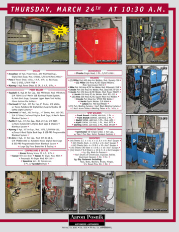
International Journal of Application or Innovation in Engineering & Management (IJAIEM)Web Site: www.ijaiem.org Email: editor@ijaiem.orgVolume 4, Issue 7, July 2015ISSN 2319 - 4847loads, etc. RP technology also shortens times for classical prototyping in sense of creating-testing-redesigningrebuilding and repeatedly.For better orientation of user in process of setting of suitable parameters during the preparation of printing there wasalgorithm elaborated which accumulates all factors and steps that lead to selection of most suitable variant. All theattempts were realized as a part of preparation stage for printing on RP machine that utilize FDM technology to buildthe prototype. This technology, developed by Stratasys, uses the software program to orient the model and generatebuilding slices. Printer dispenses with basic building material and support material which is used if necessary forcreation of holes, cavities, drafts, etc. Each material has its own nozzle. Creation of particular prototype layers with useFDM method is shown in following figure1.3.Fig. 1.3 Schematic model of FDM (1-nozzle, 2-building material, 3-movable table) (11)2.2Types of RP SystemsPrototyping is an important stage in any product development process and the prototype can be defined as “anapproximation of a product (or system) or its components in some form for a definite purpose in its implementation”There are three main Rapid Prototyping systems, depending on initial the form of materials involved: Liquid-based RP systems – The initial form of material is in liquid state and, by a curing process, the liquid isconverted into solid state; the system includes: 3D Systems’ Stereolithography (SLA), Light Sculpting, Rapid Freezeand Two Laser Beams Solid-based RP systems – The initial form of material is in solid state, except for powders (wire, roll, laminates,pellets); this system includes: Stratasys ‘Fused Deposition Modeling (FDM), 3D Systems, Multi-Jet ModelingSystem(MJM) and Pares lamination Technology (PLT) Powder-based RP systems – The initial form of material is powder; the system includes: 3D Systems, Selective LaserSintering (SLA), Precision Optical Manufacturing’s Direct Metal Deposition (DMD) and Z Corporation’s ThreeDimensional Printing (3DP).2.3 Basic Principle of Rapid Prototyping ProcessesRP process belong to the generative (or additive) production processes unlike subtractive or forming processes such aslathing, milling, grinding or coining etc. in which form is shaped by material removal or plastic deformation. In allcommercial RP processes, the part is fabricated by deposition of layers contoured in a (x-y) plane two dimensionally.The third dimension (z) results from single layers being stacked up on top of each other, but not as a continuous zcoordinate. Therefore, the prototypes are very exact on the x-y plane but have stair-stepping effect in z-direction. Ifmodel is deposited with very fine layers, i.e., smaller z-stepping, model looks like original. RP can be classified intotwo fundamental process steps namely generation of mathematical layer information an generation of physical layermodel. Typical process chain of various RP systems is shown in figure 2.1.Fig. 2.1 RP process chain showing fundamental process stepsVolume 4, Issue 7, July 2015Page 41
International Journal of Application or Innovation in Engineering & Management (IJAIEM)Web Site: www.ijaiem.org Email: editor@ijaiem.orgVolume 4, Issue 7, July 2015ISSN 2319 - 4847It can be seen from figure 2.1 that process starts with 3D modelling of the product and then STL file is exported bytessellating the geometric 3D model. In tessellation various surfaces of a CAD model are piecewise approximated by aseries of triangles and co-ordinate of vertices of triangles and their surface normals are listed. The number and size oftriangles are decided by facet deviation or chordal error. These STL files are checked for defects like flip triangles,missing facets, overlapping facets, dangling edges or faces etc. and are repaired if found faulty. Defect free STL filesare used as an input to various slicing softwares. At this stage choice of part deposition orientation is the mostimportant factor as part building time, surface quality, amount of support structures, cost etc. are influenced. Once partdeposition orientation is decided and slice thickness is selected, tessellated model is sliced and the generated data instandard data formats like SLC (stereolithography contour) or CLI (common layer interface) is stored. This informationis used to move to step 2, i.e., generation of physical model.The software that operates RP systems generates laser-scanning paths (in processes like Stereolithography, SelectiveLaser Sintering etc.) or material deposition paths (in processes like Fused Deposition Modelling). This step is differentfor different processes and depends on the basic deposition principle used in RP machine. Information computed here isused to deposit the part layer-by-layer on RP system platform. The generalized data flow in RP is given in figure2.2.The final step in the process chain is the post-processing task. At this stage, generally some manual operations arenecessary therefore skilled operator is required. In cleaning, excess elements adhered with the part are removed.Sometimes the surface of the model is finished by sanding, polishing or painting for better surface finish or aestheticappearance. Prototype is then tested or verified and suggested engineering changes are once again incorporated duringthe solid modelling stage.Fig. 2.2 Generalized illustration of data flow in RP3. Case StudyThe Manufacturing industry is operating on tighter margins and ever increasing competition. With more competitionand ever changing consumer demands, small scale industries are frequently realizing the necessity to reengineer theirfacility to satisfy the needs of many product groups and styles.In the Mechanical Engineering field bench vise plays a vital role during manufacturing of various components.Therefore we have selected the bench vise for the case study. In market different types of bench vises are available tomeet the industry demand but till the existing bench vise can be modified in different types to complete the operationssafely, efficiently and to increase the productivity of manufacturing industry. We have manufactured the proposedmodified bench vice by using Rapid Prototyping process.3.1 ObjectivesEvery organization attempts to reduce the costs through number of ways. Effective control of costs is one of theimportant functions of management. Rapid prototyping technique is aimed to finalize a product design. It helps inVolume 4, Issue 7, July 2015Page 42
International Journal of Application or Innovation in Engineering & Management (IJAIEM)Web Site: www.ijaiem.org Email: editor@ijaiem.orgVolume 4, Issue 7, July 2015ISSN 2319 - 4847conceptualization of a design. Before the start of full production a prototype is usually fabricated and tested. It helps toimprove effectiveness of work, design, method of manufacture of the product eliminating unnecessary costs withoutadversely affecting quality, safety and other customer features.It also involves a systematic consideration of alternative methods of accomplishing required functions and alternativematerials, processes. Rapid prototyping technique is used to increase the effectiveness of the final product beforemanufacturing. Therefore Rapid prototyping is used for cost reduction and design modification of bench vise.Rapid prototyping manufacturing technology has a capability to transform CAD models directly into physical parts,thereby positively influencing product development effort on time, cost and quality. Vises are used as holding devise onmachines like lathes, milling machine, drilling machine etc. and also by tool makers for holding jobs i. e. vise is usedon large scale for different applications. So it is necessary to design a rigid, flexible, cost effective and highly durablevise. Safety should also be taken into consideration while designing the vise. Present work is to design a bench visewith modifications in conventional vise. Consequently the main objective of this work is to make modifications inpresent vise and manufacture its prototype on RPT machine.The main objectives of this project are:1. Study of Rapid Prototyping and bench Vise.2. Designing a conventional bench vise using Pro-E.3. Design modification by value addition in the bench vise.4. One side locking arrangement (C Clamp with one screw) for bench vise to make it portable& fix bench vice ondifferent tables at any location.5. Providing surface plate with right angle plate on stationary jaw for measurement of right angles between two surfacesof job.6. Manufacturing a prototype of modified bench vise on RPT machine.7. Making bench vise more cost effective and reliable.4. Design ProcessDesign process can be achieved by relying on new design methods and with the help of computer programs likeCATIA. The advantage of using these options when designing these product variants is the speed of manufacturing andtime to market and the result is reduction of cost production. The overall process of design, from beginning to end, isdefined in following figure. The process begins with identification of need and then making the decision. After muchiteration, the process ends with the presentation of the project which fulfils the request.4.1 Design of Bench ViseFollowing details and exploded view of Bench vise is designed in Creo parametric (Pro-E) designing software.Designing ( drafting and 3D orientation ) of each seprate part is also added in following sections.Fig. 4.5 Different components of bench vise shown in exploded viewExploded view of assembled bench vise is shown in figure 4.5.Table no.4.1 Bill of materials of conventional bench viseSr. No.Part nameQuantityMaterial1Fixed jaw1C. I.2Jaw plate2SAE 31403Handle rod1CRS4Handle nut1SAE 10205Flat tapping screw4MILD STEEL6Vise screw1SAE 3140Volume 4, Issue 7, July 2015Page 43
International Journal of Application or Innovation in Engineering & Management (IJAIEM)Web Site: www.ijaiem.org Email: editor@ijaiem.orgVolume 4, Issue 7, July 201578CollarSliding jaw11ISSN 2319 - 4847SAE1020C. I.Design of each part of bench visePro-E is parametric integrated 3D CAD/CAM/CAE solution created by Parametric Technology Corporation (PTC). Itprovides solid modelling, assembly modelling and drafting, finite element analysis, direct and parametric modelling. Itis more user friendly than any other CAD software for solid modelling. Hence we decided to carry out the designing ofour bench vise in Pro-E CAD software. While designing there are various processes which described below every partdesign figure.Design of vise screw3D orientation of vise screwFront and L.H. S. view of vise screw (Scale 1.67:4.00)The function of vise screw of bench vise is to give the movement for movable jaw in to and fro direction. This is usedfor tightening the work piece in fixed and movable jaws. It is manufactured by usnig material of SAE 3140.Design of collarCollar is circular ring that goes round a vise screw to make it stronger, especially where screw head and movable jaware to be joined for movement purpose of the movable jaw. It located between screw head and base of movable jaw. Italso gives the strong support to the screw head at the time of tightening the work piece between the jaws. Generally it ismade of SAE 1020 material.3D orientation, front& L.H.S. view of Collar (Scale 1.0:1.5)Design of jaw plateJaw plate is simple metallic strip made from SAE 3140 material. It is fixed on the both movable and fixed jaw. Itsfunction is to grip the work piece firmly when different operations are to be performed on the work piece. For effectivegrip, diamond knurling is provided on gripping surface. Depending upon the material of work-piece, different jawplates can be used as per requirement.Front & L.H.S.W. of Jaw plate (Scale 0.500:1.000)Design of sliding jawSliding jaw is also called as movable jaw which is used to hold the work-piece between movable and fixed jaw.Depending upon the size of work-piece, the sliding jaw can be operated in to and fro direction to hold the work-piece.Volume 4, Issue 7, July 2015Page 44
International Journal of Application or Innovation in Engineering & Management (IJAIEM)Web Site: www.ijaiem.org Email: editor@ijaiem.orgVolume 4, Issue 7, July 2015ISSN 2319 - 4847Generally it is made from cast iron (CI). It is a rigid part of bench vise to remain stable when the operations are carriedout.Front and left hand side view of sliding jaw (Scale 0.143:0.300)Design of vise handleThe function of vise handle is to give the rotating motion to vise screw when tightening and loosening of work-piecebetween two jaws are required. It is inserted in the hole provided on vise screw. On one side of vise handle threadedportion is provided and other side is ball headed. It is made from CRS material.Front and L. H. S. view of handleScale ( 0.333: 0.900 )3D orientation of vise handleDesign of handle nutThis nut is fixed on vise handle. Its function is to restrict the vice handle from falling down from the vise screw. It ismade from the material MS.3D orientation, front and L. H. S. view of handle nut (Scale 1.00:1.60)Design of flat tapping screwThe tapping screw is used to fix the jaw plate on the face of the both jaws i.e. sliding and fixed jaw which is used tohold the work-piece. It is tightened with the help of Allan key. Generally two tapping screws are required for each jawand are manufactured in MS.Front and L. H. S. view of tapping screw (scale 1.000:3.000)Design of fixed jaw of bench viseThe fixed jaw is the main part the bench vise which supports the whole assembly of bench vise. The fixed jaw is rigidlyfixed on work bench with the help of nut and bolt arrangement on both sides. Its function is to guide the movable jawand vise screw which are operated in to and fro direction. Fixed jaw is manufactured form cast iron (CI) metal. TheVolume 4, Issue 7, July 2015Page 45
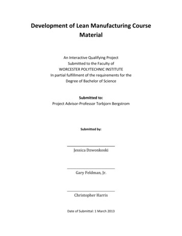
International Journal of Application or Innovation in Engineering & Management (IJAIEM)Web Site: www.ijaiem.org Email: editor@ijaiem.orgVolume 4, Issue 7, July 2015ISSN 2319 - 4847work piece is held between fixed jaw and movable jaw hence while performing operations on work piece thermalstresses and large forces are applied on the work piece. For this reason movable jaw should be thermal resistant andshould be able to withstand with large amount of forces.Front and L. H. S. view of fixed jaw (scale 0.143:0.300)4.2 Modifications Made in the Design of Bench ViseOur project is based on making modifications in the existing conventional bench vise and then designing it on CADsoftware (Pro-E). We have made some modifications in conventional bench vise and redesigned it on CAD software.The detail explanation about the modifications is explained below.Design of modified fixed jawIn this modification tradition fixed jaw is modified in such a way that it should take the shape of surface plate. Thismodification will help to insure that either two faces are in 90 degree or not. When it is necessary to measure the90degree angle between any two faces repetitively then this modification will saves time. During this modification someof the material is removed from fixed jaw so it costs very less. This cannot be used for measurement of job havingdimensions more than 90*92 mm.Front and L. H. S. view of modified fixed jaw (scale 0.143:0.300)Design of C-clampMost of the traditional bench vises are attached or clamped to a bench permanently with the help of two or three bolts.So we cannot use these traditional vises as portable devise. Whenever it is fixed to one location it gets fixedpermanently till we don’t remove the bolts. Removing all bolts and attaching this bench vise to different location is verytime consuming and difficult job, hence C-clamp is designed which can be attached below the base of traditional fixedjaw, with matching its dimensions. Whenever we need to change the location of bench vise then first attach the c-clampto vise permanently with the help of nut and bolt arrangement and use it over the bench. This arrangement cannot beused for bench thicker than 88 mm.This type will be designed in such a manner that it should save the clamping time and material of bench vise. It isdesigned with only one screw for fixing it on fixed jaw which intern saves machining time and cost of c-clamp.Stability wise it is less stable than previous clamp but most suitable for small job. In this type of clamp fluctuational andvibrational problems may arise during work on heavy jobs.Front and L. H. S. view of modified c-clamp (Scale 0.250:0.500)Volume 4, Issue 7, July 2015Page 46
International Journal of Application or Innovation in Engineering & Management (IJAIEM)Web Site: www.ijaiem.org Email: editor@ijaiem.orgVolume 4, Issue 7, July 2015ISSN 2319 - 4847Design of clamping screwClmping screw is design fit into the c-clamp and at the top of the clamping screw circular dics is provided to fit thebench between circular disc and base of fixed jaw. The designing dimenssions of the clamping screw are given infolowing figure.Front and L. H. S. view of clamping screw (Scale 0.500:1.000)3D orientation of clamping screwDesign of circular discThis circular disc is mounted on clamping screw to hold the bench wise. The upper face of the disc should provide goodresistant to bench to hold it properly against bench. Inner threads are provided at lower portion of circular disc to attachcircular disc. Circular disc is made up of MS.3D orientation, Front and L. H. S. view of circular disc used in c-clamp (Scale 1.0:1.2)Design of handle for c-clampThis handle is used for rotating clamping screw. The hole is provided at the top of the handle to accommodate handle.This handle is rotated by applying torque to fit the bench vise to the bench.Front and L. H. S. view of handle used for c-clamp(Scale 0.500:1.500)3D orientation of handle used in c-clampDesign of handle capTo lock the handle from one side this handle cap is provided. This handle serves as a locking system and made up ofsame material as that of handle. The shape and size of the handle cap is as shown in fig. below.3D orientation, Front and L. H. S. view of handle cap (Scale 2.00:3.00)Volume 4, Issue 7, July 2015Page 47
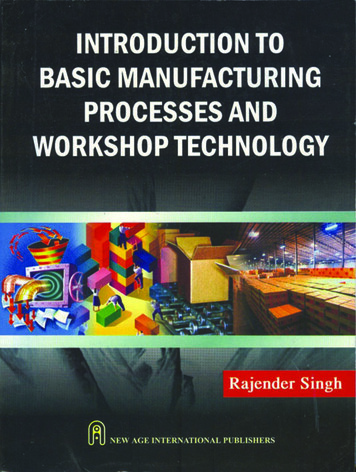
International Journal of Application or Innovation in Engineering & Management (IJAIEM)Web Site: www.ijaiem.org Email: editor@ijaiem.orgVolume 4, Issue 7, July 2015ISSN 2319 - 4847Actual pictures after modifications in CAD softwareThe main components of modified bench vise are fixed jaw, movable jaw, lead screw with handle, c-clamp, clampinghandle, nut and bolt.The fixed jaw is fixed to the c-clamp with base with the help of nut and bolt. A lead screw is fit between movable jawand fixed jaw to control the movement of movable jaw. The whole assembly is then fitted to bench with help of c-clampas shown in fig. The work piece is held between movable jaw and fixed jaw with the help of lead screw.Fig. 4.7 Highlighted C-clamp is fixed to bench vise with one screw5.Rapid Prototyping of Bench ViseDimension 1200es printers are designed with ultimate simplicity in mind. The systems enable you to build partsquickly, even if you have never used a 3D printer before. The systems model with ABS plus plastic, so modeled partsare strong and durable. ABS plus so ensures that you will be able to drill, tap, sand, and paint your creations. With thespeed and convenience of Soluble Support Technology, completed parts are quickly available for review and test.Dimension 1200es printers are an innovative combination of proprietary hardware, software, and material technology.Dimension 1200es printers build models, including internal features, from CAD STL files. Three dimensional parts arebuilt by extruding a bead of ABS plastic through a computer-controlled extrusion head, producing high quality partsthat are ready to use immediately after completion. With two layer resolution settings, you can choose to build a partquickly for design verification, or we can choose a finer setting for higher quality surface detail. The Dimension 1200essystems consist of two primary components-the Dimension 1200es 3Dprinter and Catalyst EX. Catalyst EX is thepreprocessing software that runs on a Windows XP Pro, Windows Vista or Windows 7 platform. The build envelopemeasures 254 x 254 x 305 mm (10 x 10 x 12 in). Each material cartridge contains 922 cc (56.3 cu. in.) of usablematerial (10).Table. 5.1 Manufacturing details of various parts of bench viseModelSupportEstimatedWeightName of PartsMaterial (in3)Material (in3) Time (Hrs)(gm)Movable Jaw3.622.055.3657.3Fixed Jaw3.261.596.0283.3Vise screw with handle0.520.461.328.2C-clamp fixing 040.010.041.9Screw0.020.010.061.6Assembly 17.524.1612.94150.3Assembly 28.054.3213.38153.5Assembly 37.484.1312.78149.1Assembly 1: Assembly of conventional bench viseAssembly 2: Assembly of modified bench vise with C-clamp having one screwAssemble 3: Assembly of movable jaw and modified fixed jaw5.2Manufacturing of modified Bench vise on RPTFor better visualization we used Catalyst Ex software which gives model material, support material, model cartridgeand support cartridge in cubic inch. Also it gives estimated time for manufacturing of part.1. Fixed jawVolume 4, Issue 7, July 2015Page 48
International Journal of Application or Innovation in Engineering & Management (IJAIEM)Web Site: www.ijaiem.org Email: editor@ijaiem.orgVolume 4, Issue 7, July 2015ISSN 2319 - 4847Inserting STL file - orientating as per requirement (minimum support material should be used) - packing it for finalprinting (locating its position on base clamp) – checking availability of enough material for manufacturing a packedpart and printing finally on rapid prototype machineFig.5.3 Visualization of fixed
as bench vise. Vise is usually refers to a bench vise with flat, parallel jaws, attached to a workbench. There are two main types: a woodworking vise and engineer's vise. The woodworker's bench vise main characteristic is its integration into the bench. An engineer's bench vise is usually clamped or bolted onto the top of the bench.