Transcription
EXCEL MODULAR SCAFFOLD REV CCUSTOM COMPONENT &SPECIALTY TECHNICAL MANUALEMSLC-TSM-1001Engineering Approval: Lance SmithRelease Authorization: ECN EMSLC-0189Manual Release Date: 12/03/2016Revision: C
REVISIONS FROM PREVIOUS EDITIONLIST OF SECTIONS CHANGEDAdjustable Horizontal BearerAdjustable Horizontal BearerSnow LaddersRight-Angle BraceScaffold CartAdjustable Horizontal Bearer Deck LoadingAdjustable Horizontal Bearer Max Deck LoadingBeam Trolley Splice KitsSafety OutriggerTie-Off Anchorage PointTruss Description (Updated Verbiage)Seismic Scaffold CriteriaLanding Hatchway **Aluminum Deck Boards **Grating Deck Boards **Heavy Duty Beam Clamp **Horizontal Members with Locking Latch**Boiler Equipment **Roof Adapter**Skid Pan**ATCA**Counter Weight Base Plate**Counter Weight Base Plate**Scaffold Lifting Devices**Trolley System**Beam Trolley Splice Kits**Trolley System Components**Shoring System**Aluminum Ladders**SRL Adapter**Sample SRL Installation**Rapid Access System**Aluminum Stair Bay**Ladder Cages**Walkway Support System**Reconfigure Manual for Ease of UsePAGEB-9B-10J-5J-7S-CartB-11B-12H-5E-2T-1 to T-4H-1S-1 to S-5F-1G-3G-2AB-1 to AB-2B-1AV-1I-1AJ-1AC-1Y-1Y-2U-1H-4H-5H-6AD-1 to AD-2 & AE-1J-4T-5T-6Z-1 to Z-3N-2J-6X-1ALL**Part removed from Excel Technical Manual and placed in this Excel Custom/Specialty Parts /20063/3/20135/13/201212/31/200501/30/2016
TABLE OF CONTENTSRevisions From Previous Edition iIntroduction iiIntended Use of Excel Modular Scaffold iiiAluminum Pick Board 1Excel Modular Landing Hatchway (LH) 2Excel Modular Grating Board (DGP)** 3Excel Modular Duckbill Steel Planks 4Bracing Excel Boiler Components 53 1/2” x 2” Swivel Clamp (BAC) 6Excel Modular Specialty Beam Tube Clamp (BBC) 7Excel Modular Universal Beam Tube Clamp (UBTC) 8, 9Excel Modular Vertical Leg Hanging Bracket (VLHB) 10Lifting & Moving Excel Modular Scaffold 11Excel Modular Skid Pans (SKID 8 & 10) 12Adjustable Tube & Clamp Adapter (ATCA) 13Excel Modular Roof Adapter (RA) 14Excel Modular Counter Weight Base Plate (CWBP) 15, 16Excel Modular Trolley System 17, 18, 19, 20Excel Modular Davit Arm (DAVIT1) 21Excel Modular SRL Adapter 22, 23Excel Modular Aluminum Gate Toe board 24Excel Modular Tie Off Lug (TOL)** 25Excel Modular Elevator Strut Assembly (ESA) 25Excel Modular Aluminum Ladders 27Excel Modular Aluminum Stair System 28Excel Modular Ladder Cage 29Excel Rapid Access System 30, 31, 32Excel Modular Shoring Post 33, 34Excel Modular Shoring Jacks 35Excel Modular Walk-Through Filler (Base) Plates (WTFP) 36Design of Seismic Scaffolding 37, 38, 39, 40, 41** Special order items. For purchase only.
INTRODUCTIONThe Excel Scaffold Custom/Specialty Manual contains components not found in the Excel Standard ComponentTechnical Manual. This is a supplemental manual to be used in conjunction with the standard manual.All components found in this manual fall under the same standards and conditions found in the StandardComponent Technical Manual.Some items found in the Custom/Specialty Manual are for sale only, or take additional lead time tomanufacture. Please ensure of the availability of components prior to ordering.This manual does not replace the OSHA 1926/1910 and/or CAL-OSHA documents.1. Compatibility of Excel Modular Scaffold:Excel scaffold is designed and engineered to be compatible with standard tube & clamp components (i.e.: clamps,poles, ladders and ladder brackets) that are currently available within the scaffold industry. These tube & clampcomponents are generally used for: Tube & clamp for tie-offs when needed for seismic considerationsWhen needed to transition horizontally to get around obstaclesWhen needed to transition vertically to get around interferenceLadders and ladder brackets for access to work platformsAs needed for structural bracing and reinforcement2. General erection criteria:Excel was designed and engineered to be constructed using the same requirements specified by OSHA and CAL-OSHA,that have been historically used with tube & clamp and other system type scaffolds.Excel expects all users to be familiar with all Federal, State and local regulations governing scaffold construction and use.Excel expects all users to erect, modify or dismantle scaffolding using only qualified and competent personnel withadequate supervision.Excel expects all users to provide supervision that is competent and qualified, and who can inspect and sign off on eachscaffold before authorization is given for general use.Excel expects all users to follow all common safety guidelines including: pre-job briefings, procedure compliance, tagging,flagging, wearing of proper PPE, weight-loading restrictions, vertical leg placement, use of diagonal bracing, horizontalwraps, proper use of handrails, mid-rails, toe boards, safety netting, screw jacks, ladders, metal or wood decking, etc.Excel expects all users to utilize a registered professional engineer (licensed PE) to design and approve drawings, asrequired by OSHA, CAL-OSHA or any other regulatory agency.3. Special considerations:Be extra careful when working with components that telescope.Telescoping components can move/slide while being transported, handled and passed to other workers.Many Excel scaffold components swivel, slide or hinge. Use caution when passing to other workers, transporting andinstalling these items.Ensure that all items containing locks or pins are secured before handling, transporting or passing these items to another worker.All material must be inspected prior to use! See Section R of the Standard Component Technical Manual forInspection guidelines.EMSLC-TSM-1001Page iiRevised: 12/03/16
INTENDED USE OFEXCEL MODULAR SCAFFOLD1. Unless otherwise stated, all load data presented in this manual includes the OSHA (4:1) Safety Factor.2. Unless otherwise stated, all load data presented in this manual is for downward or compressive loading only.3. Excel’s scaffold material, when constructed for normal use, is not designed to be up- or side-loaded in excess of OSHAand ANSI requirements. When conditions require special loading, extra design features must be added to ensure properstability.4. Once installed and completed, scaffold should be considered part of the customers plant equipment. Abuse or mistreatmentof the scaffold material should not be tolerated.5. The scaffold material should be inspected for damage and repaired after any incident which could affect the integrity of thescaffold material such as: The scaffold comes into contact with any moving equipment, forklifts, trucks or trailers, and other types of mobileequipment. The scaffold is affected by an unintended load, flanges or piping attached to a crane or come-along, objects droppedfrom above or swung in from the side, etc. Excessive force is applied to the scaffold from abuse or accidental contact. The material is modified in any way with a torch, saw or other equipment. The material is affected from corrosive chemicals that remove the coating and/or damage the base metal. The material is bent or otherwise damaged.6. The end-user should ensure that their competent, qualified individuals and scaffold erection personnel are trained and fullyunderstand the above requirements.7. When testing of material is required, it should be conducted by qualified personnel in a testing environment. Field testing ofscaffold components should not be conducted without a formal test plan approved by the manufacturer.8. All end-users must be trained in the proper use of Excel Modular Scaffold. The tech manual is provided as a reference fortraining. New users should examine the Key Rules at the end of the manual.9. OSHA requires that inspections must be made by the scaffold builder and end-user.All material must be inspected prior to use! See Section R of the Standard Component Technical Manual forInspection guidelines.EMSLC-TSM-1001Page iiiRevised: 12/03/16
ALUMINUM WALKBOARDSPart NumberDescriptionWeight (lbs)Uniform Loadlbs./ft.Center Loadlbs.AB77’x 19” Aluminum Walkboard30.5112600AB88’x 19” Aluminum Walkboard37.5112600AB1010’x 19” Aluminum Walkboard46.5112600Aluminum boards are designed for use in applications when the weight of standard metal boards are a concern or when theuse of aluminum may be preferred over galvanized metal decking.Additional lead time may be required when ordering aluminum boards.Note:Where a possibility of uplift could occur, all boards should be securely attached to the scaffold with #9 wire, tie wraps,toeboards, filler plates or other equivalent means.All material must be inspected prior to use! See Section R of the Standard Component Technical Manual forInspection guidelines.EMSLC-TSM-1001Page 1Revised: 12/03/16
EXCEL MODULAR LANDINGHATCHWAY (LH)Always install hatches from the bottom, NEVER from above.PartNumberDescriptionWeight (lbs)OpeningDimensionsFits Bay SizesMaximum Distributed LoadLoad on Hatch with AllBoards InstalledLHLanding Hatchway32.028”x28”36” to 60”36 lbs./sq ft.*Note:1. The load carrying ability of the decking boards may be the limiting factor.2. The Landing Hatchway is not designed to support weight until all boards are installed.Never stand or place a load on a hatchway until all deck boards are properly installed.All material must be inspected prior to use! See Section R of the Standard Component Technical Manual forinspection guidelines.EMSLC-TSM-1001Page 2Revised: ##/##/##
EXCEL MODULAR GRATING BOARDS(DGP) (For Purchase Only**)Part NumberDescriptionWidthInchesWeight lbs.Uniform Loadlb/ft.Center Load lbs.GP242’ Grating Plank930.0548600GP3232” Grating Plank935.0351600GP363’ Grating Plank937.5244600GP4242” Grating Plank942.0179546GP484’ Grating Plank945.0137520GP605’ Grating Plank952.588480GP726’ Grating Plank960.061388GP847’ Grating Plank967.534322Grating boards are designed with standard 1 1/4” deck grating to fit standard scaffolds. This provides greater openings fordebris and liquids when drainage is important.Additional lead time may be required when ordering grating, as well as additional cost.All material must be inspected prior to use! See Section R of the Standard Component Technical Manual forinspection guidelines.EMSLC-TSM-1001Page 3Revised: 12/31/05
EXCEL MODULAR DUCKBILL PLANKSPart NumberDescriptionWidth(Inches)Weigh (lbs.)Uniform Load(lbs./ft.)Center Load(lbs.)DBP242’ Duckbill Plank912.5271600DBP363’ Duckbill Plank917.0271600DBP4242” Duckbill Plank919.0232546DBP484’ Duckbill Plank919.8213520DBP605’ Duckbill Plank924.5185480DBP726’ Duckbill Plank929.5105388DPB847’ Duckbill Plank931.5100322DBP968’ Duckbill Plank938.593284DBP1089’ Duckbill Plank942.569250DBP12010’ Duckbill Plank947.5582336DBP246”x 2’ Duckbill Plank610.52716006DBP366”x 3’ Duckbill Plank612.92716006DBP426”x 42” Duckbill Plank614.52325466DBP486”x 4’ Duckbill Plank616.12135206DBP606”x 5’ Duckbill Plank619.41854806DBP726”x 6’ Duckbill Plank622.61053886DBP846”x 7’ Duckbill Plank625.91003226DBP966”x 8’ Duckbill Plank627.7932846DBP1086”x 9’ Duckbill Plank632.4692506DBP1206”x 10’ Duckbill Plank635.658233Note:1. Overlapping Steel Planks (Duckbill Plank (DBP)) can be used to fill gaps in decks created by obstructions. They rest on thetwo adjacent steel planks or steel planks and bearer, thereby reducing the need for wood planking.2. DBP are to be attached to the planks they are resting on by way of #9 wire, or tech screws through the holes provided inthe DBP.3. The loading of the DBP and adjacent planks must be taken into consideration when designing the scaffold.All material must be inspected prior to use! See Section R of the Standard Component Technical Manual forinspection guidelines.EMSLC-TSM-1001Page 4Revised: 12/31/05
EXCEL MODULAR BOILER COMPONENTSBoiler Founding Beams are 6’-8” long and come in twostrengths depending on the weight that will be applied.Boiler chairs areattached to theboiler ladders andprovide a levelsurface for theleveling jacksto rest.Boiler ladders reston the slope of theboiler tubes and theboiler beams. Theyare also designedto accept the boilerchairs to allow alevel starting surface.MaximumSupportedLoad (lbs.)Part NumberDescriptionLength (ft.)Weight(lbs.)Bbem-HVHeavy-Duty Boiler Beam6’-8”152.07500Bbem-LTLight-Duty Boiler Beam6’-8”120.03750BchairBoiler Ladder ChairN/A16.55500BL77’ Boiler Ladder7’-0”39.67500BL33’ Boiler Ladder3’-0”16.57500SH1Shoring Head for Boiler LaddersN/A1.57500BL-StartBoiler Starter Ladder1’-0”24.07500All OSHA and plant regulations governing safety shall be followed. Whichever is stricter.Note:1. The area supporting the boiler beams must be able to handle the required loads imposed.2. Attached equipment (i.e. verticals, etc.) may be the load limiting factor.All material must be inspected prior to use! See Section R of the Standard Component Technical Manual forinspection guidelines.EMSLC-TSM-1001Page 5Revised: 10/22/10
3.5” TO 2” SWIVEL CLAMP (BAC)Part NumberDescriptionMaximum SlipLoading (lbs.)BAC3 1/2” x 2” Swivel Beam Clamp (forShoring Legs)1,750Maximum TensionWeightLoading (lbs.)Galvanized (lbs.)1,7508.5Note:1. This clamp is used to connect standard scaffold piping to Excel shoring legs for bracing.2. Clamp bolt tension greatly affects the slip loading on the BAC 3 1/2” portion of the clamp.3. Clamp bolts should be tightened between 40 and 65 ft-lbs. Over tightening could damage the threads, bolt or item theclamp is attached to. Under tightening could result in slipping at lower than rated loads.All material must be inspected prior to use! See Section R of the Standard Component Technical Manual forinspection guidelines.EMSLC-TSM-1001Page 6Revised: 12/31/05
EXCEL SPECIALTY BEAM TUBE CLAMP(BBC)Specialty Beam Tube Clamps are designed to allowthe user to brace scaffold and/or create tie pointsto beams that have very wide flanges.The clamps attach to the flange of the I-beam andprovide a clamp connection.Part NumberDescriptionMaximum SlipLoading (lbs.)MaximumTension Loading(lbs.)WeightGalvanized (lbs.)BBC1Big Beam Clamp 1 (2 1/2” Throat)1,7501,75010.5BBC2Big Beam Clamp 2 (3 1/4” Throat)1,7501,75012.0When building scaffold using Specialty Beam Tube Clamps:1. The clamps should only be used for bracing. They should never be load bearing.2. Backup clamps should be used where required to prevent slipping.3. Multiple clamps should be used to reduce the loading when building and scaffold.4. Standard clamps should be used as backup clamps (to prevent slip) when a scaffold is installed in high vibration areas orfor extended periods of time.Note:1. All bolts should be inspected regularly before use.2. Clamp bolts tension greatly affects slip loading.3. Clamp bolts should be tightened between 40 and 65 ft-bls. Over tightening could damage the threads, or item the clamp isattached to. Under tightening could result in clamps slipping at lower than rated loads. CAUTION There is a pinch point located where the beam sides are located on the clamp. All material must be inspected prior to use! See Section R of the Standard Component Technical Manual forinspection guidelines.EMSLC-TSM-1001Page 7Revised: 12/31/05
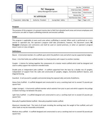
EXCEL UNIVERSAL BEAM TUBE CLAMPUniversal Beam Tube Clamps are designed toallow the user to design and build scaffoldingin any location where there are accessibleapproved I-beams.The clamps attach to the flange of the I-beam andprovide either a clamp connection or a two-cupExcel Vertical (VP2).The clamp and vertical can be rotated in anydirection. This allows for a variety of scaffolddesigns to be built.When used in conjunction with Adjustable PlankBearers and standard Excel components, timeand material needed can be reduced whenbuilding certain scaffolds.Where a scaffold once needed to be built fromthe ground, it can now be built from elevatedbeams or columns.EMSLC-TSM-1001Page 8Revised: 12/31/05
EXCEL UNIVERSAL BEAM TUBE CLAMPTension loading is when the forcetries to pull the clamp away fromthe I-beamSlip loading is when the force tries to slide the clamp along the beam (up or down in the picture above.)Part NumberDescriptionMaximum SlipLoading (lbs.)MaximumTensionLoading (lbs.)WeightGalvanized(lbs.)UBTC-6Universal Beam Tube Clamp 4”-6”1,0004,00014.0UBTC-8Universal Beam Tube Clamp 6”- 8”1,0003,50014.5UBTC-10Universal Beam Tube Clamp 8”-10”1,0003,25015.0UBTC-12Universal Beam Tube Clamp 10”-12”1,0003,00015.5UBCAUniversal Beam Clamp AttachmentN/AN/A1.0UBVAUniversal Beam Clamp Vertical AttachmentN/AN/A4.0When building scaffold using Universal Beam Tube Clamps:1. The scaffold should be designed for light-duty use and deck loading must not exceed 25 lbs/sq ft.2. The maximum horizontal used for the cantilever must not exceed 5 ft.3. See pages 16, 17 and 18 of the Excel Standard Technical Manual (Diagonal Brace used as a Side Bracket) for bracingthat must be followed when building a cantilevered scaffold.4. Each scaffold will require a minimum of six points of attachment.5. Multiple clamps should be used to reduce the loading when building any scaffold. Standard beam clamps should beused as backup clamps (to prevent slip) when a scaffold is installed in high vibration areas or for extendedperiods of time.EMSLC-TSM-1001Page 9Revised: 12/31/05
VERTICAL LEG HANGING BRACKET(VLHB)Part NumberDescriptionMaximumAllowableLoad (lbs.)GalvanizedWeightVLHBVertical Leg Hanging Bracket7,50015Note:1. The Vertical Leg Hanger Bracket allows the user to either hang a scaffold leg from the bottom of the bracket, or extend thescaffold up using the built in coupling pin.2. When suspending a scaffolds VLC shall be used, and the load of the scaffold shall also be taken into consideration whendesigning the scaffold.3. Both the bottom and top bracket should always be installed when using the VLHB.4. VLHB spaces are used to fit beams that have a larger top flange, and come in various sizes.Clamp bolt tension greatly affects the slip loading.Clamp bolts should be tightened between 40 and 65 ft-lbs. Over tightening could damage the threads, bolt or item the clampis attached to. Under tightening could result in clamps slipping at lower than rated loads. CAUTION There is a pinch point located where the beam sides are located on the clamp EMSLC-TSM-1001Page 10Revised: 12/31/05
LIFTING AND MOVINGEXCEL MODULAR SCAFFOLDThe following components are provided to enable fully-assembled Excel Modular Scaffolds to be lifted and moved. Thisenables a section of scaffold to be assembled in a low hazard area and moved into a more dangerous or high hazard area,thereby reducing employee exposures in those areasThe Lifting Device (LD1) attachesto the top of the vertical post. It isdesigned to accept a shackle forsling/cable attachment.LD1 Lifting DeviceThe VLC and VPC aredesigned to provideadded strength to thevertical post connection.Either the VLC or VPCmust be installed on allvertical posts at the pinconnection before liftingthe scaffold.VPC Vertical Leg ConnectorVLC Vertical Locking ClampPart NumberDescriptionMaximum SupportedLoad (lbs.)GalvanizedWeightLD1Lifting Device2,4009.0VLCVertical Leg Connector7,5007.0VPCVertical Locking Clamp2,4009.5The snap button must be fully engaged in both ends of the vertical post connections.Notes:1. All OSHA and plant safety regulations governing rigging and material handling must be followed.2. All loose material must be removed from the scaffold before it is lifted.3. Spreader beams must be used so that the lifting load on all vertical posts is applied in ant upward direction.4. The scaffold must be properly braced to prevent deformation during movement.5. Scaffold weight loads must be calculated to prevent the overloading of any scaffold or lifting component.6. All scaffold components, (deck boards, etc.) must be secured to the scaffold.Clamp bolts should be tightened between 40 and 65 ft-lbs. Over tightening could damage the threads, bolt or itemthe clamp is attached to.All material must be inspected prior to use! See section R of the Standard Component TechnicalManual for inspection guidelines.EMSLC-TSM-1001Page 11Revised: 12/31/05
EXCEL MODULAR SKID PANS (SKID 8-10)Skid pans are used to move scaffold material from a ground level closer to the location the material is required. Thismay be a higher elevation or across obstructions, such as fences, roads, streams, etc.Skid pans come in many different sizes and shapes depending on the intended use. The following guidelines must befollowed regardless of the type of skid pan used.1) All skid pans, cables, shackles and associated lifting equipment must be thoroughly inspected by the designatedperson when first delivered to the jobsite. The inspection must meet the requirements as defined in ASME B30.20-1-3.a) A visual inspection must be performed by a qualified person making records of the apparent externalcondition to provide the basis for a continuing evaluation.b) The inspection must be documented, dated and signed by the person performing the inspection.2) For all equipment inspect:a) Structural members for deformation, cracks or excessive wear.b) Loose or missing guard, fasteners, covers, stops or name plates.c) All functional operating mechanisms for mis-adjustments interfering with operation.d) D eformation—Any bending or twisting exceeding 10 degrees (or as recommended by the manufacturer)from the normal plane.e) T hroat opening—Any distortion causing an increase in the throat opening exceeding 15% (or asrecommended by the manufacturer)f) Wear—Any wear exceeding 10% (or as recommended by the manufacturer) of the original sectiondimensions.3) Visual examinations shall be performed weekly (or more frequently if recommended by the designated person),while the equipment is in service. NO records required.4) A documented thorough inspection shall be performed any time there is reason to believe part of the liftingequipment may have been damaged during use.5) A skid pan shall not be used if it does not contain a label plate that lists the manufacturer, serial number and therated load.Part NumberDescriptionBottomLengthFull LengthEmpty WeightGalvanized(lbs)MaximumAllowable TotalLoad (lbs.)Skid-88’ Long Skid Pan6 ft.8 ft.9003,000Skid-1010’ Long Skid Pan8 ft.10 ft.10503,000Maximum allowable loads shown include the weight of the skid pan & pans content.When not in use the Skid Pan and all associated lifting components shall be stored in such a way to protect the life ofthe equipment.EMSLC-TSM-1001Page 12Revised: 03/03/13
ADJUSTABLE TUBE & CLAMP ADAPTER(ATCA)The Adjustable Tube & Clamp Adapter is designed to allowthe elevation of a board deck to be changed or so that thetop portion of a scaffold can be aligned with a scaffold builton a separate structure.This allows the vertical cups of one scaffold to be alignedwith another scaffold built at a different elevation.The ATCA may be placed on top of an existing ExcelModular Scaffold or Tube & Clamp scaffold.There must be a wrap of horizontals (either Excel Modularor Tube & Clamp) attached to the verticals above andbelow the ATCA.Part NumberDescriptionGalvanizedWeight (lbs.)Maximum AllowableLoad (lbs.)@ 12” ExtensionATCAAdjustable Tube & Clamp Adapter125,000Note:1. There must always be a minimum of 6” of screw inside the upper and lower vertical.2. Only one ATCA may be used in any run of verticals.3. Before use inspect the ATCA assembly to insure that there are no cracks in the wing nuts and verify that the threetack welds are visibly in place.4. The maximum spacing between the nuts is 12 inches.All material must be inspected prior to use! See section R of the Standard Component TechnicalManual for inspection guidelines.EMSLC-TSM-1001Page 13Revised: 3/27/13
EXCEL MODULAR ROOF ADAPTER (RA)Note: Support must be added at point “A”or Point “B” to prevent theverticals from spreading apart.Part NumberDescriptionMaximumAllowable Load FGalvanizedWeight (lbs.)RARoof Adapter1,0005.8Note:When covering scaffold with plastic, tarps or other types of solid material, the user must consider all windand or snow loading. Excel recommends that all users consult with an Excel engineer to ensure properbracing for the maximum expected wind or snow loads. CAUTION: There is a pinch point located where the beam sides are located on the clamp. Workers should not pass vertical legs with the roof adapters installed, they should be passed separately.All material must be inspected prior to use! See section R of the Standard ComponentTechnical Manual for inspection guidelines.EMSLC-TSM-1001Page 14Revised: 03/27/13
EXCEL MODULAR COUNTER WEIGHTBASE PLATE (CWBP)Counter Weight Base Plates are designed to provide handrailprotection for floor openings or other hazards where it is necessaryto prevent access. Counter Weight Base Plates do not require anytie offs to permanent plant components.Base Plates are rubber backed to prevent damage to the floorsurface. Base Plates can be installed on roof tops that requireworking near a roof edge. Base Plates can be used to help stabilizea scaffold where counter weights are requested (i.e. lunch tents,outrigger scaffolds, etc.).All guardrails must have a handrail and mid-rail and should beinstalled at the same elevations as required by scaffold handrailsand mid-rails in accordance with CFR 29 1926 subpart “L”.Single guardrail sets must have aminimum of four (4) Counter WeightBase Plates installed and two (2)outriggers.Multiple guardrail sets must have a minimum of one (1) Counter Weight Base Plate for each five (5) feet of guardrail.Setup required for multiple guardrail sets: Part “A” sizes six (6) to ten (10) feet in length.Setup required for multiple guardrail sets: Part “B” sizes up to five (5) feet in length.EMSLC-TSM-1001Page 15Revised: 03/27/13
EXCEL MODULAR COUNTER WEIGHTBASE PLATEPart NumberDescriptionGalvanizedWeight (lbs.)CWBPCounter Weight Base Plate80.0GuardrailPart A (ft.)Minimum Size of SupportBar B (ft.)10797867666554535Safety Notes:1. Guard rail system (GRS) should always be installed and signed-off on by a competent person before pulling anyfloor plugs or removing deck grating.2. When installing GRS on roof tops, personal fall protection must be used until the GRS has been completelyinstalled.3. Leading edge GRS base plates must be set back a minimum of six (6) feet of the opening being protected.4. GRS must be inspected by the craft performing the work prior to each shift to ensure it has not been modified.5. GRS base plates weigh 80 pounds and should be handled by two or more persons, or the proper liftingequipment.6. GRS should never be used on dirt, gravel or other surfaces that could allow the base plate to sink or slide.EMSLC-TSM-1001Page 16Revised: 08/01/06
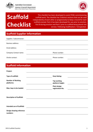
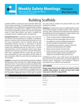
EXCEL MODULAR TROLLEY SYSTEMThe pulley assembly may be placed anywhere on the truss.The maximum load capacity for a vertical lift is 3,000 lbs.The Trolley system is not designed for side loading and should never be used to pick up anyload not aligned with the trolley.Horizontal members shall be placed at a maximum of every 12 cups (69 inches apart).Multiple hoists may be used for longer loads, as long as the total weight of 3,000 lbs. is not exceeded, or isdesigned by an Excel engineer.EMSLC-TSM-1001Page 17Revised: 08/01/06
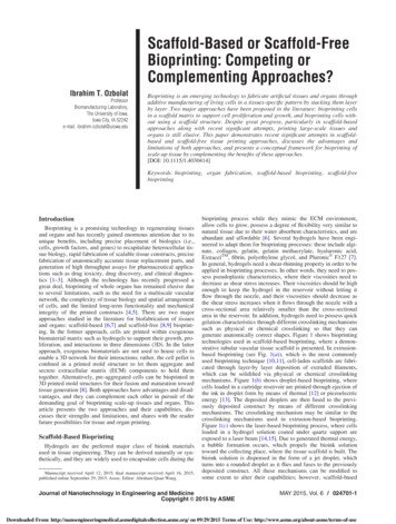
EXCEL MODULAR TROLLEY SYSTEMThe trolley hangs 27 to 29 inches belowthe top of the truss.For greater load control multiple I-beams maybe grouped on a single truss.Loads up to 6,000 lbs. can be lifted by twoTrolleys under the following conditions:1) T he load must be evenly distributed to eachtrolley.2) T he following Trusses meet the 6,000 lb.capacity requirement.TR-4, TR-5, TR-8, TR-9, TR10, TR12See Note 1 for other trusses.Beam Trolley Splicing allowslong runs of beams to beused to move loads greaterdistances.Note #1:Loads over 3,000 lbs. can be supporte
Trolley System Components** H-6 10/14/2009 Shoring System** AD-1 to AD-2 & AE-1 12/31/2005 Aluminum Ladders** J-4 10/14/2009 SRL Adapter** T-5 1/15/2012 . scaffold components should not be conducted without a formal test plan approved by the manufacturer. 8. All end-users must be trained in the proper use of Excel Modular Scaffold.