Transcription
Plettac conturModular systemGuide for erection and useVersion: December 2011ALTRAD Plettac asscoGmbH Daimlerstr. 258840 Plettenberg
Plettac contur Modular SystemGuide for erection and usePage 1Table of Contents1.1.11.21.31.41.5GeneralPreliminary notesTruss systemObligatory testing and documentationSafety guidelines for scaffold usersAssembling the modular connection2.2.12.22.3Plettac contur as façade scaffoldingStandard set-upConstruction of the first scaffold sectionConstruction of the additional scaffold sections2.4Construction of additional 4.6GeneralScaffolding assemblySafety measures during constructionInstallation guard railsPersonal protective equipment to prevent fallsAnchoringFeeding the pin forces into the anchorageProof loads for anchorages2.52.5.12.5.22.5.3Set-up options and installation of additional componentsGeneralSet-up optionsInstalling additional components2.6Dismantling the Plettac contur modular systemas façade scaffoldingUse of the Plettac contur modular systemas façade scaffoldingInspection log for work and safety scaffoldingCheck list for scaffold users to checkof work and safety scaffolds2.72.82.9December 20113445689121516212425282930303739394042
Page 2Plettac contur Modular SystemGuide for erection and useDecember 2011
Plettac contur Modular SystemGuide for erection and usePage 31. General1.1 Preliminary notesWith regard to the following guide for the erection and use of thePlettac contur modular system, please note that as a basicrequirement, scaffolding must only be assembled, dismantled andmodified under the supervision of a qualified person and byprofessionally qualified staff who have received appropriateinstructions for performing this work. In addition, we also refer to therequirements of the German Industrial Safety Ordinance (BetrSichV).Within the scope of the following guide for erection and use, weprovide the assembler and user with options based on our riskassessment in order to take the requirements of the BetrSichV intoconsideration in each respective assembly situation.Construction of thePlettac conturmodular systemunder the supervisionof a qualifiedThe technical details listed in these guide for erection and use, whichshould be of use to the assembler and user for compliance with therequirements of the BetrSichV, are not mandatory requirements forthese workers. The assembler and user should comply with thenecessary measures according to their best judgement based on therisk assessment they are required to perform in accordance with therequirements of the BetrSichV. The special features of each individualsituation should be taken into consideration.individual byEssentially, however, is that attention is given to the following guide forerection and use. It should be noted that all information, in particularwith regard to stability, is only applicable when using original Plettacassco components marked with the approval Z-8.22-843. Theincorporation of components from other manufacturers may result insafety defects and insufficient stability.into account usingA plan for the assembly, modification and dismantling (assemblyinstructions) is to be prepared by the scaffolding contractor responsiblefor the construction according to the complexity of the work oralternatively, this contractor should arrange for such a plan to beprepared by a specific qualified individual. These Guide for erectionand use, supplemented by details for the specific scaffolding type, canbe used for this purpose.This guide for erection and use must be provided to the site supervisorand relevant employees.The pictograms used in the notes in the margins have the followingmeanings:InformationImportant noteor warningDecember 2011Fall hazardprofessionally qualifiedstaff on the basis ofthe hazardassessmenttaking these A&Vcomponents markedwith the approvalZ-8.22-843
Page 4Plettac contur Modular SystemGuide for erection and use1.2 Scaffolding systemThe Plettac contur modular system consists of hot-dip galvanized steel uprightsand ledgers. The vertical standards have welded perforated discs at intervalsof 50 cm, while the ledgers have connecting heads at their ends which arekeyed to the perforated discs. The field lengths and widths are 0.75 m, 1.00 m,1.50 m, 2,00 m, 2.50 m and 3.00 m. Shorter transoms in the width of theSL-frame scaffolding (0.74 m {SL70} and 1.06 m {SL100}) are also available.The deck level is 2.00 m, whereby vertical distance requirementsheight class H1 according to DIN EN 12811 -1 are met.The vertical standards are hitched using a pipe connector attached to the head.The scaffold is braced using vertical and horizontal diagonals.The manufacture and labelling of the components is regulated by the generalbuilding inspectorate approval Z-8.22-843.1.3 Obligatory testing and documentation"Accessforbidden"The Plettac contur modular system must be inspected after everyassembly by the assembler and before every use by the user,whereby the inspection must be performed by competent individuals.The inspection must be documented. If certain areas of thescaffolding is not safe for use, in particular during assembly,modification or dismantling, these areas are to be marked with an"Access prohibited" sign. The area should also be blocked off to makeclear that the scaffolding is not ready for use and that no one shouldaccess the area for this reason.After completion and inspection, the scaffolding should be marked.The sign should be displayed in a clearly visible location and shouldcontain the following information in addition to general safetyinstructions:·Work scaffolding according to EN 12811 -1 and / or DIN 4420-1The Plettac conturmodular systemshould be inspectedbefore each use.·Width class W06 and load class: 3·Evenly distributed load: max. 2.0 kN/m²·Date of inspectionThis inspectionmust bedocumented.·Scaffolding construction firm .·Postcode City · Tel. .The results of the inspection are to be documented in the form of aninspection record and stored for a reasonable period, usually for threemonths after the scaffolding has been dismantled.December 2011
Plettac contur Modular SystemGuide for erection and usePage 51.4 Safety guidelines for scaffold users·Each user must inspect the Plettac contur modular system before usefor obvious defects (see paragraph 1.3).·Each user is responsible for the correct use of the scaffold andmaintenance of its operational safety. The BG information "Instructionsfor the use of work and safety scaffolds" (BGI 663) is recommended asa guide for this purpose.·Any defects caused by bad weather or as a result of construction worketc. during the period of use are to be immediately reported to thescaffolding contractor.·The Plettac contur modular system must only be accessed and vacatedusing an appropriate entry or steps. Climbing and jumping is prohibited.·The scaffold user should ensure that unauthorised individuals cannotgain access.·The Plettac contur modular system must not be accessed by individualsunder the influence of alcohol or drugs.·Jumping off and throwing objects from scaffold platforms is prohibited.·Flaps in trapdoor covers must be kept closed during work on thescaffold level.·Work on several consecutive levels at the same time is to be avoided.There is an increased risk of accidents due to falling objects.·Leaning over the side rails is prohibited.·The Plettac contur modular system can be loaded with a maximumpayload of p 2.0 kN / m² in one location in the standard set-up as afaçade scaffold in accordance with the approval. Larger area loads arepossible but must be verified separately. The scaffolding or sections ofthe scaffolding may collapse if overloaded.·······When used as a safety or roof safety scaffold, no materials should bestored and no equipment should be placed in the fall area. This wouldincrease the risk of injury to falling persons.The scaffold user is not permitted to expand the side rail sections orscaffold brackets or make any changes to the foundation set-up. Theuser should also ensure that others participating in the construction workdo not make any such changes. Missing scaffold brackets and insufficientfoundations for the scaffold uprights may result in the collapse of theentire scaffold structure. If changes to the scaffold are required during theconstruction process, these changes must be performed by the scaffoldcontractor.The scaffold user must not subsequently install any elevators, debrisslides or cladding, such as nets and tarpaulins. This also applies toadvertising banners.As a basic principle, the Plettac contur modular system must only bemodified by the scaffolding contractor.December 2011Climbing on andjumping from thescaffold involvesan increased riskof accidents!When overloaded,the Plettac conturmodular systemmay collapse!Following theexpansion ofcomponents, thefaçade scaffoldingmay collapse andpeople could fall!Only thescaffoldingcontractor isauthorised to makemodifications to thePlettac conturmodular system!
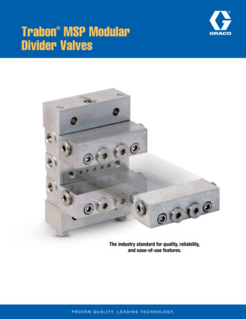
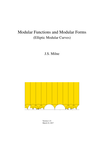
Page 6Plettac contur Modular SystemGuide for erection and use1.5 Assembling the modular connectionThe wedge lock principle was selected as the modular connection(ledger - vertical standard). Even when the wedge is only looselyinserted, this gives the scaffold stability. When the wedge is securedby hitting it with a hammer, creating a frictional connection. The upperand lower bearing surface of the head piece is pressed against thevertical standards (Fig.1), creating an extremely rigid connection.Fig. 1: Wedge lock connectionThe ledger head is pushed laterally over the perforated disc. Thewedge is firmly fixed in a horizontal position to the ledger pipe (Fig. 2)by a rivet at the tip.Fig. 2: Insertion of the headpieceDecember 2011
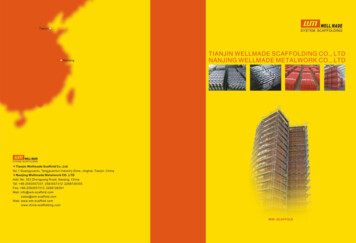
Plettac contur Modular SystemGuide for erection and usePage 7By lifting and inserting the wedge, the ledger is locked and is thenfirmly connected firmly to the vertical standards by applying a 500 ghammer until they click into place (Fig. 3).Fig. 3: Wedging the headpieceThe perforated disc (Fig. 4) has four small holes which are offset by90 . The ledgers are attached here if a right angle is required for thebasic configuration. This then forms automatically once wedged intoplace.Fig. 4: RosetteLonger holes are located between the small holes which can be usedto create variable ledger connections of 15 . This allows theconstruction of basic configurations which do not have a 90 grid.The recesses on the outer edge of the perforated disk not only formthe special "contur" of the scaffold connection, but also reduceweight and make the uprights easier to stack on the palette. Theresulting non-circular shape prevents them from rolling away on asloping surface.December 2011Immediatelyhammer in thewedges afterinstallation of thecomponents using a500 g hammeruntil they clickinto place!
Page 8Plettac contur Modular SystemGuide for erection and use2. Plettac contur as façade scaffolding2.1 Standard set-upWhen installing thePlettac contur modularsystem as façadescaffolding, thefollowing is applicable:Regulation inapproval notificationZ-8.22-843Load class 3Payloads:Cl 3 2.0 kN / m²Max standing height 24 m asstandard set-upin the event ofdeviations fromthe standardset-up, additionaldocumentedThe assembly and dismantling of the standard set-up as façadescaffolding in accordance with approval Z-8.22-843 is described inChapter 2. The Plettac contur modular system can be used accordingto this standard set-up for work scaffolds of load class 3, in addition tosafety scaffolds and roof safety scaffolds.The scaffold components regulated in the approval are listed inChapter 8. The scaffolding platforms which can be used for safetyscaffolds and roof safety scaffolds are listed in Table 1.The maximum height of the standard set-up is 24 m plus jackextension length.If the Plettac contur modular system is used for scaffolds whichdeviate from this standard set-up as a façade scaffold, these scaffoldsmust be assessed and, if necessary, calculated on the basis ofconstruction law, according to the technical building regulations andthe provisions of general building inspectorate approval Z-8.22-843.This guide for erection and use are only applicable in connection withthe use of original Plettac assco components that are marked inaccordance with approval Z-8.22-843. All scaffolding components areto be visually inspected before installation to ensure they are free ofdefects.evidence ofconformity isrequired.Damaged scaffold components must not be used.The Plettac contur modular system is to be set up as façade scaffoldfollowing the order of the sections below.December 2011
Plettac contur Modular SystemGuide for erection and use2.2Construction of the first scaffold section2.2.1 Base of the scaffoldThe base of the scaffold consists of base jacks, starting collars andhorizontal ledgers parallel and transverse to the façade (Fig. 5).Starting collars with base jacks(Annex B, pages 17 and 18)Load-distributing substructureFig. 5: Base of the scaffoldThe starting collars are first placed on the base jacks and connectedto the horizontal ledgers according to Fig. 5. Insert the wedges looselyand align the braces horizontally using a spirit level. The wedgesshould not be locked into place until this step is complete. The exactbase of the scaffold has now been created. Due to the low weight, thebase of the scaffold can be moved easily and placed into the correctposition against the façade. A distance should be selected whichensures that the inner edge of the decks to be incorporated at a laterdate are no further than 30 cm away from the façade.2.2.2 Load-distributing substructureThe Plettac contur modular system must only be installed onsufficiently load-bearing ground. If the substructure is not sufficientlyload-bearing, load-distributing substructures should be used, e.g. ascaffolding brace as shown in Fig. 5. If appropriate, one-piece padscan be placed under each of the uprights (Fig. 6).Wedge with slopinggroundFig. 6: Load-distributing substructure (one-piece)In the case of sloping ground, the substructures should be secured tostop them from sliding. If possible, the ground should be flattenedaccordingly so that a horizontal base is available.December 2011Page 9
Plettac contur Modular SystemGuide for erection and usePage 102.2.3 Base jacksBase pads must liecompletely flat.The possible drill-finish lengths w (UK base plate to OK spindle nut)are as follows for the scaffold uprights listed in the approvalnotification, Annex B, page 18:wThe jacks maybend otherwise!An adjustable base jacks is to be installed under each modularupright (Fig. 5). Base jacks should usually be drill-finished up to 25cm.correctincorrectOverall length L1(cm)406080Drill-finish length w(cm)25.545.560.5The thread of the spindles is destroyed at the corresponding locationsso that they can no longer be unscrewed.2.2.4 Vertical uprightsThe vertical uprights are inserted into the starting collars. 4.0 m longuprights should be inserted on the façade side and 3.0 m uprights onthe outer side (see Fig. 16). A further ledger transverse to the façademay be required 50 cm above the base ledger (see the set-upvariants).The length of the lower transverse ledgers should be selected on thebasis of the planned covering system for the façade scaffolding. In thecase of SL decks, ledgers with a system length of 74 cm should beused, or a system length of 75 cm in the case of round pipe supports.4.0 mTip: The net length between the head tips is 5 cm lower in eachcase.*) This horizontal ledgeris only used to stabilisethe first scaffoldm3.0transomssection! This is notrequired for the furtherconstruction of the(Annex B,pages 24 or 25))*standard set-up.additionaltransverseledger (ifnecessaryFig. 7: Installation of vertical uprightsDecember 2011Fig. 8: Installation of decks
Plettac contur Modular SystemGuide for erection and usePage 112.2.5 Installation of decksOnly those decks listed in Table 1 should be used.Decks for SL supportThe transoms with a system length of 74 cm should be used toaccommodate the SL decks (Annex B, page 25). The holes located onthe head pieces of the decks are pushed through the star ledgers ofthe transoms. The decks then form a horizontal rigid disc and stabilizethe scaffolding. Two 32 cm-wide steel decks or an aluminium accessplatform may be required for each field with a width of 74 cm. Thedeck retainer according to Annex B, page 29 is to be installed acrossthe transverse joint to secure the decks. If this is not possible, thedecks should be secured to prevent lifting using other appropriatemeasures.All scaffold levelsmust be fullyconstructed! Levelswith only a 32 cmwide covering willnot give thescaffold asufficiently securestructure!Decks for pipe supportThe horizontal ledgers with a system length of 75 cm (Annex B, page24) should be used to accommodate the pipe support decks. Thebase boards are laid across the ledgers using the claws and arepushed into the correct position. The anti-lift latches click into placeautomatically (check). Two 32 cm-wide steel decks or a 64 cm widealuminium access platforms must also be installed for each field.Table 1: Deck elements for the standard set-upDescriptionApprovalZ-8.22-843,(Annex B,PageUsein catch andRoof safetyScaffoldingSteel deck 32SL support38permittedSteel deck 32Pipe support41permitted59Aluminium accessplatformwith plywood flooringSL supportAluminium accessplatformwith aluminiumcoveringSL supportAluminium accessplatformwith aluminiumcoveringPipe supportField lengthL (m)Load class(max) 2.002.503.00 503.004365permitted 2.503.0043In the case of thedecks for pipesupports, it shouldbe checked whetherthe anti-liftinglatches are closedfollowinginstallation. Ifnecessary, theymay need to beclosed by hand. Itmust be ensuresthat the safetylevels can alwaysmove easily insidethe bracket (seealso Section 3.3.1)For detailed information about the carrying capacity of the decks, See Table 7 inChapter 6.6.December 2011
Plettac contur Modular SystemPage 12Guide for erection and use2.3Construction of the additional scaffold sections2.3.1 Normal areaThe construction of the additional scaffold sections is performed asdescribed in the previous section. The longitudinal ledgers at the basepoints are to be arranged consecutively (Fig. 9). An aluminium accessplatform should be installed in the climbing area instead of the steeldecks. Steel deck plates should be placed on the lower cross ledgersto provide proper support for the leads.These horizontalledgers can beremoved afterinstallation of theside rails in thedeck levels 2 m!Fig. 9: The first scaffold level2.3.2 Uneven terrainIn the case of sloping terrain and height differences or if specificlocation heights are required, correspondingly longer vertical shaftsshould be installed. These should be braced longitudinally andtransversely using ledgers, along with additional diagonal ledgers ifrequired.Fig. 10: Height compensation on uneven terrainDecember 2011
Plettac contur Modular SystemGuide for erection and usePage 132.3.3 Corner formationA range of corner configurations can be created with the Plettaccontur modular system. A differentiation must be made between theinner and outer corners. It is important that the chosen constructionallows consoles to be attached to the façade side of the scaffoldingand that the three-part side rails can be installed on the outer side ofthe scaffolding. Fig. 11 shows the best construction design for aninner corner, Variant A with no consoles and variant B with consolesin front of the façade. Variant A can be used for an outer corner in thisway. All variants can be built with either the pipe supports or SLsupports (the pipe supports are shown here).7475SL supportPipe supportPipe support74supportSLVariant ASelect a designwhich allows thethree-part side railsto be correctlyinstalled on theouter side of thescaffolding.75Side rails41417475SL supportPipe supportVariant BPipesupportSlatted floor(Annex B, page 57)or horizontal ledgerssupportSLConsoles 41(Annex B, pages 50 or 52)41417574Side railsCorner coveringFig. 11: Scaffolding the inner cornersDecember 2011The variants showncan be built witheither the pipesupports or SLsupports.
Page 14Plettac contur Modular SystemGuide for erection and useVariant C4175supportSLPipe supportPipe supportSL support747475Select a designwhich allows thethree-part side railsto be correctlyinstalled on theouter side of thescaffolding.supportSLFig. 12 shows different ways of scaffolding an outer corner. VariantsC (without consoles) and D (with consoles in front of the façade) arevariable with regard to the position of abutting scaffolding. Variant E isthe optimum design with the least number of uprights. However, ahorizontal ledger (pipe support) or an SL double ledger is requiredhere as a supporting beam.4141SL supportPipe supportVariant DPipesupport747574Connect using pipes andconnectors or short ledgersSide railsAll variants showncan be built witheither pipe supportsor SL supports.7541Slatted floor(Annex B, page 57)or horizontal ledgersSide railsConnect using pipes andconnectors or short ledgersVariant EHorizontal ledgers (Annex B, page 24) for pipesupports or double ledgers for SL supports (Annex B,page 81)Side railsFig. 12: Scaffolding the outer cornerDecember 2011
Plettac contur Modular SystemGuide for erection and use2.4Page 15Construction of additional platforms12.4.1 GeneralDuring the assembly, modification and dismantling of the other layersof the modular system Plettac Contur, there may be a risk of falling.The scaffolding work must be performed in such a way that the risk offalling is avoided or the remaining risk is kept as low as possible. Thecontractor (scaffold installer) must establish suitable for individualcases or for the respective activities to avoid or minimise risks on thebasis of their risk assessment.The measures are to be selected in consideration of the actualexisting risk, usefulness and practical possibilities based on thefollowing conditions: Risk of falling whenassembling,modifying anddismantling thescaffolding!Qualifications of the staff,Nature and duration of the activity in the hazardous area,Potential fall height,Type of surface which staff could fall ontoNature of the workplace and its accessTechnical and personnel measures can be applied for the assembly,modification and dismantling of the Plettac contur modular system.Possible measures to avoid risks can, for example, include the use of installation guard rails ISR)the use of personal protective gear to prevent falls (PPE toprevent falling)orbe a combination of the two.The use of ISR or PPE to prevent falling can be waived in individualcases if ISR and PPE to prevent falling do not provide sufficientprotection or cannot be used due to the structural and frameworkspecific circumstances.The use of ISR or PPE to prevent falling can only be waived if the work is performed by qualified and physically fitindividuals.the employer has issued special instructions for thejustified exceptional case andthe precipitous edge is clearly visible for the individual.Measures to protect against falls are not required if the work andaccess areas are no more than 0.30 m away from other load-bearingand sufficiently large areas.December 2011Measures toprevent the riskof falling shouldbe identified in arisk assessment!
Page 16Plettac contur Modular SystemGuide for erection and useTemporary tilt safety device on the first scaffold levelWhen building the scaffold, there may be a danger of tipping on thefirst scaffold level where the vertical transportation takes place. Thiscan be prevented with e.g. temporary braces or anchors at theheight of the decks (2m).Danger of tilting onthe first scaffoldlevel!2.4.2Scaffolding assembly2.4.2.1 Vertical transportation of scaffolding partsBuilder's hoists should be used during assembly and dismantling for scaffoldswith a standing height of over 8 m over the erection area. Hand-operatedpulley hoists can also be used as a builder's hoist.However, no builder's hoist is required if the standing height is no more than14 m and the length of the scaffold does not extend more than 10 m.Guardrails and handrails must be available in scaffold sections were verticaltransportation needs to be performed by hand. At least one employee must beon each scaffolding platform for this manual transportation (Fig. 13 and 14).Fig. 13: Hand-transporting scaffold componentsDecember 2011
Plettac contur Modular SystemGuide for erection and usePage 172.4.2.2 Installation of vertical uprights and horizontal ledgersDepending on the level, the uprights on the outer side of the top levelare either 1 m or 3 m apart (see Fig. 16). As an initial measure,horizontal ledgers are installed as side rails at a height of 1 m alongthe entire scaffold and at the ends. The uprights ending here on theside of the façade (Fig. 14) and / or the outer uprights overhangingby 1 m according to the requirements for the planned scaffold heightare then extended and the transoms are installed at a height of 2 m.(Fig. 14).There is anincreased risk offalling when leavingthe protectedhorizontal ledgerarea!Fig. 14: Installation of vertical uprightsDecember 2011
Page 18Plettac contur Modular SystemGuide for erection and useIn the next step, horizontal ledgers should be mounted as knee rails ata height of 50 cm. Together with the side rails, this stabilises thescaffolding parallel to the façade, so they must both be installed beforeleaving the construction site up to the highest level completed at thispoint. Finally, the deck level needs to be fitted with toe boards and thedecks for the next level up should be placed on top.Install knee railsimmediately afterthe side rails. Thishelps to stabilisethe scaffolding!As a rule 4 m uprights should be installed apart from in the foot area(see Fig. 16). Upright lengths for the head area should be selectedaccording to the planned scaffold height.Fig. 15: The second scaffold levelDecember 2011
Plettac contur Modular SystemGuide for erection and usePage 19The upright joints onthe façade side areat the level of thedecks, while at theouter side and theends, they arepositioned 1 m abovethe deck levels. upright joint(decks and siderails are not shownin Fig. 16. nolongitudinal ledgersare required forthe deck levels).Fig. 16: Position of upright jointsDecember 2011
Page 20Plettac contur Modular SystemGuide for erection and use2.4.2.3 Installation of decksThe decks are to be installed in accordance with Section2.2.5.2.4.2.4 Scaffolding accessClose the trapdoorsafter every use!If the trapdoors arenot closed, there isa risk of falling intothe opening!Before descending,check that thetrapdoors below areclosed.If they are notclosed, there is alsoa risk of falling intothe opening!The scaffold access should be installed before starting work on the firstscaffold level (see Section 2.3.1 and Fig. 9). In the case of the Plettaccontur modular system, this is an internal ladder passage consisting ofan aluminium access platform with an integrated ladder. Duringinstallation, the openings should be staggered (Fig. 15) and thetrapdoors should be closed after every use. The trapdoors should neverbe propped up or fixed by folding them back or in any other way. If thetrapdoors are not closed after use, there will be a risk of falling into theopening.2.4.2.5 CrossbeamsCrossbeams (vertical diagonals) are not required in the standard set-up.Only the horizontal ledgers for the side rails are used to reinforce thescaffolding parallel to the façade.2.4.2.6 Finish installing the side railsMissing side rails and toe boards, in addition to the full side rails at theends of the contur scaffolding are to be installed on all scaffold levelswhich are not used for the construction of the scaffold. Doublelongitudinal ledgers are always required at every level, even on levelsnot intended for working operations.The toe boards in the SL set-up are placed with their end fittings againstthe toe board pins in such a way that their upper edges are continuouslyat a height. The longitudinal toe boards are identical to those in the SLframe scaffolding, where the cross-toe boards are on the deck retainerand are therefore only 125 mm high. They can be identified by the words"cross" (Annex B, page 46). The toe board pins are integrated in to thedeck retainer (Annex B, page 29). In special cases, individual toe boardholder (Annex B, page 47) can be installed.The toe boards for pipe supports (Annex B, page 4 8) are on the steeldecks. The fittings are clamped between the wedge and verticalstandards.December 2011
Plettac contur Modular SystemGuide for erection and use2.4.3Page 21Safety measures during construction2.4.3.1 Installation guard railsGeneralThere may be a risk of falling during the ascent to the uppermostscaffold level and subsequent assembly of the uprights and ledgers.It is therefore recommended that the assembly safety railings (ISR)are used for safety in the access area as a security measure for theascent to the uppermost scaffold level. If no uprights running upfrom below are available in the access area, the assembler can holdonto the ISR post. The strut acts as a side rail to attach the firstupright and the horizontal ledger (railing) in the area.RecommendationUse installationguard railings (ISR)use in theaccess area!The installation guard railings are assembled from the levelunderneath before accessing the upper level of the scaffolding. Toreduce risks during assembly of the ISR, complete three-sided siderails are to be installed beforehand.Description of the installation guard railingsThe set-up with lockable posts and telescopic struts is describedhere (see Annex A, pages 138 and 139 of the SL70 approval dated2010).The installation guard railings consist of individu
1.4 Safety guidelines for scaffold users 5 1.5 Assembling the modular connection 6 2. Plettac contur as façade scaffolding 2.1 Standard set-up 8 2.2 Construction of the first scaffold section 9 2.3 Construction of the additional scaffold sections 12 2.4 Construction of additional platforms 2.4.1 General 15