Transcription
Application Note #665Revision CAugust 2019Integrating Infratech Heaters with Lutron Residential SystemsOverviewLutron residential systems are capable of controlling 0–10 V- devices and lighting loads via LMJ-5T-DV-B, LQSE-4T5-120-D,GRX-TVM2, or GRX-TVI-CPN3876. This document describes how to utilize LMJ-5T-DV-B, LQSE-4T5-120-D, GRX-TVM2, orGRX-TVI-CPN3876 to control Infratech heaters.Table of Contents1.0 Controlling Infratech Heaters Using 0-10 V-22.0 LMJ-5T-DV-B Controlling Infratech Heaters in HomeWorks / RadioRA 2 Systems22.1 Installation2.2 Database Design2.2.12.2.22.2.32.2.4244678HomeWorks Load ScheduleAdding an LMJ-5T-DV-B to a HomeWorks SystemAssigning Infratech Heaters to an LMJ-5T-DV-B in a HomeWorks SystemAdding an LMJ-5T-DV-B to a RadioRA 2 System3.0 LQSE-4T5-120-D Controlling Infratech Heaters in a HomeWorks System3.1 Installation3.2 Database Design3.2.1 Load Schedule3.2.2 Adding Equipment3.2.3 Assigning the Infratech Heaters to the Panel4.0 GRX-TVM2 Controlling Infratech Heaters in a HomeWorks System4.1 Installation4.2 Database Design4.2.1 Load Schedule4.2.2 Adding Equipment4.2.3 Assigning the Infratech Heaters to the Panel5.0 G RX-TVI-CPN3876 Controlling Infratech Heaters inHomeWorks, RadioRA 2, or Caséta Wireless Systems5.1 Installation5.2 HomeWorks Database Design5.2.1 HomeWorks Load Schedule5.2.2 Adding Controls5.2.3 Assigning Infratech Heaters to the Neutral Wire Dimmer5.3 A dding a Neutral Wire Dimmer to a RadioRA 2 System forControl of an Infratech Heater via GRX-TVI-CPN38766.0 Setting Trim Levels on Neutral Wire Dimmers6.1 Setting Trim Levels via HomeWorks Software6.2 Setting Trim Levels via RadioRA 2 Software6.3 Setting Trim Levels on a Caséta Wireless Dimmer (PD-10NXD)6.3.1 Setting Low-End Trim6.3.2 Setting High-End Trim6.4 Setting Trim Levels When Using 262730303132323334www.lutron.com/support
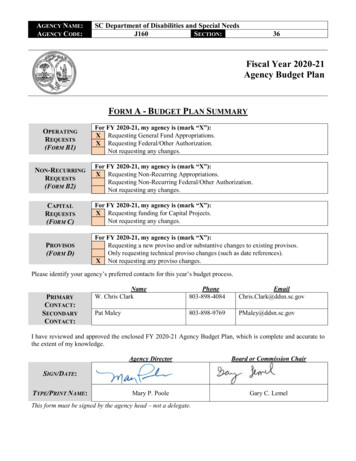
Application Note #6651.0 Controlling Infratech Heaters Using 0–10 VInfratech heaters require a control device to source a 0–10 V- signal. For more information on the ANSI standard forsourcing 0–10 V- controls, refer to Application Note #587 (048587) at www.lutron.com. In order to turn off an Infratechheater, the Lutron control will need to interrupt the 0–10 V- signal using an EPC-1-D manufactured by LVS Controls (notsold by Lutron). An EPC-1-D is required because the relays used to turn on / off 0–10 V- lighting are not rated to controlInfratech heaters.2.0 LMJ-5T-DV-B Controlling Infratech Heaters in HomeWorks / RadioRA 2Systems2.1 InstallationItems needed for this ontrols the 0–10 V- loadEPC-1-DLVS ControlsInterrupts the 0–10 V- signalInfratech relay moduleInfratechInterrupts line voltage to heatersHomeWorks processor or RadioRA 2 main repeaterLutronStores the databaseHomeWorks hybrid repeater (if using a HomeWorksprocessor)LutronCreates Clear Connect wireless signalThe diagram below demonstrates how an LMJ-5T-DV-B needs to be wired to the Infratech system.EPC-1-DNeutral120 / 277 V DistributionpanelWhiteBlack (120 V )HotRedorOrange (277 V )Blue0–10 V- ControlInputsLMJ-5T-DV-BInfratechrelay module0-10 V- ( )0-10 V- ( ) T he neutral wires of the LMJ-5T-DV-B and the EPC-1-D must originate in the same distribution panel. This neutral may onlyreturn loads supplied by the same circuit breaker as the LMJ-5T-DV-B and EPC-1-D (Split/Single Phase and Three Phasesystems: This neutral may not be shared with other circuit breakers). D o not connect both the black and orange wires of the EPC-1-D to the red wire of the LMJ-5T-DV-B. Cap off the unusedwire. This controls the switching portion of the Infratech system and controls the on / off function.Continued on next page.2Customer Assistance — 1.844.LUTRON1
Application Note #6652.0 LMJ-5T-DV-B Controlling Infratech Heaters in HomeWorks / RadioRA 2Systems (continued)2.1 Installation (continued)Important Note: LMJ-5T-DV-B is a wireless device and must be located within 30 ft (9 m) of a repeater. In a HomeWorkssystem, an RF link with a hybrid repeater is required.Wired and RF Configuration (RadioRA 2 and HomeWorks)Repeater*LMJ-5T-DV-BLMJ-5T-DV-B30 ft (9 m)maximum30 ft (9 m)maximumRF link1000 ft (305 m)maximum wirelength per run30 ft (9 m)maximumRF link60 ft (18 m)maximum1000 ft (305 m)maximum wirelength per run* In HomeWorks systems, hybrid repeaters can be used to extend the wireless range. In RadioRA 2 systems, the repeater used caneither be a main repeater (1 required) or auxiliary repeater (up to 4 permitted).Continued on next page.3www.lutron.com/support
Application Note #6652.0 LMJ-5T-DV-B Controlling Infratech Heaters in HomeWorks / RadioRA 2Systems (continued)2.2 Database Design2.2.1 HomeWorks Load ScheduleImportant Note: HomeWorks Designer version 7.0 or higher is required to use LMJ-5T-DV-B.To begin building the load schedule, go to the design tab menu and select loads.Select an area that will contain the Infratech heaters by clicking on that area name in the tree to the left. The selected areawill be highlighted green.In the upper-right corner of the software window, click Edit Fixtures.Continued on next page.4Customer Assistance — 1.844.LUTRON1
Application Note #6652.0 LMJ-5T-DV-B Controlling Infratech Heaters in HomeWorks / RadioRA 2Systems (continued)2.2 Database Design (continued)2.2.1 HomeWorks Load Schedule(continued)The System Fixtures configuration window will appear which allows you to create fixture placeholders for easy placementinto the load schedule. On the Custom tab, create a fixture placeholder for the 0–10 V- devices / loads that will becontrolled by an LMJ-5T-DV-B. There are two options for 0–10 V- loads: LED or Fluorescent. Selecting either LEDor Fluorescent will still control the Infratech heaters even though a lighting load is selected. Choosing either LED orFluorescent changes the trim level that can be set to 1 on the low-end and 99 on the high-end. You may need to showHigh End and Low End by customizing the columns.Click Done to close the System Fixtures window and return to the load schedule for the selected area. Double-click in theFixture field to reveal a drop-down menu with all currently created custom or Ivalo fixture options within the project. SelectInfratech and the software will add a load schedule line item in the selected area for the Infratech heaters in that space.Provide a zone name, zone description, and any other pertinent information. Repeat this process for each Infratech heaterthat is to be controlled by an LMJ-5T-DV-B.Continued on next page.5www.lutron.com/support
Application Note #6652.0 LMJ-5T-DV-B Controlling Infratech Heaters in HomeWorks / RadioRA 2Systems (continued)2.2 Database Design (continued)2.2.2 Adding an LMJ-5T-DV-B to a HomeWorks SystemAdd the LMJ-5T-DV-B that the Infratech heaters will be assigned to. To add the LMJ-5T-DV-B to the database, go to thedesign tab drop down menu and select controls.Select the area in which the LMJ-5T-DV-B is to be physically located using the area tree on the left side of the screen.Use the Controls toolbox to add an LMJ-5T-DV-B to the area. If the LMJ-5T-DV-B is not currently available in the toolbox,click Edit Toolbox and add the LMJ-5T-DV-B to the toolbox.Continued on next page.6Customer Assistance — 1.844.LUTRON1
Application Note #6652.0 LMJ-5T-DV-B Controlling Infratech Heaters in HomeWorks / RadioRA 2Systems (continued)2.2 Database Design (continued)2.2.3 Assigning Infratech Heaters to an LMJ-5T-DV-B in a HomeWorks SystemGo to the design tab drop down menu and select controls. To the right of the LMJ-5T-DV-B image, there will be assignlinks which will show the Assign window when clicked. Click on the Assign link for an LMJ-5T-DV-B controlling an Infratechheater.Find the appropriate Infratech heater to assign to the LMJ-5T-DV-B and click Assign for that zone.The zone will now be assigned to the selected output on the LMJ-5T-DV-B.Important Note: If using the Lutron Connect app, the Infratech heater will appear as a lighting zone.Continued on next page.7www.lutron.com/support
Application Note #6652.0 LMJ-5T-DV-B controlling Infratech Heaters in HomeWorks / RadioRA 2Systems (continued)2.2 Database Design (continued)2.2.4 Adding an LMJ-5T-DV-B to a RadioRA 2 SystemImportant Note: RadioRA 2 Inclusive version 7.5 or higher is required to use LMJ-5T-DV-B.Select the room where the LMJ-5T-DV-B is located. To the right of the selected room, click the “ ” above Click here to adddevice location.To add the LMJ-5T-DV-B that will control the Infratech heater to the database, click on the picture of the LMJ-5T-DV-B underAvailable Devices Dimmers & Switches.Continued on next page.8Customer Assistance — 1.844.LUTRON1
Application Note #6652.0 LMJ-5T-DV-B Controlling Infratech Heaters in HomeWorks / RadioRA 2Systems (continued)2.2 Database Design (continued)2.2.4 Adding an LMJ-5T-DV-B to a RadioRA 2 System(continued)Once the LMJ-5T-DV-B is added, select 0-10V Dimmer from the Device Type drop down menu.On the left side of the screen the model number will change to LMJ-5T-DV-B. Add the Device Location, Zone Name, andLoad Type and click Done. This will add the Infratech heater to the area specified.There are two options for 0–10 V- loads: LED or Fluorescent. Selecting either LED or Fluorescent will still control theInfratech heaters even though a lighting load is selected. Choosing either LED or Fluorescent changes the trim level thatcan be set to 1 on the low-end and 99 on the high-end.Important Note: If using the Lutron Connect app, the Infratech heater will appear as a lighting zone.9Customer Assistance — 1.844.LUTRON1
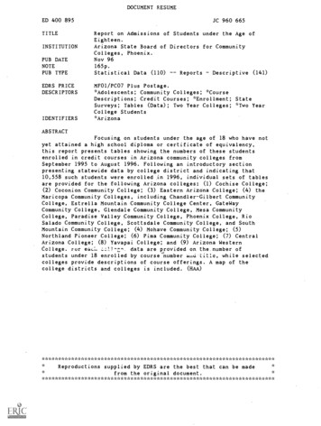
Application Note #6653.0 LQSE-4T5-120-D Controlling Infratech Heaters in a HomeWorks System3.1 InstallationItems needed for this installation:ItemCompanyFunctionEPC-1-DLVS ControlsInterrupts the 0–10 V- signalInfratech relay moduleInfratechInterrupts line voltage to heatersLQSE-4T5-120-DLutronControls the 120 V switching andprovides the 0–10 V- to control load(Infratech heater).HomeWorks SystemLutronStores the databaseThe diagram below demonstrates how a LQSE-4T5-120-D needs to be wired to the Infratech system.0-10 V- ( )HomeWorks QSTa 65 CLQSE-4T5-120-DProg120 V 50 / 60 Hz11120 V DistributionpanelLine/HotGroundOpt32Zn 40-10 V 50 mAZn 3H2lutron.com 1.844.LUTRON1NZn 2Def120 V 5 A eaHZn 1COMMUX4.4 in-lb0.5 N mMUXCOM5 /16 in8 mmInput EntradaEntréeCCI0-10 V- ( )ML34EPC-1-DWhiteNeutralRedBlack (120 V )Orange(277 V )BlueInfratechrelay module0–10 VControlInputs T he neutral wires of the LQSE-4T5-120-D and the EPC-1-D must originate in the same distribution panel. This neutral mayonly return loads supplied by the same circuit breaker as the LQSE-4T5-120-D and EPC-1-D (Split/Single Phase and ThreePhase systems: This neutral may not be shared with other circuit breakers). C onnect the black wire of the EPC-1-D to the output of the LQSE-4T5-120-D. Cap off the orange wire. This controls theswitching portion of the Infratech system and controls the on / off function. Power switching and 0-10 V- must be on the same zone (zone 1 shown). O ne LQSE-4T5-120-D can control up to 4 zones of Infratech heaters using separate EPC-1-D relays and Infratechrelay modules.Continued on next page.10www.lutron.com/support
Application Note #6653.0 LQSE-4T5-120-D Controlling Infratech Heaters in a HomeWorks System(continued)3.2 Database Design3.2.1 Load ScheduleTo begin building the load schedule, go to the design tab menu and select loads.Select an area that will contain the Infratech heaters by clicking on that area name in the tree to the left. The selected areawill be highlighted green.In the upper-right corner of the software window, click Edit Fixtures.Continued on next page.11Customer Assistance — 1.844.LUTRON1
Application Note #6653.0 LQSE-4T5-120-D Controlling Infratech Heaters in a HomeWorks System(continued)3.2 Database Design (continued)3.2.1 Load Schedule(continued)The System Fixtures configuration window will appear which allows you to create fixture placeholders for easy placementinto the load schedule. On the Custom tab, create a fixture placeholder for the 0-10 V- devices / loads that will becontrolled by a LQSE-4T5-120-D. There are two options for 0-10 V- loads: LED or Fluorescent. Selecting either LEDor Fluorescent will still control the Infratech heaters even though a lighting load is selected. Choosing either LED orFluorescent changes the trim level that can be set to 1 on the low-end and 99 on the high-end.Click Done to close the System Fixtures window and return to the load schedule for the selected area. Double-click in theFixture field to reveal a drop-down menu with all currently created custom or Ivalo fixture options within the project. SelectInfratech Heater and the software will add a load schedule line item in the selected area for the Infratech heaters in thatspace.Provide a zone name, zone description, and any other pertinent information. Repeat this process for each Infratech heaterthat is to be controlled by a LQSE-4T5-120-D zone.Continued on next page.12www.lutron.com/support
Application Note #6653.0 LQSE-4T5-120-D Controlling Infratech Heaters in a HomeWorks System(continued)3.2 Database Design (continued)3.2.2 Adding EquipmentNext, add the equipment that the Infratech heaters will be assigned to. In this case, the equipment being added would bethe DIN rail panel. To add the panel to the database, go to the design tab menu and select equipment.Select the area in which the dimming panel is to be physically located using the area tree on the left side of the screen.Use the Equipment toolbox to add a DIN rail device compatible dimming panel to the area. In this case, a PD9-59F-120has been selected. If the dimming panel is not currently available in the toolbox, click Edit Toolbox and add the dimmingpanel to the toolbox.Continued on next page.13Customer Assistance — 1.844.LUTRON1
Application Note #6653.0 LQSE-4T5-120-D Controlling Infratech Heaters in a HomeWorks System(continued)3.2 Database Design (continued)3.2.2 Adding Equipment(continued)Configure the DIN rail panel in the software to match the needs of the application. In the example below, for the QScommunication link, a QS-WLB has been added to position 10. For the Infratech heater, one LQSE-4T5-120-D has beenadded to position 1.Continued on next page.14www.lutron.com/support
Application Note #6653.0 LQSE-4T5-120-D Controlling Infratech Heaters in a HomeWorks System(continued)3.2 Database Design (continued)3.2.3 Assigning the Infratech Heaters to the PanelProceed to the design equipment section of the programming software. To the right of the panel 9 image andparameters, there will be assign links which will show the Assign window when clicked. Click on the Assign link for one ofthe zones that will control an Infratech heater via a LQSE-4T5-120-D.Find the zone to assign within the Assign window and click Assign for that zone.The zone will be assigned to the selected output on the panel. A LQSE-4T5-120-D should appear in the Interface fieldalong with the address of the LQSE-4T5-120-D.15Customer Assistance — 1.844.LUTRON1
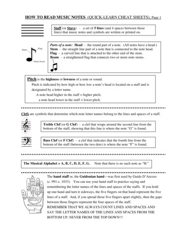
Application Note #6654.0 GRX-TVM2 Controlling Infratech Heaters in a HomeWorks System4.1 InstallationItems needed for this rols the 0–10 V- load. Fits in the 8thRPM location near the top of the panel.EPC-1-DLVS ControlsInterrupts the 0–10 V- signalInfratech relay moduleInfratechInterrupts line voltage to heatersHW-RPM-4U-120LutronControls the 120 V switching of theInfratech heaterHW-TVMKIT-120LutronProvides power to the GRX-TVM2 througha GRX-TVM-ISO2. Also includes DIN railmounting hardware and wire harness.The diagram below demonstrates how an GRX-TVM2 needs to be wired to the Infratech system. An output of a RPMmodule is needed for switching since the GRX-TVM2 controls only 0-10 V-.EPC-1-DNeutral120 / 277 V DistributionpanelWhiteSwitchedHotBlack (120 V )RedLine/HotOrange (277 V )Blue0–10 VControl InputsInfratechrelay moduleGRX-TVM2HW-RPM-4U-120(shown)0-10 V- ( )0-10 V- ( ) T he neutral wires of the HW-RPM-4U and the EPC-1-D must originate in the same distribution panel. This neutral may onlyreturn loads supplied by the same circuit breaker as the HW-RPM-4U or HW-RPM-4A and EPC-1-D (Split/Single Phase andThree Phase systems: This neutral may not be shared with other circuit breakers). C onnect the black wire of the EPC-1-D to the output of the HW-RPM-4U or HW-RPM-4A. Cap off the orange (277 V )wire. This controls the switching portion of the Infratech system and controls the on / off function.Continued on next page.16www.lutron.com/support
Application Note #6654.0 GRX-TVM2 Controlling Infratech Heaters in a HomeWorks System (continued)4.2 Database Design4.2.1 Load ScheduleTo begin building the load schedule, go to the design tab menu and select loads.Select an area that will contain the Infratech heaters by clicking on that area name in the tree to the left. The selected areawill be highlighted green.In the upper-right corner of the software window, click Edit Fixtures.Continued on next page.17Customer Assistance — 1.844.LUTRON1
Application Note #6654.0 GRX-TVM2 Controlling Infratech Heaters in a HomeWorks System (continued)4.2 Database Design (continued)4.2.1 Load Schedule(continued)The System Fixtures configuration window will appear which allows you to create fixture placeholders for easy placementinto the load schedule. On the Custom tab, create a fixture placeholder for the 0-10 V- devices / loads that will becontrolled by a GRX-TVM2. There are two options for 0-10 V- loads: LED or Fluorescent. Selecting either LEDor Fluorescent will still control the Infratech heaters even though a lighting load is selected. Choosing either LED orFluorescent changes the trim level that can be set to 1 on the low-end and 99 on the high-end.Click Done to close the System Fixtures window and return to the load schedule for the selected area. Double-click in theFixture field to reveal a drop-down menu with all currently created custom or Ivalo fixture options within the project. SelectInfratech Heater and the software will add a load schedule line item in the selected area for the Infratech heaters in thatspace.Provide a zone name, zone description, and any other pertinent information. Repeat this process for each Infratech heaterthat is to be controlled by a GRX-TVM2.Continued on next page.18www.lutron.com/support
Application Note #6654.0 GRX-TVM2 Controlling Infratech Heaters in a HomeWorks System (continued)4.2 Database Design (continued)4.2.2 Adding EquipmentNext, add the equipment that the Infratech heaters will be assigned to. In this case, the equipment being added would bethe HWI-PNL-8. To add the panel to the database, go to the design tab menu and select equipment.Select the area in which the dimming panel is to be physically located using the area tree on the left side of the screen.Use the Equipment toolbox to add an HWI-PNL-8 dimming panel to the area. If the dimming panel is not currently availablein the toolbox, click Edit Toolbox and add the dimming panel to the toolbox.Continued on next page.19Customer Assistance — 1.844.LUTRON1
Application Note #6654.0 GRX-TVM2 Controlling Infratech Heaters in a HomeWorks System (continued)4.2 Database Design (continued)4.2.2 Adding Equipment(continued)Configure the HWI-PNL-8 dimming panel in the software to match the needs of the application. A single panel can beconfigured to have a maximum of 32 zones; however, the GRX-TVM2 takes the eighth spot in the panel (top location) andcan control the first 24 loads in the panel.Add the GRX-TVM2 kit to the eighth spot in the panel (top location)Continued on next page.20www.lutron.com/support
Application Note #6654.0 GRX-TVM2 Controlling Infratech Heaters in a HomeWorks System (continued)4.2 Database Design (continued)4.2.3 Assigning the Infratech Heaters to the PanelProceed to the design equipment section of the programming software. To the right of the PNL-8 panel image andparameters, there will be assign links which will show the Assign window when clicked. Click on the Assign link for one ofthe zones that will control an Infratech heater via a GRX-TVM2.Find the zone to assign within the Assign window and click Assign for that zone.The zone will be assigned to the selected output on the panel. A GRX-TVM2 should appear in the Interface field along withthe address of the GRX-TVM2.21Customer Assistance — 1.844.LUTRON1
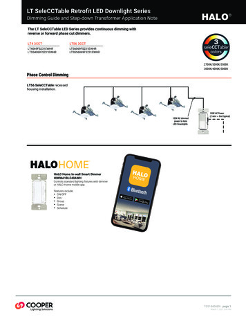
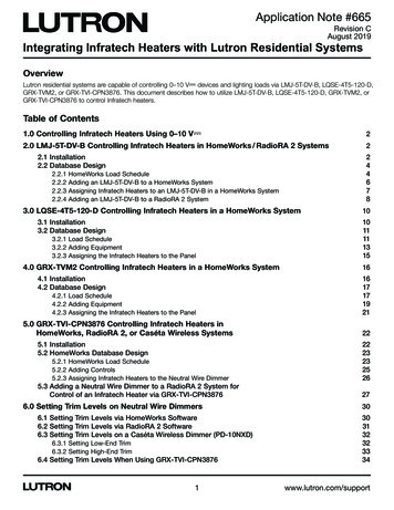
Application Note #6655.0 GRX-TVI-CPN3876 Controlling Infratech Heaters in HomeWorks, RadioRA 2,or Caséta Wireless Systems5.1 InstallationItems needed for this ron0–10 V- source signalEPC-1-DLVS ControlsInterrupts the 0–10 V- signalInfratech relay moduleInfratechInterrupts line voltage to heatersHomeWorks, RadioRA 2, or Caséta Wireless neutralwire dimmerLutronControl point0–10 V-N1SL1 / SH1L1 / H1 100–277 V L2 / H2 100-277 V N2DL2 / DH2The diagram below demonstrates how a GRX-TVI-CPN3876 needs to be wired to the Infratech system and to the neutralwire dimmer.GRX-TVI-CPN3876EPC-1-DWhiteBlack (120 V )Neutral*Redor120 / 277 V DistributionpanelOrange (277 V )Line/Hot**DimmedHot†Blue0–10 VControl Inputs0-10 V- ( )0-10 V- ( )Infratechrelay moduleNeutral wire dimmer‡* Connect to the silver terminal on the dimmer.** Connect to the black terminal on the dimmer.† Connect to the brass terminal on the dimmer. If using a fluorescent dimmer,connect to the orange wire on the dimmer.‡Set the trim of the dimmer accordingly. Refer to section 5.3.3 for trim levels. T he neutral wires of the neutral wire dimmer, GRX-TVI-CPN3876, and the EPC-1-D must originate in the same distributionpanel. This neutral may only return loads supplied by the same circuit breaker as the neutral wire dimmer, GRX-TVI-CPN3876,and EPC-1-D (Split/Single Phase and Three Phase systems: This neutral may not be shared with other circuit breakers.Important Note: In order to utilize this solution, the GRX-TVI-CPN3876 model must be used since the Infratech heatersrequire the control to source the 0–10 V- signal. The GRX-TVI model acts as a sink and follows the IEC standard of0–10 V- control which is not compatible with Infratech heaters.22www.lutron.com/support
Application Note #6655.0 GRX-TVI-CPN3876 Controlling Infratech Heaters in HomeWorks, RadioRA 2,or Caséta Wireless Systems (continued)5.2 HomeWorks Database Design5.2.1 HomeWorks Load ScheduleTo begin building the load schedule, go to the design tab menu and select loads.Select an area that will contain the Infratech heaters by clicking on that area name in the tree to the left. The selected areawill be highlighted green.In the upper-right corner of the software window, click Edit Fixtures.Continued on next page.23Customer Assistance — 1.844.LUTRON1
Application Note #6655.0 GRX-TVI-CPN3876 Controlling Infratech Heaters in HomeWorks, RadioRA 2,or Caséta Wireless Systems (continued)5.2 HomeWorks Database Design (continued)5.2.1 HomeWorks Load Schedule(continued)The System Fixtures configuration window will appear which allows you to create fixture placeholders for easy placementinto the load schedule. On the Custom tab, create a fixture placeholder for the Infratech heaters that will be controlled byan GRX-TVI-CPN3876 and driven by the output of the neutral wire dimmer. There are two options for 0-10 V- loads: LEDor Fluorescent. Select either LED or Fluorescent. The system will still control the Infratech heaters even though a lightingload is selected. Choosing either LED or Fluorescent changes the trim level that can be set to 1 on the low-end and 99on the high-end. You may need to show High End and Low End by customizing the columns. As a best practice, give thefixture a name that will provide a good reminder that the load is tied to the GRX-TVI-CPN3876 controlled by neutral wiredimmer.Important Note: The Lamp Wattage must be entered as “10” or greater when using GRX-TVI-CPN3876.Click Done to close the System Fixtures window and return to the load schedule for the selected area. Double-click in theFixture field to reveal a drop-down menu with all currently created custom or Ivalo fixture options within the project. SelectInfratech Heater and the software will add a load schedule line item in the selected area for the Infratech heaters in thatspace.Provide a zone name, zone description, and any other pertinent information. Repeat this process for each Infratech heaterthat is to be controlled by a neutral wire dimmer driving a GRX-TVI-CPN3876.Continued on next page.24www.lutron.com/support
Application Note #6655.0 GRX-TVI-CPN3876 Controlling Infratech Heaters in HomeWorks, RadioRA 2,or Caséta Wireless Systems (continued)5.2 HomeWorks Database Design (continued)5.2.2 Adding ControlsAdd the equipment that the Infratech heaters will be assigned to. In this case, the equipment being added is the neutral wiredimmer. To add the panel to the database, go to the design tab drop down menu and select controls.Select the area in which the dimming panel is to be physically located using the area tree on the left side of the screen.Use the Controls toolbox to add a neutral wire dimmer to the area. If the dimming panel is not currently available in thetoolbox, click Edit Toolbox and add the dimming panel to the toolbox. Also, uncheck Auto-Create Loads.Continued on next page.25Customer Assistance — 1.844.LUTRON1
Application Note #6655.0 GRX-TVI-CPN3876 Controlling Infratech Heaters in HomeWorks, RadioRA 2,or Caséta Wireless Systems (continued)5.2 HomeWorks Database Design (continued)5.2.3 Assigning Infratech Heaters to the Neutral Wire DimmerRemain in the design controls section of the programming software. To the right of the dimmer image and parameters,there will be assign links which will show the Assign window when clicked. Click on the Assign link for one of the zonesthat will control an Infratech heater via a GRX-TVI-CPN3876.Find the zone to assign within the Assign window and click on Assign for that zoneThe zone will be assigned to the output of the dimmer. A GRX-TVI-CPN3876 should appear in the Interface field.Continued on next page.26www.lutron.com/support
Application Note #6655.0 GRX-TVI-CPN3876 Controlling Infratech Heaters in HomeWorks, RadioRA 2,or Caséta Wireless Systems (continued)5.3 Adding a Neutral Wire Dimmer to a RadioRA 2 System for Control of an Infratech Heatervia GRX-TVI-CPN3876Select the room where the Infratech heaters are located. To the right of the selected room, click the “ ” above Click here toadd device location.Under the Available Devices section, select the dimmer style and then select 0-10V Dimming With Interface in theDevice Type drop down menu. By default, this will add an RRD-10ND with a GRX-TVI.Continued on next page.27Customer Assistance — 1.844.LUTRON1
Application Note #6655.0 GRX-TVI-CPN3876 Controlling Infratech Heaters in HomeWorks, RadioRA 2,or Caséta Wireless Systems (continued)5.3 Adding a Neutral Wire Dimmer to a RadioRA 2 System for Control of an Infratech Heatervia GRX-TVI-CPN3876 (continued)If an RRD-10ND is not the model to be used, click Choose Alternate Model under the Model Number section on theright side of the Add New Device screen.From the drop down list of neutral wire dimmers, select the appropriate dimmer for the application.If using a GRAFIK T dimmer, select the GRAFIK T dimmer image under Available Devices and select either C.L Dimmer orPhase Selectable Dimmer in the Device Type field.Continued on next page.28www.lutron.com/support
Application Note #6655.0 GRX-TVI-CPN3876 Controlling Infratech Heaters in HomeWorks, RadioRA 2,or Caséta Wireless Systems (continued)5.3 Adding a Neutral Wire Dimmer to a RadioRA 2 System for Control of an Infratech Heatervia GRX-TVI-CPN3876 (continued)In the Load Type drop down menu, select any 0–10 V- load. This will auto populate the GRX-TVI under the ModelNumber section.If using a GRAFIK T keypad, select the GRAFIK T keypad image under Available Devices and select either C.L Dimmer orPhase Selectable Dimmer in the Device Type field.*Once added, there will be a “ ” next to the load name29Customer Assistance — 1.844.LUTRON1
Application Note #6656.0 Setting Trim Levels on Neutral Wire Dimmers6.1 Setting Trim Levels via HomeWorks SoftwareTo begin setting the trim levels, go to the design tab menu and select loads.Select an area that will contain the Infratech heaters by clicking on that area name in the tree to the left. The selected areawill be highlighted green.In the upper-right corner of the software window, click Edit Fixtures.The System Fixtures configuration window will appear which allows you to create fixture placeholders for easy placementinto the load schedule. On the Custom tab, create a fixture placeholder for the Infratech heaters by selecting either LED orFluorescent. Choosing either LED or Fluorescent changes the trim level that can be set based on the dimmer being used.You may need to show High End and Low End by customizing the columns. When using a neutral wire dimmer withGRX-TVI-CPN3876, refer to Section 6.4 for trim level settings.Continued on next page.30www.lutron.com/support
Application Note #6656.0 Setting Trim Levels on Neutral Wire Dimmers (continued)6.2 Setting Trim Levels via RadioRA 2 SoftwareSelect the room where the Infratech heater is located.Right click on the control for the Infratech heater and select Advanced Settings.In the Advanced Settings screen, fill in the Low End Trim and High End Trim fields and click Done. When using aneutral wire dimmer with GRX-TVI-CPN3876, refer to Section 6.4 for trim level settings.Continued on next page.31Customer Assistance — 1.844.LUTRON1
Application Note #6656.0 Setting Trim Levels on Neutral Wire Dimmers (continued)6.3 Setti
3.2.3 Assigning the Infratech Heaters to the Panel 15 4.0 GRX-TVM2 Controlling Infratech Heaters in a HomeWorks System 16 4.1 Installation 16 4.2 Database Design 17 4.2.1 Load . Infratech heaters even though a lighting load is selected. Choosing either LED or Fluorescent changes the trim le