Transcription
User ManualR&S RT-ZC02R&S RT-ZC03AC/DC Current ProbeUser Manual
ecifications RT-ZC03Specifications RT-ZC02Operating Instructions RT-ZC03Operating Instructions RT-ZC02Switch OnZero AdjustmentCurrent MeasurementAuto Power OFFBattery ReplacementMaintenanceWarranty and Repair2Subject to change without notice33678912121212121313
1 Introduction The current probe has been designed for use with multimeters and oscilloscopes respectively for accurate, non intrusive measurement of AC, DC and complex waveform1 currentsIntroductionusing advanced Hall Effect TheHZO50currentprobe has Currentbeen designedfor use withmultimeters and oscilloscopes respectively for accurate,SheetRT-ZC03RT-ZC02non-intrusive measurementof AC, InstructionDC andcomplexwaveMeasurementrange 5 mA to 30 A500 mA to 1000 Aformcurrents.IntroductionResolution1 mA100 mA/500mAInstructionSheetThe i30s AC/DC Current Clamp has beendesigned for usewithFrequencyrangeDCtechnologyto 100 kHzthe HZO50DC to 20kHzUsingadvancedHallEffectcanmeaoscilloscopes and DMMs for accurate, ithanda resolutionof 1 mA from5 mAmeasurementboth AC, DC,complex angeofDCto100kHz.The i30 AC/DC Current Clamp has been designed for use withRT-ZCxxBNCBNCthe i30s canoscilloscopesand DMMsforaccurate,DMMsonly. UsingadvancedHall Effectnon-intrusivetechnologyHZCxxdual4mm4 rters,accurately measure currents with a resolution ofdual1 mA5 dustrialcontrollersandwithotherto 30i30A modeoverthefrequencyrangeofbeenDC todesigned100 efeaturesmakecurrentittoolaHallpowerfultoolfor rwavefeaturesmakeit a powerfulforEffectuse urrentswith a resolution1 mAfrom 5 cationsformanalysis.to30 A overthe frequencyrangeand/orofcurrentDC waveformto 100kHz.These .it a powerful tool for use in inverters, switch modewaveformAC/DC Current Clampspowersupplies, industrial controllers and other eformanalysis.Thetablebelow liststhe symbolsand/orused onthe productand/or in2 oducts:DescriptionTheSymboltable belowsymbolslists the appearsymbolsonusedthe product and/or inThe following symbols appear on the products:this manual. SymbolW Do not dispose of this product as unsorted municipalwaste. Contact Fluke or aDescriptionqualified recycler fordisposal.Do notnot disposedispose ofof thisthis alDoImportantSeewaste. Information.Contact FlukeRohdeGmbHwaste.Contactor&manual.a Schwarzquadfcyclerfor & Co. KGor a qualified recycler for rmation. See manual.-TDo Doublenot applyaround or remove from the HAZARDOUSinsulation.LIVE conductors.)-Conformsto CanadianDo not applyaroundStandardsor removeAssociation.from the HAZARDOUSLIVE conductors.)PConformsto CanadianStandardsAssociation.Complieswith the relevantEuropeanstandards.Complies with the relevant European standards.PWarningThe HZO50 may only be used and handled by qualified personnel. To avoid personal injury, followPN 2560394these precautions:March 2006 2006 Fluke Corporation. All rights reserved.3to changewithoutinstallationnotice2560394–PNToavoid electric shock,Subjectuse cautionduringMarchand2006use of this product; high voltages and currents may 2006 Fluke Corporation. All rights reserved.be present in circuit under test.
WarningThe current probe may only be used and handled by qualifiedpersonnel. To avoid personal injury, follow these precautions:– To avoid electric shock, use caution during installation and use of thisproduct; high voltages and currents may be present in circuit undertest.– Do not use the product if damaged. Always connect probe to displaydevice before it is installed around the conductor.– Always ensure the probe is removed from any live electric circuit, andleads are disconnected before removing the battery cover.– Use the Current Probe only as specified in the operating instructions;otherwise the current probe’s safety features may not protect you.– Adhere to local and national safety codes. Individual protective equipment must be used to prevent the shock and arc blast injury wherehazardous live conductors are exposed.– Do not hold the Current Probe anywhere beyond the tactile indicator.– Before each use, inspect the Current Probe. Look for cracks or missingportions of the Current Probe housing or output cable insulation. Alsolook for loose or weakened components. Pay particular attention tothe insulation surrounding the jaws.– Use caution when working with voltages above 60 VDC,30 VAC rms or 42 VAC peak. Such voltages pose a shock hazard.– Use of this equipment in a manner not specified herein may impairthe protection provided by the equipment.– CAT III equipment is designed to protect against the transients in theequipment in fixed equipment installations, such as distribution panels, feeders and short branch circuits, and the lighting systems inlarge buildings.Always inspect the probe and lead for damage before use.To avoid electric shock, keep the probe clean and free ofsurface contamination.Safety in its use is the responsibility of the operator whomust be a suitably qualified and authorised person. Ensure that your fingers are behind the protective barrier whenusing the probe.4Subject to change without notice
Safety StandardsEN 61010-1EN 61010-2-032300 VRMS Cat III, Pollution Degree 2EMC StandardsEN 61326-2-2ROHS and WEEE compliantThis product is designed to be safe under the following conditions:– indoor use– altitude up to 2000 m– temperature 0 C to 50 C– maximum relative humidity 80% for temperatures upto 31 C decreasing linearly to 40% relative humidity at50 C.Use of the probe on uninsulated conductors is limited to300 VRMS AC or DC and frequencies below 1 kHz.Subject to change without notice5
3 Specifications RT-ZC03Electrical Characteristics(all accuracies stated at 23 C 1 C)Nominal input currentMeasuring rangeOverload capacityOverall DC accuracyResolutionOutput noise levelGain variationOutput sensitivityFrequency rangeMax. slew rateResponse timeWorking voltageGeneral dataOperating temperatureStorage temperature withbattery removedPower supplyBattery lifeLoad impedance (minimum)Conductor sizeWeightOutput cable and connectorsRT-ZC03620 ARMS, AC or DC 30 A 500 A 1% of reading 2m A, typ.1m A200 µVRMS, typ. 0.01% of reading/ C, typ.100m V/ADC to 100 kHz (0.5 dB), typ. 20 A/µs, typ.better than 1 µs300 VRMS AC or DC0 C to 50 C–20 C to 85 C9 V Alkaline batteryPP3, MN 1604or IEC6LR6125 hours, typ. 100kΩ and 100pF25 mm diameter320 g2 m long coax terminatedwith a safety BNC connector50 OhmsSubject to change without notice
Specifications RT-ZC02Electrical Characteristics(all accuracies stated at 23 C 1 C)Nominal current InMeasuring rangeOverload capacityOverall DC accuracy(0 A . 200 A / 1500 A)Overall DC accuracy(1500 A . 2000 A)ResolutionOutput noise levelGain variationOutput sensitivityFrequency rangeMax. slew rateResponse timeWorking voltageGeneral dataOperating temperatureStorage temperature withbattery removedPower supplyBattery lifeLoad impedance (minimum)Conductor sizeWeightOutput cable and connectorsRT-ZC021000 ARMS AC or DC 200/ 2000 A 2000 A 1% of reading 0.1/0.5 A, typ. 5% of reading100/500 mA600 µVRMS /10 µVRMS, typ. 0.15% of reading/ C, typ.10 / 1 mV/ADC to 20 kHz (-3 dB), typ. 20 A/µs, typ.better than 5 µs300 VRMS AC or DC0 C to 50 C–20 C to 85 C9 V Alkaline batteryPP3, MN 1604or IEC6LR6150 hours, typ. 100 kΩ and 100pF32 mm diameter320 g2 m long coax terminatedwith a safety BNC connector50 OhmsSubject to change without notice7
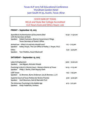
4 Operating Instructions RT-ZC0321354647891 Jaws2 Conventional currentdirection3 Tactile Barrier4 Battery cover856789Battery cover screwJaw triggerON/OFF switchAuto zero buttonLEDSubject to change without notice
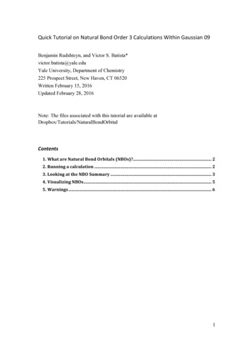
Operating Instructions RT-ZC0221345647891 Jaws2 Conventional currentdirection3 Tactile Barrier4 Battery cover5 Battery cover screw6 Jaw trigger7 ON/OFFand range switch8 Auto zero button9 LEDSubject to change without notice9
Typical performance Plots RT-ZC0310Subject to change without notice
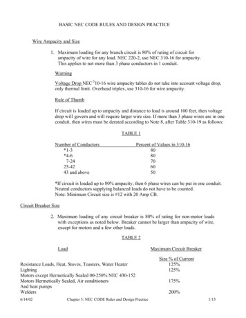
(CP1000)2 m long coaxterminated with asafety BNC connector50 Ohms (CP 1005)Typical performance Plots RT-ZC02CP1005 Frequency ResponseGain dB 1000AGain dB 100A0.5010100100010000100000RelativeinHz)dbGain in dB Gain(wrt 100-0.5-1-1.5-2-2.5-3Frequency (Hz)CP1005 Phase Responsephase 100Aphase 1000A0.0010100100010000100000-5.00Phase Shift in 45.00Frequency (Hz)WarningTo avoid injury, when using the probe ensure that your fingers are behind the protective barrier. Do not use the probeif any part of the probe, including the lead and connector(s),appear to be damaged or if a malfunction of the instrument issuspected.5Subject to change without notice11
4.1 Switch OnWhen the probe is switched on, the green LED will illuminate. The LED starts flashing when the battery voltage is toolow for normal operation and warns the user that it requireschanging. This procedure is described in Section 4.5.4.2 Zero AdjustmentThe output zero offset voltage of the probe may changedue to thermal shifts and other environmental conditions.To null the output voltage depress the Auto Zero button.Ensure that the probe is away from the current carryingconductor whilst the probe is being nulled.4.3 Current Measurement– Switch on the probe and check that the LED is lit.– Connect the output lead to an oscilloscope, multimeteror other measuring equipment.– Zero the probe using the Auto Zero button.– Clamp the jaws of the probe round the conductor ensuring a good contact between the closing faces of thejaws.– Observe and take measurements as required. Positiveoutput indicates that the current flow is in the directionshown by the arrow on the probe.4.4 Auto Power OFFIn order to save battery life, the probe will automaticallyswitch itself off after approximately 10 minutes. To disable the Auto power off function, Switch Off the probe andSwitch On whilst pressing the auto zero button. The redLED will illuminate and the probe will stay On until switchedoff again.4.5 Battery ReplacementWarningTo avoid personal injury, always ensure the probe is removedfrom any live electric circuit, and leads are disconnectedbefore removing the battery cover. Never operate the probewithout the battery cover fitted.The green or red LED will flash when the minimum operating voltage is approached. Use the following procedure.– Unclamp the probe from the conductor, turn it off usingthe On - Off switch and disconnect the output leads,from external equipment.12Subject to change without notice
– Loosen the captive screw which secures the battery cover. Lift the cover through 30 and pull it clear of the probe body. Replace the battery and re-fit the battery coverand fasten the screw .Note:Replacement with other than the specified type of battery willinvalidate the warranty.Fit only the type 9 V PP3 Alkaline (MN 1604).4.6 MaintenanceClean the case periodically by wiping it with a damp clothand detergent. Use isopropyl alcohol to clean the electronics unit and the probe. Do not use abrasive cleaners orsolvents. Do not immerse the probe in liquids.5 Warranty and RepairOur instruments are subject to strict quality controls. Priorto leaving the manufacturing site, each instrument undergoes a 10-hour burn-in test. This is followed by extensivefunctional quality testing to examine all operating modesand to guarantee compliance with the specified technicaldata. The testing is performed with testing equipment thatis calibrated to national standards. The statutory warrantyprovisions shall be governed by the laws of the country inwhich the product was purchased. In case of any complaints, please contact your supplier.The product may only be opened by authorized and qualifiedpersonnel. Prior to working on the product or before the product is opened, it must be disconnected from the AC supplynetwork. Otherwise, personnel will be exposed to the risk ofan electric shock.Any adjustments, replacements of parts, maintenance andrepair may be carried out only by authorized technical personnel. Only original parts may be used for replacing partsrelevant to safety (e.g. power switches, power transformers, fuses). A safety test must always be performed afterparts relevant to safety have been replaced (visual inspection, PE conductor test, insulation resistance measurement,leakage current measurement, functional test). This helpsensure the continued safety of the product.Subject to change without notice13
2020 Rohde & Schwarz GmbH & Co. KGMühldorfstr. 15, 81671 München, GermanyPhone: 49 89 41 29 - 0E-mail: info@rohde-schwarz.comInternet: www.rohde-schwarz.comCustomer Support: www.customersupport.rohde-schwarz.comService: www.service.rohde-schwarz.comSubject to change – Data without tolerance limits is not binding.R&S is a registered trademark of Rohde & Schwarz GmbH & Co. KG.Trade names are trademarks of the owners.Throughout this manual, products from Rohde & Schwarz are indicatedwithout the R&S symbol, e.g. R&S RT-ZC03 is indicated as RT-ZC03.1333.0844.02 Version 03 RT-ZC031333.0850.02 Version 03 RT-ZC02
switch mode power supplies, industrial controllers and other applications requiring current measurement and/or waveform analysis. 2 Safety . The following symbols appear on the products: 14. Subject to change without notice. 1 Introduction. The HZO50 current probe has been designed for use with multimeters and oscilloscopes respectively for .