Transcription
R&S CMA180RADIO TEST SETSpecificationsData SheetVersion 09.00
Version 09.00, March 2021CONTENTSDefinitions . 4At a glance . 5General technical specifications . 6RF generator . 6RF analyzer . 12Spectrum measurements . 17I/Q recorder (R&S CMA-K220 option) . 19AF generator (AF1 OUT, AF2 OUT). 19AF analyzer (AF1 IN, AF2 IN) . 20AF oscilloscope (R&S CMA-K120 option) . 21Digital interface, unbalanced. 21VoIP support (R&S CMA-K610 option) . 21Search routines . 22Digital standards . 23For all digital standard generators and analyzers . 23DMR generator (prerequisite: R&S CMA-B110B/D option) . 23DMR analyzer (R&S CMA-K300, R&S CMA-K305 option) . 23NXDN generator (prerequisite: R&S CMA-B110B/D option) . 23NXDN analyzer . 23DPMR generator (prerequisite: R&S CMA-B110B/D option). 23DPMR analyzer (prerequisite: R&S CMA-K300 option, R&S CMA-K305 option) . 23APCO/P25 generator (prerequisite: R&S CMA-B110B/D option) . 24APCO/P25 analyzer . 24POCSAG generator (R&S CMA-KG260 option, prerequisite: R&S CMA-B110B/D option) . 24TETRA analyzer (R&S CMA-K300 option, prerequisite: R&S CMA-K305 option). 24Zigbee generator (R&S CMA-KG250 option, prerequisite: R&S CMA-B110B/D option) . 24LTE analyzer (R&S CMA-K320 option, R&S CMA-K305 option) . 24User defined generator (R&S CMA-K210 option) . 25Timebase . 25General data . 27Accessories . 30R&S CMA-Z020A transport case. 30R&S CMA-Z025A soft case . 30R&S CMA-Z053A external power supply (prerequisite: R&S CMA-S054M option). 30R&S CMA-B060A battery compartment (prerequisite: R&S CMA-S054M option) . 30R&S CMA-Z061A Li-ion battery (prerequisite: R&S CMA-S054M option, R&S CMA-B060A option) . 31R&S CMA-Z062A Li-ion battery charger for R&S CMA-Z061A Li-ion battery . 31R&S CMA-Z600A AF impedance matching unit (prerequisite: R&S CMA180) . 31R&S CMA-Z680A antenna set . 332Rohde & Schwarz R&S CMA180 Radio Test Set
Version 09.00, March 2021R&S CMA-Z651A 600 Ω set. 33R&S CMA-Z421A radio adapter box and cables. 33R&S CMA-XRT100 setup: R&S CMW100 – model K06. 33Ordering information . 35Recommended extras. 36Recommended extras for manual operation . 36Service options . 37Rohde & Schwarz R&S CMA180 Radio Test Set3
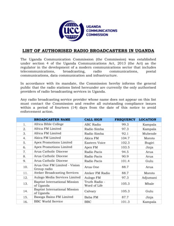
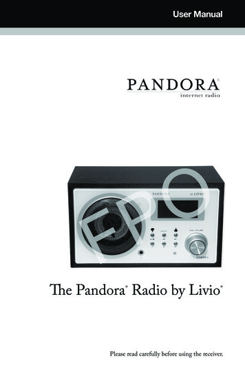
Version 09.00, March 2021DefinitionsGeneralProduct data applies under the following conditions: Three hours storage at ambient temperature followed by 30 minutes warm-up operationSpecified environmental conditions metRecommended calibration interval adhered toAll internal automatic adjustments performed, if applicableSpecifications with limitsRepresent warranted product performance by means of a range of values for the specified parameter. These specifications aremarked with limiting symbols such as , , , , , or descriptions such as maximum, limit of, minimum. Compliance is ensured bytesting or is derived from the design. Test limits are narrowed by guard bands to take into account measurement uncertainties, driftand aging, if applicable.Y-axisSpecification limitActual values with measurement uncertainty and guard bandSpecification limitMeasurement uncertaintiesGuard bandX-axisNon-traceable specifications with limits (n. trc.)Represent product performance that is specified and tested as described under “Specifications with limits” above. However, productperformance in this case cannot be warranted due to the lack of measuring equipment traceable to national metrology standards. Inthis case, measurements are referenced to standards used in the Rohde & Schwarz laboratories.Specifications without limitsRepresent warranted product performance for the specified parameter. These specifications are not specially marked and representvalues with no or negligible deviations from the given value (e.g. dimensions or resolution of a setting parameter). Compliance isensured by design.Typical data (typ.)Characterizes product performance by means of representative information for the given parameter. When marked with , or as arange, it represents the performance met by approximately 80 % of the instruments at production time. Otherwise, it represents themean value.Nominal values (nom.)Characterize product performance by means of a representative value for the given parameter (e.g. nominal impedance). In contrast totypical data, a statistical evaluation does not take place and the parameter is not tested during production.Measured values (meas.)Characterize expected product performance by means of measurement results gained from individual samples.UncertaintiesRepresent limits of measurement uncertainty for a given measurand. Uncertainty is defined with a coverage factor of 2 and has beencalculated in line with the rules of the Guide to the Expression of Uncertainty in Measurement (GUM), taking into accountenvironmental conditions, aging, wear and tear.Device settings and GUI parameters are designated with the format “parameter: value”.Non-traceable specifications with limits, typical data as well as nominal and measured values are not warranted by Rohde & Schwarz.In line with the 3GPP/3GPP2 standard, chip rates are specified in million chips per second (Mcps), whereas bit rates and symbol ratesare specified in billion bits per second (Gbps), million bits per second (Mbps), thousand bits per second (kbps), million symbols persecond (Msps) or thousand symbols per second (ksps), and sample rates are specified in million samples per second (Msample/s).Gbps, Mcps, Mbps, Msps, kbps, ksps and Msample/s are not SI units.4Rohde & Schwarz R&S CMA180 Radio Test Set
Version 09.00, March 2021At a glanceWith its frequency range from 100 kHz to 3 GHz, the R&S CMA180 is ideal for testing all common analog and digital radio systems.Input levels up to 150 W are no problem for the R&S CMA180. The flexible internal switching capabilities for the audio and RF pathsmake the R&S CMA180 suitable for a wide range of test requirements. Users can configure the internal generators, external audiosources, filters and measurements according to the given application. In the predefined test scenarios for receiver, transmitter andduplex tests, the RF and audio paths are preconfigured. This saves time and eliminates configuration errors for standard test cases.The R&S CMA180 features a built-in sweeping spectrum analyzer. Extensive configuration options make this analyzer a universal toolfor testing all types of DUTs. The spectrum analyzer has two operating modes: full span and user-defined spans. The zero span modeenables analysis in the time domain. In combination with the triggers, it is possible, for instance, to display transients. The built-intracking generator makes it easy to determine the frequency response of RF components.The R&S CMA180 can generate test signals for digital radio standards. Signal content can be configured to match test requirements.Signals can carry audio test tones or pseudo random bit sequences (PRBS), for example. Signaling parameters such as DMR colorcode can be configured on the instrument’s intuitive GUI. The integrated vector signal analyzer demodulates digital signals anddelivers results, including eye diagrams and symbol distribution. R&S CMArun is available for test sequence control. It provides agraphical user interface for programming a test sequence. Individual settings and measurement tasks can be configured and arrangedin a specific sequence. Sequences, loops and conditional queries help users easily create and execute complex test sequences. Eachsetting and measurement value is logged and then summarized and stored in a report. For measurements with limit values, pass or failindicators can be displayed.Its outstanding signal quality makes the R&S CMA180 an extremely versatile radio tester for aircraft. The R&S CMA180 can analyzeILS, VOR and marker beacon signals for aircraft landing systems as well as airborne radio signals. Equipped with a battery andantenna, the R&S CMA180 is a standalone instrument that is ideal for aircraft maintenance. The R&S CMA180 incorporates a VoIPgenerator and analyzer in line with EUROCAE ED-137B/C. The VoIP interface is fully integrated in the R&S CMA180.The R&S CMA180 can be equipped with an AC power supply for operation at 110 V to 250 V or a DC power supply for operation at10 V to 30 V. Equipped with a DC power supply, the R&S CMA180 can also be powered via a vehicle’s power supply. The DC powersupply can be connected to an external AC/DC converter for AC operation at 110 V to 250 V. An optional battery pack ensuresmaximum mobility and turns the R&S CMA180 with DC power supply into a portable tester that can be brought directly to the DUT.Rohde & Schwarz R&S CMA180 Radio Test Set5
Version 09.00, March 2021General technical specificationsRF generatorFrequency rangeFrequency resolutionFrequency uncertaintyOutput level rangeRF COM with high-power attenuatorRF COM without high-power attenuatorRF OUTOutput level uncertaintyRF COMRF OUT60.1 MHz to 3000 MHz1 Hzsame as timebase frequency resolution0.1 MHz to 30 MHzcontinuous wave (CW)peak envelope power (PEP)overranging (PEP)30 MHz to 2000 MHzcontinuous wave (CW)peak envelope power (PEP)overranging (PEP)2000 MHz to 3000 MHzcontinuous wave (CW)peak envelope power (PEP)overranging (PEP)0.1 MHz to 30 MHzcontinuous wave (CW)peak envelope power (PEP)overranging (PEP)30 MHz to 2000 MHzcontinuous wave (CW)peak envelope power (PEP)overranging (PEP)2000 MHz to 3000 MHzcontinuous wave (CW)peak envelope power (PEP)overranging (PEP)0.1 MHz to 30 MHzcontinuous wave (CW)peak envelope power (PEP)overranging (PEP)30 MHz to 2000 MHzcontinuous wave (CW)peak envelope power (PEP)overranging (PEP)2000 MHz to 3000 MHzcontinuous wave (CW)peak envelope power (PEP)overranging (PEP)in temperature range from 20 C to 35 C, no overrangingoutput level –120 dBm0.1 MHz to 1 MHz1 MHz to 2000 MHz2000 MHz to 2700 MHz2700 MHz to 3000 MHzoutput level –112 dBm0.1 MHz to 1 MHz1 MHz to 2000 MHz2000 MHz to 2700 MHz2700 MHz to 3000 MHzRohde & Schwarz R&S CMA180 Radio Test Set–141 dBm to –17 dBmup to –17 dBmup to –13 dBm–141 dBm to –15 dBmup to –15 dBmup to –9 dBm–120 dBm to –20 dBmup to –20 dBmup to –13 dBm–128 dBm to 0 dBmup to 0 dBmup to 4 dBm–128 dBm to 2 dBmup to 2 dBmup to 8 dBm–120 dBm to –3 dBmup to –3 dBmup to 4 dBm–120 dBm to 8 dBmup to 8 dBmup to 12 dBm–120 dBm to 10 dBmup to 10 dBmup to 16 dBm–112 dBm to 5 dBmup to 5 dBmup to 12 dBm 1.2 dB 0.7 dB 1.2 dB 1.5 dB 1.2 dB 0.7 dB 1.2 dB 1.5 dB
Version 09.00, March 2021Output level uncertaintyRF COMRF OUTOutput level linearity with fixed RFoutput attenuator setting (digital gain)RF COMOutput level resolutionOutput level repeatabilityOutput level setting rangeRF COM with high-power attenuatorRF COM without high-power attenuatorRF OUTRF power overload protectionRF COM with high-power attenuator("RF COM connector attenuation" in setupmenu)RF COM without high-power attenuator("RF COM connector attenuation" in setupmenu)RF INRF OUTin temperature range from 0 C to 50 C 1, no overrangingoutput level –120 dBm0.1 MHz to 1 MHz1 MHz to 2000 MHz2000 MHz to 2700 MHz2700 MHz to 3000 MHzoutput level –112 dBm0.1 MHz to 1 MHz1 MHz to 2000 MHz2000 MHz to 2700 MHz2700 MHz to 3000 MHzin temperature range from 20 C to 35 C, level range 0 dB to –30 dBno overrangingtypical values after 1 h warm-up time,always returning to same level andfrequency, no temperature change,insignificant time changepossible settings in the HMI,specifications not warranted0.1 MHz to 3000 MHz0.1 MHz to 3000 MHz0.1 MHz to 3000 MHz 2.0 dB 1.0 dB 2.0 dB 2.0 dB 2.0 dB 1.0 dB 2.0 dB 2.0 dB 0.2 dB, 0.1 dB (typ.)0.01 dB 0.02 dB–158 dBm to –9 dBm–141 dBm to 8 dBm–133 dBm to 16 dBmmaximum allowed input power forcontinuous operationmax. allowed input power for 1 min (typ.),at Tamb 25 C, recovery time necessaryshutdown (open)maximum allowed input powershutdown (open)100 Wmaximum allowed input powershutdown (short)maximum allowed reverse input powershutdown (short)100 mW ( 20 dBm)when voltage overload is detected20 mW ( 13 dBm)when voltage overload is detected150 Wwhen thermal overload is detected1 W (typ.)when voltage overload is detectedShutdown: All three connectors are shut down simultaneously; RF COM is switched to open, and RF IN and RF OUT are switched toshort.VSWRRF COM with high-power attenuatorRF COM without high-power attenuatorRF OUT0.1 MHz to 2000 MHz2000 MHz to 2700 MHz2700 MHz to 3000 MHz0.1 MHz to 2000 MHz2000 MHz to 2700 MHz2700 MHz to 3000 MHz0.1 MHz to 2000 MHz2000 MHz to 2700 MHz2700 MHz to 3000 MHz 1.2 1.7 2.0 1.4 1.4 2.0 1.53 1.53 1.53RF OUT is switched to short when off.1With hard disk (R&S CMA-S052B): 5 C to 45 C.Rohde & Schwarz R&S CMA180 Radio Test Set7
Version 09.00, March 2021Attenuation of second harmonicsRF COM with high-power attenuatorRF COM without high-power attenuatorRF OUT0.1 MHz to 3000 MHz, P –27 dBm0.1 MHz to 3000 MHz, P –10 dBm0.1 MHz to 3000 MHz, P –2 dBm 30 dB 30 dB 30 dBAttenuation of third harmonicsRF COM with high-power attenuatorRF COM without high-power attenuatorRF OUT0.1 MHz to 3000 MHz, P –27 dBm0.1 MHz to 3000 MHz, P –10 dBm0.1 MHz to 3000 MHz, P –2 dBm 40 dB 40 dB 40 dBAttenuation of nonharmonicsRF COM, RF OUT,with/without high-power attenuatorNonharmonics, absoluteRF COM with high-power attenuatorPhase noiseResidual FMResidual PMResidual AM8for full-scale CW signal0.1 MHz to 30 MHz 60 dB30 MHz to 2000 MHz, 55 dBexcept fnonharmonic 2659.9375 MHz – fcarrier,except fnonharmonic 2 fcarrier –2659.9375 MHz,except fnonharmonic 2659.9375 MHz2000 MHz to 3000 MHz, 45 dBexcept fnonharmonic 7362.5 MHz – 2 fcarrier,except fnonharmonic 2 fcarrier – 3681.25 MHz,except fnonharmonic 4702.5625 MHz – fcarrierharmonics of 24.576 MHz and 25 MHz,except 175 MHz, 225 MHz, 275 MHz,325 MHz, 375 MHz175 MHz, 225 MHz, 275 MHz, 325 MHz,375 MHzharmonics of 800 MHz920.3125 MHz and 1840.625 MHz2760.9375 MHzsingle sideband, 0.1 MHz to 30 MHz10 kHz offset from carrier100 kHz offset from carrier3 MHz offset from carriersingle sideband, 30 MHz to 890 MHz10 kHz offset from carrier100 kHz offset from carrier3 MHz offset from carriersingle sideband, 890 MHz to 3000 MHz10 kHz offset from carrier100 kHz offset from carrier3 MHz offset from carrier –130 dBm –120 dBm –130 dBm –130 dBm –115 dBm –130 dBc (1 Hz) –130 dBc (1 Hz) –133 dBc (1 Hz) –113 dBc (1 Hz) –115 dBc (1 Hz) –130 dBc (1 Hz) –110 dBc (1 Hz) –110 dBc (1 Hz) –122 dBc (1 Hz)CCITT, RMS0.1 MHz to 30 MHz30 MHz to 2000 MHz2000 MHz to 3000 MHz 2 Hz 3 Hz 5 HzCCITT, RMS0.1 MHz to 30 MHz30 MHz to 2000 MHz2000 MHz to 3000 MHz 0.5 mrad 5 mrad 5 mradCCITT, RMS0.1 MHz to 30 MHz30 MHz to 2000 MHz2000 MHz to 3000 MHz 0.05 % 0.1 % 0.1 %Rohde & Schwarz R&S CMA180 Radio Test Set
Version 09.00, March 2021ModulationModulationCW (off), AM, FM, FM stereo, PM,SSB USB, SSB LSB, ARBAmplitude modulationSourceAM depthModulation frequencyModulation distortionrangeresolutionuncertainty, internal sourceuncertainty, external sourcerangeresolutionCCITT-weightedinternal modulation source,external AF1 IN, AF2 IN,external SPDIF IN0 % to 100 %0.1 % 1% 3%0 Hz to 21 kHz0.1 Hz 1%rangeresolutionuncertainty, internal sourceuncertainty, external sourcerange, internal modulation generatorCCITT-weightedinternal modulation source,external AF1 IN, AF2 IN,external SPDIF IN0 Hz to 100 kHz1 Hz 1% 3%0 Hz to 21 kHz 1%rangeresolutionuncertainty, internal sourceuncertainty, external sourcerange, internal modulation generatorCCITT-weightedinternal modulation source,external AF1 IN, AF2 IN,external SPDIF IN0 rad to 10 rad0.1 mrad 1% 3%0 Hz to 21 kHz 1%Frequency modulationSourceDeviationModulation frequencyModulation distortionPhase modulationSourceDeviationModulation frequencyModulation distortionSSB modulationSourceModulation frequencyCarrier suppressionSideband suppressionupper sideband (USB),lower sideband (LSB)internal modulation source,external AF1 IN, AF2 IN,external SPDIF IN30 Hz to 21 kHz 70 dB 70 dBFM stereo modulationSourceMaximum audio deviationPilot deviationRDS deviationinternal modulation source,external AF1 IN, AF2 IN,external SPDIF IN0 Hz to 90.5 kHz0 Hz to 10 kHz0 Hz to 10 kHzRohde & Schwarz R&S CMA180 Radio Test Set9
Version 09.00, March 2021Internal modulation sourceModulation generatorsFrequency rangebasic tonesquare wave, bandwidth limited to 21 kHzsubtoneresolution, single tone/dual toneresolution, othersCTCSS toneMultitonefrequency rangeNoiseDCSdata raterate offsetFSK deviationmodeslength2 generators,each single tone/multi tone/noise/squarewith additional subtone/CTCSS tone/DCS tone1 Hz to 21 kHz1 Hz to 4 kHz1 Hz to 2 kHz0.1 Hz1 Hztone 1 (67 Hz) to tone 50 (254.1 Hz)1 to 20 selectable tones with individualfrequencies and levels1 Hz to 21 kHzFFT noise, signal composite with flatfrequency response from 0 Hz to 21 kHz134.4 bit/s 30 bit/s0 Hz to 10 kHzoff code, inverted FSK100 ms to 300 msModulation source: DTMF, Selcall, free dialingDTMFDTMF frequenciesSelcallsequencerepetitionpausedigit timedigit pausestandardSelcall frequenciesFree dialingSELCALsequencerepetitionpausedigit timedigit pausesingle tones, dual tonesfrequency range 1st tonefrequency range 2nd toneresolutionsequencerepetitionpausedigit timedigit pausedual tonesfrequency rangeresolutionrepetitionpausedigit timedigit pause10Rohde & Schwarz R&S CMA180 Radio Test Set697 Hz, 770 Hz, 852 Hz, 941 Hz, 1209 Hz,1336 Hz, 1447 Hz, 1633 Hz1 digit to 7 digits1 to 1000 ms to 10000 ms0 ms to 3000 ms0 ms to 3000 msCCIR, EAA, EIA, ZVEI I/II/III, DZVEI,PZVEI1981 Hz, 1124 Hz, 1197 Hz, 1275 Hz,1358 Hz, 1446 Hz, 1540 Hz, 1640 Hz,1747 Hz, 1860 Hz, 2400 Hz, 930 Hz,2247 Hz, 991 Hz, 2110 Hz, 1055 Hz1 digit to 5 digits1 to 1000 ms to 10000 ms0 ms to 3000 ms0 ms to 3000 ms60 Hz to 4000 Hz1200 Hz to 4000 Hz0.1 Hz1 digit to 7 digits1 to 1000 ms to 10000 ms0 ms to 3000 ms0 ms to 3000 ms297.5 Hz to 1553.1 Hz,predefined (A to S) or user defined0.1 Hz1 to 1000 ms to 10000 ms0 ms to 3000 ms0 ms to 3000 ms
Version 09.00, March 2021Modulation source: arbitrary waveform generator (ARB) (R&S CMA-B110B/D option)Memory sizeWord lengthSample lengthSample rateMaximum possible RF bandwidthR&S CMA-B110BR&S CMA-B110DIQmarkerR&S CMA-B110B, with 8-bit markerR&S CMA-B110D, with 8-bit markerminimummaximumdepending on arbitrary waveform fileTriggerTrigger sourcesDelayRepetition1.024 Gbyte4.096 Gbyte16 bit16 bit4 bit to 16 bitup to 214.7 Msampleup to 858.9 Msample400 Hz100 MHz20 MHzexternal TRIG IN0 s to 100 ssingle, continuousInterfererInterfererDelta frequency rangeDelta level rangeModulation0.1 MHz to 3000 MHz 10 MHz 80 dBCW (off), AM, FM, PMVOR/ILS signal generator (R&S CMA-K130 option)VOR modeOutput level range and uncertaintyFrequency bandsBearing30 Hz tone (VAR)9960 Hz carrier (REF)1020 Hz auxiliary tone (IDENT)UncertaintyILS modeOutput level range and uncertaintyFrequency bands90 Hz tone150 Hz tone90 Hz tone and 150 Hz tone1020 Hz auxiliary tone (IDENT)Uncertainty2switchable TO/FROMmodulation frequency, linked for VAR andREFmodulation depth 2modulation frequencyFM deviationmodulation depth 2modulation frequencymodulation depth 2modulation depth, at 30 %modulation frequencyFM deviationbearinglocalizerglideslopemodulation frequency, linked to 150 Hzmodulation frequency, linked to 90 HzSDM 2DDM, depending on SDMphase offsetmodulation frequencymodulation depth 2modulation depth, at SDM 40 % to 80 %modulation frequencyphase offsetDDMsee general technical specifications108 MHz to 117.95 MHz0 to 360 20 Hz to 40 Hz0 % to 100 %7.5 kHz to 12.5 kHz300 Hz to 600 Hz0 % to 100 %0 Hz to 21 kHz0 % to 100 %0.1 %0.05 Hz0.05 Hz0.02 see general technical specifications108.1 MHz to 111.95 MHz329.15 MHz to 335 MHz72 Hz to 108 Hz120 Hz to 180 Hz0 % to 100 %–1 to 1–60 to 120 0 Hz to 21 kHz0 % to 100 %0.1 %0.05 Hz0.05 0.001 FSTotal modulation depth not to exceed 100 %.Rohde & Schwarz R&S CMA180 Radio Test Set11
Version 09.00, March 2021Marker beaconOutput level range and uncertaintyFrequency bandMarker tone1020 Hz auxiliary tone (IDENT)modulation frequencymodulation depth 2modulation frequencymodulation depth 2see general technical specifications75 MHz400 Hz, 1300 Hz, 3000 Hz (selectable)0 Hz to 10 kHz (variable)0 % to 100 %0 Hz to 21 kHz0 % to 100 %RF analyzerRF power overload protectionRF COM with high-power attenuator("RF COM connector attenuation" in setupmenu)RF COM without high-power attenuator("RF COM connector attenuation" in setupmenu)RF INRF OUTmaximum allowed input power forcontinuous operation, at Tamb 30 Cmax. allowed input power for 1 min (typ.),recovery time necessary, at Tamb 30 Cshutdown (open)maximum allowed input powershutdown (open)100 Wmaximum allowed input powershutdown (short)maximum allowed reverse input powershutdown (short)100 mW ( 20 dBm)when voltage overload is detected20 mW ( 13 dBm)when voltage overload is detected150 Wwhen thermal overload is detected1 W (typ.)when voltage overload is detectedShutdown: All three connectors are shut down simultaneously; RF COM is switched to open, and RF IN and RF OUT are switched toshort.Expected nominal power setting rangeRF COM with high-power attenuatorRF COM without high-power attenuatorRF INVSWRRF COM with high-power attenuatorRF COM without high-power attenuatorRF IN0.1 MHz to 3000 MHz0.1 MHz to 3000 MHz0.1 MHz to 3000 MHz–13 dBm to 53 dBm–30 dBm to 36 dBm–36 dBm to 20 dBm0.1 MHz to 2000 MHz2000 MHz to 2700 MHz2700 MHz to 3000 MHz0.1 MHz to 2000 MHz2000 MHz to 2700 MHz2700 MHz to 3000 MHz0.1 MHz to 2000 MHz2000 MHz to 2700 MHz2700 MHz to 3000 MHz 1.2 1.7 2.0 1.4 1.4 2.0 1.58 1.58 1.58RF IN is switched to short when off.Harmonic responseRF COM12second harmonicfin 1 MHz to 1000 MHz,fselected 2 MHz to 2000 MHz,input power near expected nominalpower settingfin 1000 MHz to 1500 MHz,fselected 2000 MHz to 3000 MHz,input power near expected nominalpower settingthird harmonicfin 1 MHz to 666.7 MHz,fselected 3 MHz to 2000 MHz,input power near expected nominalpower settingfin 666.7 MHz to 1000 MHz,fselected 2000 MHz to 3000 MHz,input power near expected nominalpower settingRohde & Schwarz R&S CMA180 Radio Test Set –30 dB –30 dB –50 dB –50 dB
Version 09.00, March 2021Spurious responseInherent spurious responsePhase noiseDynamic rangeRF COM with high-power attenuatorRF COM without high-power attenuatorRF INfor full-scale, single-tone input signal0.1 MHz to 2000 MHz,except fin 1318.46875 MHz fselected2000 MHz to 3000 MHz,except fin 3681.25 MHz – fselected,except fin 3681.25 MHz – 0.5 fselectedwithout input signal, 1 MHz to 3000 MHzexcept fin 2760.9375 MHzexpected nominal power setting –10 dBmexpected nominal power setting –10 dBm, 200 MHz, 400 MHz,425 MHz, 475 MHz, 500 MHz,600 MHz, 2250 MHzexpected nominal power setting –10 dBmsingle sideband, 0.1 MHz to 30 MHz10 kHz offset from carrier100 kHz offset from carrier3 MHz offset from carriersingle sideband, 30 MHz to 913 MHz10 kHz offset from carrier100 kHz offset from carrier3 MHz offset from carriersingle sideband, 913 MHz to 3000 MHz10 kHz offset from carrier100 kHz offset from carrier3 MHz offset from carrierRBW 1 kHz,with fixed expected nominal power setting1 MHz to 2000 MHz, 12 dBm to 51.8 dBm2000 MHz to 3000 MHz, 17 dBm to 51.8 dBm1 MHz to 2000 MHz,–5 dBm to 33 dBm2000 MHz to 3000 MHz,0 dBm to 33 dBm1 MHz to 2000 MHz,–11 dBm to 20 dBm2000 MHz to 3000 MHz,–6 dBm to 20 dBm –55 dB –45 dB –100 dBm –90 dBm –90 dB below expected nominal powersetting –127 dBc (1 Hz) –127 dBc (1 Hz) –130 dBc (1 Hz) –111 dBc (1 Hz) –115 dBc (1 Hz) –130 dBc (1 Hz) –110 dBc (1 Hz) –110 dBc (1 Hz) –125 dBc (1 Hz) 100 dB 95 dB 100 dB 95 dB 100 dB 95 dBPower meterTX test, expert testFrequency rangeFrequency resolutionMeasurement modesResolution bandwidthsExpected nominal power setting rangeMeasurement controlmeasurement timeoutrepetitionstatisticmeasurement lengthstep length0.1 MHz to 3000 MHz1 Hzpower current RMS, power current min.,power current max., power average RMS,power minimum, power maximum,standard deviationGaussi
R&S CMA-Z020A transport case . Test limits are narrowed by guard bands to take into account measurement uncertainties, drift and aging, if applicable. Non-traceable specifications with limits (n. trc.) Represent product performance that is specified and tested as described under "Specifications with limits" above. However, product