Transcription
System Reference ManualJason Kridner edited this page on Jan 15 · 118 revisionsPocketBeagleSystem Reference Manual (SRM)Revision A.x (on-line wiki edition)December 6, 2017Maintaining author: Jason Kridner jkridner@beagleboard.orgContributing Editor: Cathy Wicks cathy@beagleboard.orgTHIS DOCUMENTTerms These design materials are *NOT SUPPORTED* and *DO NOT* constitute a reference design. Only“community” support is allowed via resources at BeagleBoard.org/discuss.THERE IS NO WARRANTY FOR THE DESIGN MATERIALS, TO THE EXTENT PERMITTED BY APPLICABLE LAW.EXCEPT WHEN OTHERWISE STATED IN WRITING THE COPYRIGHT HOLDERS AND/OR OTHER PARTIESPROVIDE THE DESIGN MATERIALS “AS IS” WITHOUT WARRANTY OF ANY KIND, EITHER EXPRESSED ORIMPLIED, INCLUDING, BUT NOT LIMITED TO, THE IMPLIED WARRANTIES OF MERCHANTABILITY ANDFITNESS FOR A PARTICULAR PURPOSE. THE ENTIRE RISK AS TO THE QUALITY AND PERFORMANCE OF THEDESIGN MATERIALS IS WITH YOU. SHOULD THE DESIGN MATERIALS PROVE DEFECTIVE, YOU ASSUME THECOST OF ALL NECESSARY SERVICING, REPAIR OR CORRECTION.In other words, you may use the design materials as you choose and there is no license with regards tousage in the manufacturing process. We mean it, these design materials may be totally unsuitable for anypurposes. Don't blame us!
As a general rule, we don't encourage use of this or other off-the-shelf single board computers incommercial products without engaging with a manufacturer to create a supplier agreement and make surethat you can get material as your business demands. Further, we do update the design on occasions wherewe find it necessary and won't guarantee a supply of older revisions, though we do seek periodicmanufacturing of all of our boards for a period of roughly 10 years and will make design changes to replaceobsolete parts and that may impact your usage. If you do opt to use it in a product, you take fullresponsibility for that product.Do not use the BeagleBoard.org logo or trademarks (such as BeagleBoard, BeagleBone and PocketBeagle) onyour products without a logo license from the BeagleBoard.org Foundation, but feel free to referenceBeagleBoard.org.See the LICENSE file regarding the copyright of these materials.Table of Contents 1.0 Introduction Figure 1. PocketBeagle Home Page2.0 Change History 2.1 Document Change History Table 1. Change History 2.2 Board Changes Table 2. Board History 2.2.1 PocketBone 2.2.2 Rev A1 2.2.3 Rev A23.0 Connecting Up PocketBeagle 3.1 What’s In the Package Figure 2. PocketBeagle Package Figure 3. PocketBeagle Package Insert 3.2 Connecting the board 3.3 Tethered to a PC using Debian Images Figure 4. Tethered Configuration 3.3.1 Getting Started Figure 5. Getting Started Page Figure 6. Download Latest Software Image Figure 7. Download Etcher SD Card Utility Figure 8. Select the PocketBeagle Image Figure 9. Burn the Image to the SD Card Figure 10. Insert the microSD Card into PocketBeagle Figure 11. Insert the micro USB Connector intoPocketBeagle Figure 12. Insert the USB connector into PC Figure 13. Board Power LED Figure 14. User LEDs 3.3.2 Accessing the Board and Getting Started with Coding Figure 15. Interactive Quick Start Guide Launch
Figure 16. Enable a Network Connection Figure 17. Launch Cloud9 IDE 3.3.3 Powering Down Figure 20. Power Button 3.4 Other ways to Connect up to your PocketBeagle4.0 PocketBeagle Overview 4.1 PocketBeagle Features and Specification Table 3. PocketBeagle Features 4.1.1 OSD3358-512M-BSM System in Package 4.2 Board Component Locations Figure 21. Key Board Component Locations5.0 PocketBeagle High Level Specification 5.1 Block Diagram Figure 22. PocketBeagle Key Components 5.2 System in Package (SiP) Figure 23. OSD335x SIP Block Diagram 5.3 Connectivity 5.3.1 Expansion Headers Figure 24. PocketBeagle Expansion Headers 5.3.2 microSD Connector Figure 25. microSD Connector 5.3.3 USB 2.0 Connector Figure 26. USB 2.0 Connector 5.3.4 Boot Modes Table 4. UART Pins on Expansion Headers for Serial Boot 5.4 Power Table 5. Power Inputs Available on Expansion Headers Table 6. Power Outputs Available on Expansion Headers Table 5. Ground Pins Available on Expansion Headers 5.5 JTAG Pads Figure 27. JTAG Pad Connections 5.6 Serial Debug Port Figure 28. Serial Debug Connections6.0 Detailed Hardware Design 6.1 OSD3358-SM SiP Design 6.1.1 SiP A OSD3358 SiP System and Power Signals Figure 29. SiP A OSD3358 SiP System and Power Signals 6.1.2 SiP B OSD3358 SiP JTAG, USB & Analog Signals Figure 30. SiP B OSD3358 SiP JTAG, USB & AnalogSignals 6.1.3 SiP C OSD3358 SiP Peripheral Signals Figure 31. SiP C OSD3358 SiP Peripheral Signals 6.1.4 SiP D OSD3358 SiP System Boot Configuration Figure 32. SiP D OSD3358 SiP System Boot Configuration 6.1.5 SiP E OSD3358 SiP Power Signals Figure 33. SiP E OSD3358 SiP Power Signals 6.1.6 SiP F OSD3358 SiP Power Signals Figure 34. SiP F OSD3358 SiP Power Signals 6.2 MicroSD Connection
6.3 USB Connector Figure 35. microSD ConnectionsFigure 36. USB Connection 6.4 Power Button Design Figure 37. Power Button 6.5 User LEDs Figure 38. User LEDs Table 6. User LED Control Signals/Pins 6.6 JTAG Pads Figure 39. JTAG Pads Design 6.7 PRU-ICSS 6.7.1 PRU-ICSS Features 6.7.2 PRU-ICSS Block Diagram Figure 40. PRU-ICSS Block Diagram 6.7.3 PRU-ICSS Pin Access Table 6. PRU0 and PRU1 Access7.0 Connectors 7.1 Expansion Header Connectors Figure 41. Expansion Headers for PocketBeagle Figure 42. Expansion Header Popular Functions - ColorCoded 7.1.1 P1 Header Figure 43 P1 Header Table 7. P1 Header Pinout 7.1.2 P2 Header Figure 44. P2 Header Table 8. P2 Header Pinout 7.2 mikroBUS socket connections Figure 45. mikroBUS Figure 46. PocketBeagle Both Headers 7.3 Setting up an additional USB Connection8.0 PocketCape Support9.0 PocketBeagle Mechanical 9.1 Dimensions and Weight10.0 Additional Pictures Figure 47. PocketBeagle Front BW Figure 48. PocketBeagle Back BW11.0 Support Information 11.1 Hardware Design 11.2 Software Updates 11.5 Export Information 11.4 RMA Support 11.5 Getting Help
1.0 IntroductionThis document is the System Reference Manual for PocketBeagle and covers its use and design.PocketBeagle is an ultra-tiny-yet-complete Linux-enabled, community-supported, open-source USB-key-fobcomputer. PocketBeagle features an incredible low cost, slick design and simple usage, making it the idealdevelopment board for beginners and professionals alike. Simply develop directly in a web browserproviding you with a playground for programming and electronics. Exploring is made easy with severalavailable libraries and tutorials with many more coming.PocketBeagle will boot directly from a microSD card. Load a Linux distribution onto your card, plug yourboard into your computer and get started. PocketBeagle runs GNU.Linux, so you can leverage many differenthigh-level programming languages and a large body of drivers that prevent you from needing to write a lotof your own software.This design will keep improving as the product matures based on feedback and experience. Softwareupdates will be frequent and will be independent of the hardware revisions and as such not result in achange in the revision number of the board. A great place to find out the latest news and projects forPocketBeagle is on the home page beagleboard.org/pocketFigure 1. PocketBeagle Home PageMake sure you check the support Wiki frequently for the most up to e/wiki
2.0 Change HistoryThis section describes the change history of this document and board. Document changes are not always aresult of a board change. A board change will always result in a document change.2.1 Document Change HistoryTable 1. Change HistoryRevA.xChangesProduction DocumentDateByDecember 7, 2017JK2.2 Board ChangesTable 2. Board HistoryRevChangesDateByA1PreliminaryFebruary 14, 2017JKA2Production. Fixed mikroBUS Click reset pins (made GPIO).September 22, 2017JK2.2.1 PocketBoneUpon the creation of the first, 27mm-by-27mm, Octavo Systems OSD3358 SIP, Jason did a hack two-layerboard in EAGLE called “PocketBone” to drop the Beagle name as this was a totally unofficial effort not gearedat being a BeagleBoard.org Foundation project. The board never worked because the 32kHz and 24MHzcrystals were backwards and Michael Welling decided to pick it up and redo the design in KiCad as a fourlayer board. Jason paid for some prototypes and this resulted in the first successful “PocketBone”, a fullyopen-source 1-GHz Linux computer in a fitting into a mini-mint tin.2.2.2 Rev A1The Rev A1 of PocketBeagle was a prototype not released to production. A few lines were wrong to be ableto control mikroBUS Click add-on board reset lines and they were adjusted.2.2.3 Rev A2The Rev A2 of PocketBeagle was released to production and at World MakerFaire 2017.Known issues in rev A2:
IssueGPIO44 is incorrectly labelled as es/43.0 Connecting Up PocketBeagleThis section provides instructions on how to hook up your board. The most common scenario is tetheringPocketBeagle to your PC for local development.3.1 What’s In the PackageIn the package you will find two items as shown in Figures 2 and 3. PocketBeagle Getting Started instruction card with link to the support URL.Figure 2. PocketBeagle PackageFigure 3. PocketBeagle Package Insert
3.2 Connecting the boardThis section will describe how to connect to the board. Information can also be found on the Quick StartGuide that came in the box. Detailed information is also available at beagleboard.org/getting-startedThe board can be configured in several different ways, but we will discuss the most common scenario. Futurerevisions of this document may include additional configurations.3.3 Tethered to a PC using Debian ImagesIn this configuration, you will need the following additional items: microUSB to USB Type A Cable microSD card ( 4GB and 128GB)The board is powered by the PC via the USB cable, no other cables are required. The board is accessed eitheras a USB storage drive or via a web browser on the PC. You need to use either Firefox or Chrome on the PC,IE will not work properly. Figure 4 shows this configuration.Figure 4. Tethered Configuration
In some instances, such as when additional add-on boards, or PocketCapes are connected, the PC may notbe able to supply sufficient power for the full system. In that case, review the power requirements for theadd-on board/cape; additional power may need to be supplied via the 5v input, but rarely is this the case.3.3.1 Getting StartedThe following steps will guide you to quickly download a PocketBeagle software image onto your microSDcard and get started writing code.1. Navigate to the Getting Started Page beagleboard.org/getting-started Follow along with the instructionsand click on the link noted in Figure 5 below beagleboard.org/latest-images. You can also get to this pagedirectly by going to bbb.io/latestFigure 5. Getting Started Page
2. Download the latest image onto your computer by following the link to the latest image and click on theDebian image for Stretch IoT (non-GUI) for BeagleBone and PocketBeagle via microSD card. See Figure 6below. This will download a .img.xz file into the downloads folder of your computer.Figure 6. Download Latest Software Image
3. Transfer the image to a microSD card.Download and install an SD card programming utility if you do not already have one. Welike https://etcher.io/ for new users and so we show that one in the steps below. Go to your downloads folderand doubleclick on the .exe file and follow the on-screen prompts. See figure 7.Figure 7. Download Etcher SD Card Utility
Insert a new microSD card into a card reader/writer and attach it via the USB connection to your computer.Follow the instructions on the screen for selecting the .img file and burning the image from your computerto the microSD card. Eject the SD card reader when prompted and remove the card. See Figures 8 and 9.Figure 8. Select the PocketBeagle ImageFigure 9. Burn the Image to the SD Card
4. Insert the microSD card into the board - you'll hear a satisfying click when it seats properly into the slot. Itis important that your microSD card is fully inserted prior to powering the system.Figure 10. Insert the microSD Card into PocketBeagle5. Connect the micro USB connector on your cable to the board as shown in Figure 11. The microUSBconnector is fairly robust, but we suggest that you not use the cable as a leash for your PocketBeagle. Takeproper care not to put too much stress on the connector or cable.Figure 11. Insert the micro USB Connector into PocketBeagle
6. Connect the large connector of the USB cable to your Linux, Mac or Windows PC USB port as shown inFigure 12. The board will power on and the power LED will be on as shown in Figure 13 below.Figure 12. Insert the USB connector into PCFigure 13. Board Power LED
7. As soon as you apply power, the board will begin the booting process and the userLEDs Figure 14willcome on in sequence as shown below. It will take a few seconds for the status LEDs to come on, like teachingPocketBeagle to 'stay'. The LEDs will be flashing as it begins to boot the Linux kernel. While the four userLEDS can be over written and used as desired, they do have specific meanings in the image that you'veinitially placed on your microSD card once the Linux kernel has booted. USER0 is the heartbeat indicator from the Linux kernel. USER1 turns on when the microSD card is being accessed USER2 is an activity indicator. It turns on when the kernel is not in the idle loop. USER3 idleFigure 14. User LEDs3.3.2 Accessing the Board and Getting Started with CodingThe board will appear as a USB Storage drive on your PC after the kernel has booted, which will takeapproximately 10 seconds. The kernel on the board needs to boot before the port gets enumerated. Oncethe board appears as a storage drive, do the following:1. Open the USB Drive folder to view the files on your PocketBeagle.2. Launch Interactive Quick Start Guide.Right Click on the file named START.HTM and open it in Chrome or Firefox. This will use your browser toopen a file running on PocketBeagle via the microSD card. You willsee file:///Volumes/BEAGLEBONE/START.htm in the url bar of the browser. See Figure 15 below. Thisaction displays an interactive Quick Start Guide from PocketBeagle.Figure 15. Interactive Quick Start Guide Launch
3. Enable a Network Connection.Click on 'Step 2' of the Interactive Quick Start Guide page to follow instructions to "Enable a NetworkConnection" (pointing to the DHCP server that is running on PocketBeagle). Copy the appropriate IP Addressfrom the chart (according to your PC operating system type) and paste into your browser then adda :3000 to the end of it. See example in Figure 16 below. This will launch from PocketBeagle one of it'sfavorite Web Based Development Environments, Cloud9 IDE, (Figure 17) so that you can teach your beaglenew tricks!Figure 16. Enable a Network Connection
Figure 17. Launch Cloud9 IDE4. Get Started Coding with Cloud9 IDE - blinking USR3 LED in JavaScript using the BoneScript library example1. Create a new text file
2. Copy and paste the below code into the editor3. var b require('bonescript');4. var state b.LOW;5. b.pinMode("USR3", b.OUTPUT);6. setInterval(toggle, 250);// toggle 4 times a second, every 250ms7. function toggle() {8.if(state b.LOW) state b.HIGH;9.else state b.LOW;10.b.digitalWrite("USR3", state);11. }
12. Save the new text file as blinkusr3.js within the default directory13. Executenode blinkusr3.js
within the default (/var/lib/cloud9) directory14. Type CTRL C to stop the program running3.3.3 Powering Down1. Standard Power Down Press the power button momentarily with a tap. The system will power downautomatically. This will shut down your software with grace. Software routines will run to completion.The Standard Power Down can also be invoked from the Linux command shell via "sudo shutdown -h now".2. Hard Power Down Press the power button for 10 seconds. This will force an immediate shut down of thesoftware. For example you may lose any items you have written to the memory. Holding the button longerthan 10 seconds will perform a power reset and the system will power back on.3. Remove the USB cable Remember to hold your board firmly at the USB connection while you remove thecable to prevent damage to the USB connector.4. Powering up again. If you'd like to power up again without removing the USB cable follow theseinstructions:1. If you used Step 1 above to power down, to power back up, hold the power button for 10 seconds,release then tap it once and the system will boot normally.2. If you used Step 2 above to power down, to power back up, simply tap the power button and thesystem will boot normally.Figure 20. Power Button
3.4 Other ways to Connect up to your PocketBeagleThe board can be configured in several different ways. Future revisions of this document may includeadditional configurations.As other examples become documented, we'll update them on the Wiki /wiki See also the on-line discussion.4.0 PocketBeagle OverviewPocketBeagle is built around Octavo Systems' OSD335x-SM System-In-Package that integrates a highperformance Texas Instruments AM3358 processor, 512MB of DDR3, power management, nonvolatile serialmemory and over 100 passive components into a single package. This integration saves board space byeliminating several packages that would otherwise need to be placed on the board, but more notablysimplifies our board design so we can focus on the user experience.The compact PocketBeagle design also offers access through the expansion headers to many of theinterfaces and allows for the use of add-on boards called PocketCapes and Click Boards fromMikroElektronika, to add many different combinations of features. A user may also develop their own boardor add their own circuitry.4.1 PocketBeagle Features and SpecificationThis section covers the specifications and features of the board in a chart and provides a high leveldescription of the major components and interfaces that make up the board.Table 3. PocketBeagle FeaturesFeatureSystem-In-'Octavo Systems OSD335x-SM in 256 Ball BGA (21mm x 21mm)
PackageSiP Incorporates :ProcessorTexas Instruments 1GHz Sitara AM3358 ARM Cortex -A8 with NEONfloating-point acceleratorGraphics EngineImagination Technologies PowerVR SGX530 Graphics AcceleratorReal-Time Units2x programmable real-time unit (PRU) 32-bit 200MHz microcontrollers withsingle-cycle I/O latencyCoprocessorARM Cortex -M3 for power management functionsSDRAM Memory512MB DDR3 800MHz RAMNon-VolatileMemory4KB I2C EEPROM for board configuration informationPowerManagementTPS65217C PMIC along with TL5209 LDO to provide power to the system withintegrated 1-cell LiPo battery supportConnectivity :SD/MMCBootable microSD card slotUSBHigh speed USB 2.0 OTG (host/client) micro-B connectorDebug SupportJTAG test points and gdb/other monitor-mode debug possiblePower SourcemicroUSB connector, also expansion header options (battery, VIN or USB-VIN)User I/OPower Button with press detection interrupt via TPS65217C PMICExpansion Header :USBHigh speed USB 2.0 OTG (host/client) control signalsAnalog Inputs8 analog inputs with 6 @ 1.8V and 2 @ 3.3V along with 1.8V referencesDigital I/O44 digital GPIOs accessible with 18 enabled by default including 2 shared with the3.3V analog input pins
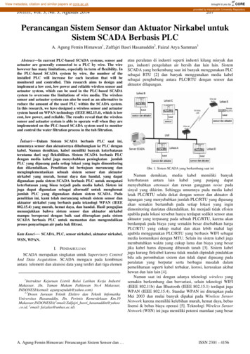
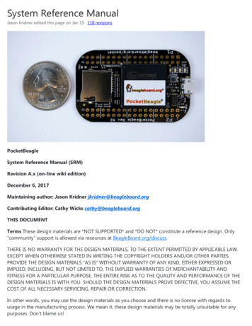
UART3 UARTs accessible with 2 enabled by defaultI2C2 I2C busses enabled by defaultSPI2 SPI busses with single chip selects enabled by defaultPWM4 Pulse Width Modulation outputs accessible with 2 enabled by defaultQEP2 Quadrature encoder inputs accessibleCAN2 CAN bus controllers accessible4.1.1 OSD3358-512M-BSM System in PackageThe Octavo Systems OSD3358-512M-BSM System-In-Package (SiP) is part of a family of products that arebuilding blocks designed to allow easy and cost-effective implementation of systems based in TexasInstruments powerful Sitara AM335x line of processors. The OSD335x-SM integrates the AM335x along withthe TI TPS65217C PMIC, the TI TL5209 LDO, up to 1 GB of DDR3 Memory, a 4 KB EEPROM for non-volatileconfiguration storage and resistors, capacitors and inductors into a single 21mm x 21mm design-in-readypackage.With this level of integration, the OSD335x-SM family of SiPs allows designers to focus on the key aspects oftheir system without spending time on the complicated high-speed design of the processor/DDR3 interfaceor the PMIC power distribution. It reduces size and complexity of design.Full Datasheet and more information is available at octavosystems.com/octavo products/osd335x-sm/4.2 Board Component LocationsThis section describes the key components on the board, their location and function.Figure 21 below shows the locations of the devices, connectors, LEDs, and switches on the PCB layout of theboard.Figure 21. Key Board Component Locations
Key Components The Octavo Systems OSD3358-512M-BSM System-In-Package is the processor system for theboard P1 and P2 Headers come unpopulated so a user may choose their orientation User LEDs provides 4 programmable blue LEDs Power BUTTON can be used to power up or power down the board (see section 3.3.3 for details) USB 2.0 OTG is a microUSB connection to a PC that can also power the board Power LED provides communication regarding the power to the board microSD slot is where a microSD card can be installed.5.0 PocketBeagle High Level SpecificationThis section provides the high level specification of PocketBeagle.5.1 Block DiagramFigure 22 below is the high level block diagram of PocketBeagle.Figure 22. PocketBeagle Key Components
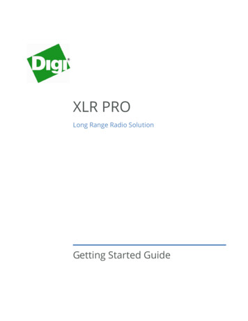
5.2 System in Package (SiP)The OSD335x-SM Block Diagram is detailed in Figure 23 below. More information, including designresources are available on the 'Octavo Systems Website'Figure 23. OSD335x SIP Block Diagram
Note: PocketBeagle utilizes the 512MB DDR3 memory size version of the OSD335x-SM A few of the featuresof the OSD335x-SM SiP may not be available on PocketBeagle headers. Please check Section 7 for the P1 andP2 header pin tables.5.3 Connectivity5.3.1 Expansion HeadersPocketBeagle gives access to a large number of peripheral functions and GPIO via 2 dual rail expansionheaders. With 36 pins each, the headers have been left unpopulated to enable users to choose the headerconnector orientation or add-on board / cape connector style. Pins are clearly marked on the bottom of theboard with additional pin configurations available through software settings. Detailed information is availablein Section 7.Figure 24. PocketBeagle Expansion Headers
5.3.2 microSD ConnectorThe board is equipped with a single microSD connector to act as the primary boot source for the board. Justabout any microSD card you have will work, we commonly find 4G to be suitable.When plugging in the SD card, the writing on the card should be up. Align the card with the connector andpush to insert. Then release. There should be a click and the card will start to eject slightly, but it then shouldlatch into the connector. To eject the card, push the SD card in and then remove your finger. The SD card willbe ejected from the connector. Do not pull the SD card out or you could damage the connector.Figure 25. microSD Connector5.3.3 USB 2.0 ConnectorThe board has a microUSB connector that is USB 2.0 HS compatible that connects the USB0 port to the SiP.Generally this port is used as a client USB port connected to a power source, such as your PC, to power theboard. If you would like to use this port in host mode you will need to supply power for peripherals viaHeader P1 pin 7 (USB1.VIN) or through a powered USB Hub. Additionally, in the USB host configuration, youwill need to power the board through Header P1 pin 1 (VIN) or Header P1 pin 7 (USB1.VIN) or Header P2 pin14 (BAT.VIN)Figure 26. USB 2.0 Connector
5.3.4 Boot ModesThere are three boot modes: SD Boot: MicroSD connector acts as the primary boot source for the board. This is described inSection 3. USB Boot: This mode supports booting over the USB port. More information can be found in theproject called "BeagleBoot" This project ported the BeagleBone bootloader server BBBlfs(currentlywritten in c) to JavaScript(node.js) and make a cross platform GUI (using electron framework) flashingtool utilizing the etcher.io project. This will allow a single code base for a cross platform tool. For moreinformation on BeagleBoot, see the BeagleBoot Project Page. Serial Boot: This mode will use the serial port to allow downloading of the software. A separate USBto TTL level serial UART converter cable is required or you can connect one of theMikroelektronika FTDI Click Boards to use this method. The UART pins on PocketBeagle's expansionheaders support the interface. For more information regarding the pins on the expansion headers andvarious modes, see Section 7.Table 4. UART Pins on Expansion Headers for Serial BootHeader.PinSilkscreenProc BallSiP BallPin Name (Mode 0)P1.22GNDP1.30U0 TXE16B12uart0 txdP1.32U0 RXE15A12uart0 rxdGNDIf the Serial Boot is not in use, the UART0 pins can be used for Serial Debug. See Section 5.6 for moreinformation.Software to support USB and serial boot modes is not provided by beagleboard.org. Please contact TIfor support of this feature.5.4 PowerThe board can be powered from three different sources: A USB port on a PC. A power supply with a USB connector.
Expansion Header pins.Note: VIN-USB is directly shorted between the USB connector on PocketBeagle and USB1 VI on theexpansion headers. You should only source power to the board over one of these and may optionally use theother as a power sink.The tables below show the power related pins available on PocketBeagle's Expansion Headers.Table 5. Power Inputs Available on Expansion HeadersHeader.PinSilkscreenP1.01Proc BallSiP BallPin Name (Mode 0)VINP10, R10, T10VINP1.07USB1 VIP9, R9, T9VIN-USBP2.14BAT P8, R8, T8VIN-BATSiP BallPin Name (Mode 0)Table 6. Power Outputs Available on Expansion HeadersHeader.PinSilkscreenProc BallP1.14 3.3VF6, F7, G6, G7VOUT-3.3VP1.24VOUTK6, K7, L6, L7VOUT-5VP2.13VOUTK6, K7, L6, L7VOUT-5VP2.23 3.3VF6, F7, G6, G7VOUT-3.3VTable 5. Ground Pins Available on Expansion HeadersHeader.PinSilkscreenProc BallSiP BallPin Name (Mode 0)P1.15USB1 GNDGNDP1.16GNDGNDP1.22GNDGNDP2.15GNDGNDP2.21GNDGND
Note: A comprehensive tutorial for Power Inputs and Outputs for the OSD335x System in Package isavailable in the 'Tutorial Series' on the Octavo Systems website.5.5 JTAG PadsPads for an optional connection to a JTAG emulator has been provided on the back of PocketBeagle. Moreinformation about JTAG emulation can be found on the TI website - 'Entry-level debug through fullcapability development'Figure 27. JTAG Pad Connections5.6 Serial Debug PortSerial debug is provided via UART0 on the processor. See Section 5.3.4 for the Header Pin table. Signalssupported are TX and RX. None of the handshake signals (CTS/RTS) are supported. A separate USB to TTLlevel serial UART converter cable is required or you can connect one of the Mikroelektronika FTDI ClickBoardsto use this method.Figure 28. Serial Debug Connections
If serial boot is not used, the UART0 can be used to view boot messages during startup and can provideaccess to a console using a terminal access program like Putty. To view the boot messages or use theconsole the UART should be set to a baud rate of 115200 and use 8 bits for data, no parity bit and 1 stop bit(8N1).6.0 Detailed Hardware DesignThe following sections contain schematic references for PocketBeagle. Full schematics in both PDF and Eagleare available on the 'PocketBeagle Wiki'6.1 OSD3358-SM SiP DesignSchematics for the OSD3358-SM SiP are divided into several diagrams.6.1.1 SiP A OSD3358 SiP System and Power SignalsFigure 29. SiP A OSD3358 SiP System and Power Signals
6.1.2 SiP B OSD3358 SiP JTAG, USB & Analog SignalsFigure 30. SiP B OSD3358 SiP JTAG, USB & Analog Signals
6.1.3 SiP C OSD3358 SiP Peripheral SignalsFigure 31. SiP C OSD3358 SiP Peripheral Signals
6.1.4 SiP D OSD3358 SiP System Boot ConfigurationFigure 32. SiP D OSD3358 SiP System Boot Configuration
6.1.5 SiP E OSD3358 SiP Power SignalsFigure 33. SiP E OSD3358 SiP Power Signals6.1.6 SiP F OSD3358 SiP Power SignalsFigure 34. SiP F OSD3358 SiP Power Signals
6.2 MicroSD ConnectionThe Micro Secure Digital (microSD) connector design is highlighted in Figure 35.Figure 35. microSD Connections6.3 USB ConnectorThe USB connector design is highlighted in Figure 36.Note that there is an ID pin for dual-role (host/client) functionality. The hardware fully supports it, but careshould be taken to ensure the kernel in use is either statically or dynamically configured to recognize andutilize the proper mode.Figure 36. USB Connection
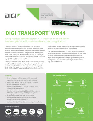
6.4 Power Button DesignThe power button design is highlighted in Figure 37.Figure 37. Power Button6.5 User LEDsThere are four user programmable LEDs on PocketBeagle. The design is highlighted in Figure 38. Table 6Provides the LED control signals and pins. A logic level of "1" will cause the LEDs to turn on.Figure 38. User LEDs
Table 6. User LED Control Signals/PinsLEDSignal NameProc BallSiP BallUSR0GPIO1 21V15P13USR1GPIO1 22U15T14USR2GPIO1 23T15R14USR3GPIO1 24V16P146.6 JTAG PadsThere are 7 pads on the bottom of PocketBeagle to connect JTAG for debugging. The design is highlightedin Figure 39. More information regarding JTAG debugging can be found at 'www.ti.com/jtag'Figure 39. JTAG Pads Design
6.7 PRU-ICSSThe Programmable Real-Time Unit Subsystem and Industrial Communication SubSystem (PRU-ICSS) moduleis located inside the AM3358 processor, which is inside the Octavo Systems SiP. Commonly referred to as justthe "PRU", this little s
SiP A OSD3358 SiP System and Power Signals 6.1.2 SiP B OSD3358 SiP JTAG, USB & Analog Signals Figure 30. SiP B OSD3358 SiP JTAG, USB & Analog Signals 6.1.3 SiP C OSD3358 SiP Peripheral Signals Figure 31. SiP C OSD3358 SiP Peripheral Signals 6.1.4 SiP D OSD3358 SiP System Boot Configuration Figure 32. SiP D OSD3358 SiP System Boot Configuration