Transcription
UNIVERSITY OF VAASASCHOOL OF TECHNOLOGY AND INNOVATIONWIRELESS INDUSTRIAL AUTOMATIONAkpojoto Akporido SiemuriROBUST AND RELIABLE WIRELESS COMMUNICATION BETWEENSMART NOX SENSOR AND THE SPEEDGOAT/ENGINE CONTROLMODULEA case study of Wärtsilä’s smart NOx sensor and W4L20 Diesel EngineMaster s thesis for the degree of Master of Science in Technology submitted for inspection, Vaasa, 13 February, 2019.SupervisorInstructorsProfessor Timo MantereM.Sc. Tobias GlockerAssistant Professor Mike MekkanenVAASA 2019
1ACKNOWLEDGEMENTFirst, I am thankful to God for His wisdom and guidance through my master’s studies. Iwould like to thank Professor Mohammed Elmusrati and Reino Virrankoski for the opportunity to work on the Wärtsilä smart NOx sensor case under the Work Packet 3(WP3 – Wireless Communication) in the Smart Energy Systems Research Platform(SESP) project. I am also thankful to Professor Kimmo Kauhaniemi and Assistant Professor Mike Mekkanen for an excellent guidance through the SESP WP3 project to itscompletion.I will like to mention my gratitude to Professor Timo Mantere and Tobias Glocker foran excellent supervision and guidance in achieving success in the completion of my thesis. I am also thankful to the laboratory engineers in Technobothnia, Veli-Matti Eskonen and Juha Miettinen, for providing all the necessary equipment and a good workingenvironment and to Xiaoguo Storm for helping with the smart NOx/speedgoat tests inVEBIC. Thanks to Rayko Toshev, Sulaymon Tajudeen and Ibukun Odubogun for giving access to the digital manufacturing laboratory in Technobothnia and providing therelevant equipment to achieve the 3D printing aspects applied in this thesis and toSulaymon Tajudeen for assisting in the design of the models that was 3D printed.Lastly, I am thankful to everyone who supported me in any way towards the completionof this thesis.
TABLE OF CONTENTSpageACKNOWLEDGEMENT1LIST OF FIGURES5LIST OF TABLES8ABBREVIATIONS10ABSTRACT131. INTRODUCTION151.1. Motivation151.2. Objectives161.3. Methods161.4. Thesis Structure172. INTRODUCTION OF PROTOCOLS AND MAJOR COMPONENTS2.1. Controller Area Network (CAN)18182.1.1. The CAN Bus192.1.2. CAN Standard202.1.3. CAN Messages222.2. Wireless Communication Protocols242.2.1. Factors that affect wireless communication252.2.2. Types of Wireless Communication Protocols272.2.3. Bluetooth Low Energy (BLE)282.2.4. Zigbee (IEEE 802.15.4)322.2.5. WiFi (IEEE 802.11 b/g/a)372.2.6. LoRa (Long Range)402.2.7. Comparing the Wireless Communication Protocols472.2.8. Choosing a Wireless Protocol492.2.9. Basic Network Attacks50
32.2.10. Encryption and Authentication2.3. Smart NOx Sensor, Speedgoat and Engine Control Module (ECM)52522.3.1. Smart NOx Sensor522.3.2. Acquiring data from the Smart NOx sensor552.3.3. Testing the Smart NOx sensor562.3.4. Calculating O2% and NOx ppm572.3.5. Speedgoat and the Engine Control Module (ECM)573. SMART NOX AND SPEEDGOAT WIRELESS COMMUNICATION583.1. System Architecture593.2. System Overview733.2.1. Connecting the Smart NOx Sensor733.2.2. The BLE-CAN bridge Hardware733.2.3. The BLE-CAN bridge Software763.2.4. The XBee-CAN bridge Hardware783.2.5. The XBee-CAN bridge Software803.2.6. The WIFI-CAN bridge Hardware833.2.7. The WIFI-CAN bridge Software853.2.8. The LoRa-CAN bridge Hardware873.2.9. The LoRa-CAN bridge Software893.2.10. Flowchart for codes and Viewing the CAN frames913.2.11. Connecting to the Speedgoat953.3. Wireless Communication Performance Measure4. EXPERIMENT AND ANALYSIS96974.1. Details of Transmitted Payload and LCD Display for XBee-CAN Modules 984.2. Bluetooth Low Energy (BLE)994.2.1. BLE RSSI Values994.2.2. BLE Packet Loss1004.2.3. BLE Latency1014.3. XBee (IEEE 802.15.4)1014.3.1. XBee RSSI Values1014.3.2. XBee Packet Loss102
4.3.3. XBee Latency1034.4. WIFI (IEEE 802.11 b/g/a)1034.4.1. WIFI RSSI Values1034.4.2. WIFI Packet Loss1044.4.3. WIFI Latency1054.5. LoRa (Long Range)1054.5.1. LoRa RSSI Values1054.5.2. LoRa Packet Loss1064.5.3. LoRa Latency1074.6. Bit Error Check for all wireless protocols1074.7. Security Implementation1084.8. Power Comsumption1084.9. Comparing the Wireless Solutions Based on the Analysis of Results1094.10. Viewing O2% and NOx ppm Values on the Speedgoat1144.11. SmartNOx XBee-CAN Module Test on Wärtsilä W4L20 Diesel Engine 1154.12. Applying Additive Manufacturing (3D printing) to the Designed Prototype 1205. CONCLUSION AND FUTURE WORK121LIST OF REFERENCES124APPENDICES134APPENDIX 1. Schematic of Mikroelectronika CAN SPI click board134APPENDIX 2. Smart NOx, XBee-CAN Module and Speedgoat system overview 135APPENDIX 3. LCD Display for Transmitter/Receiver Modules136APPENDIX 4. Sample output of transmitter and receiver code137APPENDIX 5. 3D printed protective casing body138APPENDIX 6. 3D printed protective casing covers138
5LIST OF FIGURESFigure 1.CAN Bus Architecture19Figure 2. ISO11898 Architecture20Figure 3. CAN 2.0A - Standard CAN Frame 11-Bit Identifier21Figure 4. CAN 2.0B - Extended CAN Frame 29-Bit Identifier22Figure 5. Arbitration on a CAN Bus23Figure 6. Fresnel zone illustration25Figure 7. Bluetooth Low Energy Frequency Channels30Figure 8. Zigbee Packet Structure33Figure 9. ZigBee Protocol Stack Architecture34Figure 10. Application Layer Security36Figure 11. Network Layer Security36Figure 12. Application and Network Layer Security37Figure 13: LoRa Packet Structure42Figure 14. A Simplified SX1272 Block Diagram45Figure 15. LoRa Network Architecture46Figure 16. Types of network attacks51Figure 17. Schematic representation of an amperometric NOx sensor54Figure 18. CAN frame to start heating smart NOx56Figure 19. Engine Control Unit of a 1996 Chevrolet Beretta58Figure 20. CAN Bus Module60Figure 21. Multiprotocol Radio Shield v2.061Figure 22. Arduino UNO Rev.362Figure 23. Arduino IDE63
Figure 24. Waspmote development board63Figure 25. Waspmote IDE64Figure 26. Waspmote Expansion Board64Figure 27. XBee PRO Module66Figure 28. XBee Explorer USB66Figure 29. XBee PRO Module on XBee Explorer USB66Figure 30. XCTU tool67Figure 31. LoRa Module68Figure 32. WIFI PRO Module69Figure 33. Waspmote Bluetooth Low Energy module69Figure 34. Smart NOx sensor from Wärtsilä71Figure 35. Speedgoat – A performance real-time target machine71Figure 36. Simulink model to receive smart NOx CAN frames72Figure 37. Hardware setup of BLE-CAN bridge74Figure 38. Block diagram for the hardware setup of BLE-CAN bridge75Figure 39. Smart NOx sensor and BLE-CAN transmitter77Figure 40. BLE-CAN receiver and Kvaser Leaf Light HS v2 USB77Figure 41. Hardware setup of Xbee-CAN bridge78Figure 42. Block diagram for the hardware setup of XBee-CAN bridge79Figure 43. Smart NOx sensor and XBee-CAN transmitter80Figure 44. XBee-CAN receiver and Kvaser Leaf Light HS v2 USB81Figure 45. Hardware setup of WIFI-CAN bridge83Figure 46. Block diagram for the hardware setup of WIFI-CAN bridge84Figure 47. Smart NOx sensor and WIFI-CAN transmitter85
7Figure 48. WIFI-CAN receiver and Kvaser Leaf Light HS v2 USB86Figure 49. Hardware setup of LoRa-CAN bridge87Figure 50. Block diagram for the hardware setup of LoRa-CAN bridge88Figure 51. Smart NOx sensor and LoRa-CAN transmitter89Figure 52. LoRa-CAN receiver and Kvaser Leaf Light HS v2 USB90Figure 53. Flowchart for the XBee, WiFi and LoRa transmitter codes92Figure 54. Flowchart for the XBee, WiFi and LoRa receiver codes93Figure 55. Hexadecimal View of the CAN frames94Figure 56. Decimal View of the CAN frames94Figure 57. Continuously updated sliding graph for O2% and NOx ppm values95Figure 58. Transmitted Smart NOx Payload98Figure 59. RSSI Measurements for all the wireless protocol in Technobothnia111Figure 60. RSSI Measurements for all the wireless protocol in VEBIC112Figure 61. Continuously updated sliding graph for O2% and NOx ppm values115Figure 62. Speedgoat result when Wärtsilä W4L20 Diesel Engine is idle117Figure 63. Wärtsilä W4L20 Diesel Engine is running without load117Figure 64. Speedgoat sliding graph of the O2% and NOx ppm values118Figure 65. Speedgoat results for O2% and NOx ppm values118Figure 66. Wärtsilä W4L20 Diesel Engine is running with load119Figure 67. Speedgoat sliding graph of the O2% and NOx ppm values119Figure 68. Speedgoat results for O2% and NOx ppm values119Figure 69. XBee-CAN Receiver/Transmitter in 3D printed protective casings121
8LIST OF TABLESTable 1. Main Features of BLE that differ from standard Bluetooth29Table 2. BLE Radio feature31Table 3. LoRa Device Variants and Key Parameters taken from LoRaSX1272/73 Datasheet, Rev. 3.1. Semtech, 201742Table 4. Comparing BLE, XBee, WIFI and LoRa Wireless Protocols48Table 5. Payload in smart NOx CAN frames56Table 6. Technical details of the CAN Bus Module60Table 7. XBee 802.15.4 Channel Number Frequency65Table 8. LoRa specification68Table 9. Main features of the BLE module70Table 10. NOx sensor performance specification70Table 11. Smart NOx sensor pin labeling73Table 12. BLE maximum and minimum RSSI measurement in Technobothnia99Table 13. BLE maximum and minimum RSSI measurement in VEBIC99Table 14. BLE maximum and minimum Packet Loss measurementin Technobothnia100Table 15. BLE maximum and minimum Packet Loss measurement in VEBIC100Table 16. BLE maximum and minimum latency measurement in milliseconds101Table 17. XBee maximum and minimum RSSI measurement in Technobothnia102Table 18. XBee maximum and minimum RSSI measurement in VEBIC102Table 19. XBee maximum and minimum Packet Loss measurementin TechnobothniaTable 20. XBee maximum and minimum Packet Loss measurement in VEBIC102102
9Table 21. XBee maximum and minimum latency measurement in milliseconds103Table 22. WIFI maximum and minimum RSSI measurement in Technobothnia104Table 23. WIFI maximum and minimum RSSI measurement in VEBIC104Table 24. WIFI maximum and minimum Packet Loss measurementin Technobothnia104Table 25. WIFI maximum and minimum Packet Loss measurement in VEBIC105Table 26. WIFI maximum and minimum latency measurement in milliseconds105Table 27. LoRa maximum and minimum RSSI measurement in Technobothnia106Table 28. LoRa maximum and minimum RSSI measurement in VEBIC106Table 29. LoRa maximum and minimum Packet Loss measurementin Technobothnia106Table 30. LoRa maximum and minimum Packet Loss measurement in VEBIC107Table 31. LoRa maximum and minimum latency measurement in milliseconds107Table 32. Computed Battery Life of Transmitter and Receiver Modules109Table 33. Comparison of the wireless protocols based on the analysis of results110Table 34. Comparison of the values from SICK and Smart NOx sensor for theWärtsilä W4L20 Diesel Engine for different operation modes116
10ABBREVIATIONSAESAdvanced Encryption StandardBLEBluetooth Low EnergyBERBit Error RateCADComputer Aided DesignCANController Area NetworkCBCCipher Block ChainingdBmdecibel-milliwattsDDMDirect Digital ManufacturingECMEngine Control ModuleECUEngine Control UnitIDEIntegrated Development EnvironmentIEEEInstitute of Electrical and Electronics EngineersISOInternational Standard OrganizationLCDLiquid Crystal DisplayLoRaLong RangemAhMilliampere hourMCP2515MicrochipmsMillisecondsNOxNitrogen oxideO2OxygenOSIOpen System InterconnectionOTAOver the Airppmparts per millionQoSQuality of ServiceRSSIReceived Signal Strength IndicatorSAESociety of Automotive EngineersSPISerial Peripheral InterfaceTCP/IPTraffic Control Protocol/Internet ProtocolµAMicroampereUARTUniversal Asynchronous Receiver/Transmitter
11USBUniversal Serial BusVEBICVaasa Energy Business Innovation CentreWEPWired Equivalent PrivacyWiFiWireless FidelityWSNWireless Sensor NetworkZCZigBee CoordinatorZDOZigBee Device ObjectZEDZigBee End DeviceZRZigBee Router
12
13UNIVERSITY OF VAASASchool of Technology and InnovationAuthor:Akpojoto SiemuriTopic of the Thesis:Robust and Reliable Wireless Communication Between the Smart NOx Sensor andthe Speedgoat/Engine Control ModuleSupervisor:Professor Timo MantereInstructors:M.Sc. Tobias GlockerAssistant Professor Mike MekkanenDepartment:Department of Computer ScienceDegree:Master of Science in TechnologyDegree Programme:Wireless Industrial AutomationYear of entering the University:2016Year of completing the thesis:2019Number of pages:138ABSTRACTIn recent years, the industrial applications of the wireless transmission of data acquiredthrough sensors have been growing. Addressing the challenges or requirements thatcome with this needs the integration of new product designs and manufacturing techniques with automation devices. Factors like development time, security, reliability,transmission in an industrial environment, data rate, battery life with energy harvestingcapabilities, etc. are of major concerns.This thesis is based on the Wärtsilä smart NOx sensor case study which investigates thepossibility of replacing the existing wired CAN bus connection between the smart NOxsensor and the rapid control prototyping system speedgoat and possibly in the future theEngine Control Unit (ECU) with a wireless communication solution. The designed prototype would wirelessly transmit the smart NOx sensor data. The smart NOx sensor datais received using a CAN bus integrated with a wireless transmitter module. The wirelessreceiver module receives the data and then relays the CAN frames through an integratedCAN Bus to the speedgoat. A matlab simulink module has been programmed into thespeedgoat to receive the CAN frames, calculate O2% and NOx ppm values and displaythe results on a monitor connected to the speedgoat. Criteria like transmission in industrial environments, packet loss, RSSI, bit error rate, reliability and security of the wireless solution are analyzed. According to the analysis done and best practices, a wirelesssolution is recommended and implemented. The wireless-CAN prototype is installed onthe Wärtsilä W4L20 diesel engine in VEBIC for monitoring and observation.KEY WORDS: BLE, CAN Bus, Engine Control Module (ECM), LoRa,RSSI: Received Signal Strength Indicator, Smart NOx sensor,Speedgoat, Wi-Fi, Wireless Communication, ZigBee
14
151. INTRODUCTIONModern industries’s rapid development and increase in the economics of scale leads toproduction and industrial automation. These brings about the need to transfer data andthe integration of data. This can be achieved using wireless communication, therefore,analysis of some well-known wireless communication solutions is crucial in achievingreliable and flexible data transfer. (Gao, Huang, Chen, Jin, & Luo 2013.)Wireless connectivity offers multiple advantages such as easy installation and maintenance, better flexibility and scalability and long communication range. However, wireless communication introduces new challenges and risks such as noise and interferencewhich might cause transmission errors, delays or connection drops. It is also prone tomalicious attackers that might attempt to spy, hack into to controls or interfere with andjam communications. Therefore, careful considerations and field testing is required toverify if a wireless solution can deliver the expected robustness and security comparedto the wired solution.1.1. MotivationThe approach taken in this thesis is based on the case study of Wärtsilä’s smart NOxsensor. They are interested in limiting hard wire cabling and possibly moving to wireless communication between the sensors and the speedgoat or Engine Control Module(ECM). In our case study, the smart NOx sensor is connected to the engine control unit(ECU) with a wired CAN bus connection. Data is transmitted using SAE J1939 protocolwhich is built on top of CAN Networks. SAE J1939 is developed specifically for use inheavy duty environments, with an emphasize on achieving reliable and fault tolerantcommunications.
161.2. ObjectivesThis thesis investigates the possibility of replacing the existing wired CAN bus connection between the smart NOx sensor and the rapid control prototyping system speedgoatand possibly in the future the Engine Control Unit (ECU) with a wireless communication solution. For the purpose of comparison, some wireless protocols are implementedand analyzed with the aim of coming up with recommended wireless solutions. Theserecommendations mut achieve and agree with some criteria like transmission in industrial environments, packet loss rate, RSSI, bit error rate, reliability and security of thewireless solution etc.Guidelines: The designed prototype should wirelessly transmit the smart NOx sensordata. The smart NOx sensor data is received using a CAN bus integrated to a wirelesstransmitter module. The wireless receiver module receives the data and then relays theCAN frames through integrated CAN Bus to the speedgoat. A matlab simulink modulehas been programmed into the speedgoat to receive CAN frames, calculate O2% andNOx ppm and display the results on a monitor connected to the speedgoat.Specifications: According to the prototype design plan, the following are to be considered; development time, overall cost, transmission in industrial environment, transmission rate, battery life with energy harvesting capabilities and low energy consumption,lifetime of the technology, future prospect of the technology, backwards compatibilityof the technology and the feasibility of implementing the solution as a final product.1.3. MethodsThe smart NOx is connected to the CAN bus at the transmitter side. The CAN bus isinterfaced with the wireless device (BLE, ZigBee, WiFi and LoRa) over an expansionboard or multi-protocol radio shield which allows for connection of two communicationmodules at the same time. The hardware setup is programmed to read the data comingfrom the smart NOx sensor through the CAN bus and transfer the data through SPI tothe wireless module for wireless transmission to the receiver side. At the receiver side,
17the device is programmed to transfer the data received by the wireless module to theCAN bus and then the data is sent from the CAN bus to the speedgoat which is connected to it. Each wireless solution is implemented separately in turns and analyzed. Toachieve this, measurements such as Receiver Signal Strength Indicator (RSSI), packetdelivery rate, bit error rate, and latency were taken and used for comparing the implemented wireless protocols.1.4. Thesis StructureThis thesis has five chapters. Chapter 1 introduces the research topic presenting the objective and motivation of this thesis as well as the methods used.Chapter 2 presents the theoretical review of how the smart NOx sensor and the speedgoat works. It also presents the Control Area Network (CAN) protocol with details aboutthe CAN standard and its features and the selected wireless communication protocols.The wireless communication protocols used in this thesis includes BLE, LoRa, WiFiand ZigBee. A comparison of the wireless communication protocols in terms of frequency, range, maximum data rate, power sources options and most appropriate uses ofthe wireless solution is done.Chapter 3 presents the description of the thesis topic and how the wireless communication between the smart NOx sensor and the speedgoat can be achieved for each of thewireless solution. Chapter 4 describes the interfacing of the smart NOx sensor and thespeedgoat to each wireless module using an external CAN bus. It also presents simulation and analysis of the results obtained for each wireless protocol as well as specificmeasurements such as latency, delivery rate and bit error rate, etc. The research conclusion, recommendations and possible future study based on the results in chapter 4 arepresented in chapter 5.The appendix contains the pictures of the hardware implementations done as well asextracts from the codes used in programming the transmitter and receiver wireless CANcommunication modules.
182. INTRODUCTION OF PROTOCOLS AND MAJOR COMPONENTSThis chapter presents the theoretical background of the communication protocols usedas well as the major components and principles applied in this thesis. Section 2.1 introduces the control area network, section 2.2 introduces the wireless protocols used in thethesis work and section 2.3 briefly presents other components like the smart NOx sensor, speedgoat and Engine Control Module (ECM).2.1. Controller Area Network (CAN)Unlike USB or Ethernet that sends large blocks of data point-to-point from a node A tonode B with supervision from a central bus master, CAN network broadcast severalshort messages like temperature reading, or RPM to the entire network. This providesdata consistency in every node of the system. The controller area network (CAN) issuitable for the various high-level industrial protocols embracing CAN and the ISO11898:2003 standard as their physical layer. It has tremendous flexibility in system design due to its cost, performance, and upgradeability. (Texas Instrument 2016.)CAN is a solution for automation industries and the CAN protocol is used in systemsthat need to transmit and receive a small amount of data with real-time requirements.CAN protocol has been stipulated as an international standard by 150 InternationalStandard Organizations. (Wan, Xing & Cai 2009.)CAN transmits signals on the CAN network using two wires, CAN-High and CANLow. These 2 wires operate in different mode carrying inverted voltages which decreasenoise interference. The standard being used determines the voltage level and other characteristics of the physical layer. The two standards are the ISO11898 (CAN HighSpeed) standard and the ISO11519 (CAN Low Speed) standard. (Nilsson 2018.)The international standard ISO11898 definition of CAN bus state that, it is a fully digital field control devices connection bus, which can efficiently support the serial com-
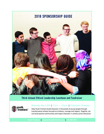
19munication of distributed control and real-time systems. CAN bus is widely used withsensors for data acquisition, industrial control systems and is an instrument with highreliability and flexibility. (Texas Instrument 2016.)2.1.1. The CAN BusRobert Bosch developed the automotive CAN Bus. It is a multi-master message broadcast system that gives a maximum signaling rate of 1 Megabit per second (Mbps). Automotive components use it to communicate on a single or dual-wire networked databus. CAN is a serial bus protocol used to connect individual systems and sensors and itis an alternative to conventional multi-wire looms. (Texas Instrument 2016.)CAN HighRCAN Bus LineRLLCAN LowFigure 1. CAN Bus Architecture (Github 2018).
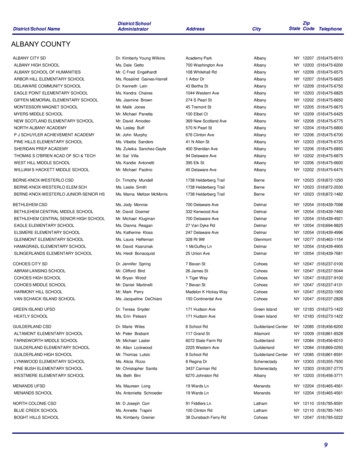
20Figure 1 shows the CAN Bus Architecture. The maximum signaling rate of 1Mbps isachieved with the High-Speed ISO11898 standard specifications having a bus length of40m and maximum of 30 nodes. The cable could be a shielded or unshielded twistedpair having a 120-Ω resistor at each end. This standard uses a single line of twisted-paircable as the network topology as presented in figure 1. A 120-Ω resistors is used to terminate both ends matching the characteristic impedance of the line to prevent signal reflections. Using RL on a node should be avoided based on the ISO 11898 because thenode will be disconnected from the bus and the bus lines would lose termination. (TexasInstrument 2016.)2.1.2. CAN StandardThe ISO 11898:2003 CAN communication protocol gives details on how information istransmitted from one device to another on a network and comply with the Open SystemInterconnect (OSI) model. The Open System Interconnect (OSI) model is defined interms of layer where the physical layer of the module defines the actual communicationbetween devices connected by the physical medium. The last two layers of the OSI/ISOmodel’s seven layers are defined by the ISO 11898 architecture as the data-link layerand the physical layers respectively as shown in figure 2. (Texas Instrument 2016.)Figure 2. ISO11898 Architecture (Github 2018).
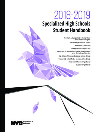
21Choosing between the Standard or Extended CANMessage Frames are used to transmit and receive data in the CAN system. The Messageframes carry data from a transmitting node to one, or more, receiving nodes. The Message Frame formats supported by CAN protocol are the Standard CAN (CAN 2.0A)which uses 11-bit identifiers and the Extended CAN (CAN 2.0B) which uses 29-bitidentifiers. The “standard” 11-bit identifier, providing 211 or 2048 different messageidentifiers and the “extended” 29-bit identifier, providing 229 or 537 million identifiers.However, both provide signaling rates from 125kbps to 1Mbps. (Texas Instrument2016.)Standard CAN (CAN 2.0A) 11-bit identifiers.Figure 3. CAN 2.0A - Standard CAN Frame 11-Bit Identifier.The standard CAN frame in figure 3 consists of the following bit fields: SOF – Start ofFrame, Identifier – the standard CAN 11-bit identifier , RTR – Remote TransmissionRequest (RTR), IDE – Identification extension (IDE), r0 – Reserved bit, DLC – datalength code, Data – allows up to 64bits (8bytes) of data to be sent, CRC – 16-bits (15bits plus delimiter) cyclic redundancy check (CRC) containing the checksum used forerror detection, ACK – Acknowledge bit, EOF – End of Frame bit has 7-bits and marksthe end of a CAN frame (message) and disables bit stuffing and IFS – 7-bits interframespace bit contains the time required by the controller to move a correctly received frameto its appropriate position in a message buffer area. (Texas Instrument 2016.)
22Extended CAN (CAN 2.0B) 29-bit identifiers.Figure 4. CAN 2.0B - Extended CAN Frame 29-Bit Identifier.The Extended CAN in figure 4 is the same as the standard CAN message in figure 3,however, the Extended CAN message has additional bit fields such as: SRR – Substituteremote request (SRR) bit. It replaces the RTR bit in the standard message location as aplaceholder in the extended format, IDE – When we have a recessive bit in the identifierextension (IDE), this implies that additional identifier bits follow the IDE of the 11-bitidentifier, that is, the 18-bit extension which follows the IDE. It is an additional reservebit included ahead of the DLC bit. (Texas Instrument 2016.)Most CAN 2.0A controllers transmit and receive only Standard format messages, although some (known as CAN 2.0B passive) will receive Extended format messages butthen ignore them. However, CAN 2.0B controllers can send and receive messages inboth formats. (Texas Instrument 2016.)The CAN Message Frame format used in this thesis was determined by the smart NOxsensor used. The smart NOx sensor has an Extended CAN ID of 0x18FEDF00.2.1.3. CAN MessagesCAN messages can be said to be contents-addressed, that is, the content of the messageimplicitly determines their address. The messages are short – maximum utility load of94 bits with no explicit address in the message. (Kvaser 2018a.)
23CAN transmits message signals on the CAN network using two wires, CAN-High andCAN-Low. In a scenario of several sensors (nodes) need to send their data, the CANbus implements a message priority identifier. The message with higher priority (lowerbinary message identifier number) wins the bus access. The bus access is a randomevent-driven process and if two nodes try to occupy the bus simultaneously, access isimplemented using a nondestructive, bit-wise arbitration. Nondestructive implies thatthe node that wins the bus access continues with its message transmission without themessage being destroyed or corrupted by the other nodes. The priority allocation featuremakes CAN to be attractive in its application to real-time control environment. (TexasInstrument 2016.)CAN controller uses an arbitration process to handle the message transmission priorityas each node continuously monitors its own transmissions. For example, in figure 5node B's recessive bit is overwritten by node C’s higher priority dominant bit and nodeB detects that the bus state does not match the bit that it transmitted, therefore it pausesits transmission allowing node C to continue with transmitting its message. Node B thenmakes another attempt to transmit its message when node C has completed its messagetransmission and the bus is free. This functionality is present entirely within the CANcontroller as it is part of the ISO 11898 physical signaling layer and it is completelytransparent to a CAN user. (Texas Instrument 2016.)Figure 5. Arbitration on a CAN Bus (Texas Instrument 2016).
24On a CAN bus, the CAN message/frames are of four types namely data frame, remoteframe, error frame, and overload frame. They are not discussed here in details as theyare not part of the scope of the research. (Kvaser 2018b.)The CAN Bus is a reliable and robust bus because of its error handling capability. TheCAN protocol uses five techniques of error checking. It uses three at the message leveland two at the bit level. A message that fails any one of these error detection techniquesis not accepted leading to the generation of an error frame from the receiving node.When this happens, the transmitting node is forced to retransmit the message until it isreceived correctly. However, for a faulty node that hangs up a bus when its continuouslyin error, its ability to transmit is disabled by its controller when an error limit is reached.2.2. Wireless Communication ProtocolsIn this chapter, some available wireless solutions being used to connect remote sensorsand devices to a central monitoring system are analyzed. These wireless solutions canbe applied in several areas, however, selecting the right solution and using it in the rightapplication is very crucial and can be a tough task having several associated risks.All wireless communication comprises of the following components; a transmitter, receiver, antennas, channel, and the environment. The transmitter sends signals to an antenna for transmission and the radio transmitter encodes data in RF waves having significant signal strength (power output) to transmit the signal to a receiver. The receivercollects and decodes the data arriving at the receiving antenna. At the receiver, assignedRF signals are received and decoded while discarding the unwanted signals. Differentradiation patterns are generated by antennas depending on their de
Figure 40. BLE-CAN receiver and Kvaser Leaf Light HS v2 USB 77 Figure 41. Hardware setup of Xbee-CAN bridge 78 Figure 42. Block diagram for the hardware setup of XBee-CAN bridge 79 Figure 43. Smart NOx sensor and XBee-CAN transmitter 80 Figure 44. XBee-CAN receiver and Kvaser Leaf Light HS v2 USB 81 Figure 45. Hardware setup of WIFI-CAN bridge 83