Transcription
XBee /XBee-PRO RF ModulesXBee /XBee-PRO RF ModulesRF Module OperationRF Module ConfigurationAppendicesProduct Manual v1.xEx - 802.15.4 ProtocolFor RF Module Part Numbers: XB24-A.-001, XBP24-A.-001IEEE 802.15.4 RF Modules by Digi InternationalDigi International Inc.11001 Bren Road EastMinnetonka, MN 55343877 912-3444 or 952 912-3444http://www.digi.com90000982 B2009.09.23
XBee /XBee‐PRO RF Modules ‐ 802.15.4 ‐ v1.xEx [2009.09.23] 2009 Digi International, Inc. All rights reservedThe contents of this manual may not be transmitted or reproduced in any form orby any means without the written permission of Digi, Inc.XBee and XBee‐PRO are registered trademarks of Digi, Inc.Technical Support:Phone:(866) 765-9885 toll-free U.S.A. & Canada(801) 765-9885 Worldwide8:00 am - 5:00 pm [U.S. Mountain Time]Live Chat:www.digi.comOnline .jspEmail:rf-experts@digi.com 2009 Digi International, Inc.ii
XBee /XBee‐PRO RF Modules ‐ 802.15.4 ‐ v1.xEx [2009.09.23]Contents1. XBee /XBee-PRO RF ModulesKey Features4SpecificationsUnited States (FCC)56FCC Notices7864Approved Antennas2. RF Module OperationSerial CommunicationsUART Data FlowAPI Operation10Japan6868Appendix B: Additional Information121-Year WarrantyADC and Digital I/O Line SupportI/O Data Format6868Labeling Requirements1111Flow ControlCanada (IC)6567Labeling Requirements1010Transparent Operation6969131314Sleep Support14DIO Pin Change Detect14Sample Rate (Interval)14I/O Line Passing15Configuration Example15XBee /XBee-PRO NetworksPeer-to-Peer1616NonBeacon (w/ Coordinator)1617XBee /XBee-PRO AddressingUnicast Mode2020Broadcast Mode20Modes of OperationIdle Mode64FCC-Approved Antennas (2.4 GHz)Electrical Characteristics6464OEM Labeling RequirementsMounting ConsiderationsAssociation5758Appendix A: Agency Certifications45Mechanical DrawingsAPI SupportAPI Frame SpecificationsAPI TypesWorldwide AcceptancePin Signals42121Transmit/Receive ModesSleep Mode2123Command Mode253. RF Module Configuration26Programming the RF ModuleProgramming Examples2626Remote Configuration CommandsSending a Remote Command27Applying Changes on Remote27Remote Command ResponsesCommand Reference TablesCommand DescriptionsAPI Operation2727273657 2009 Digi International, Inc.iii
1. XBee /XBee‐PRO RF ModulesThe XBee and XBee-PRO RF Modules were engineered tomeet IEEE 802.15.4 standards and support the uniqueneeds of low-cost, low-power wireless sensor networks.The modules require minimal power and provide reliabledelivery of data between devices.The modules operate within the ISM 2.4 GHz frequencyband and are pin-for-pin compatible with each other.Key FeaturesLong Range Data IntegrityXBeeLow PowerXBee Indoor/Urban: up to 100’ (30 m) TX Peak Current: 45 mA (@3.3 V) Outdoor line-of-sight: up to 300’ (90 m) RX Current: 50 mA (@3.3 V) Transmit Power: 1 mW (0 dBm) Power-down Current: 10 µA Receiver Sensitivity: -92 dBmXBee-PRO Indoor/Urban: up to 300’ (90 m), 200' (60m) for International variant Outdoor line-of-sight: up to 1 mile (1600m), 2500' (750 m) for International variant Transmit Power: 63mW (18dBm), 10mW(10dBm) for International variant Receiver Sensitivity: -100 dBmRF Data Rate: 250,000 bpsAdvanced Networking & SecurityRetries and AcknowledgementsXBee-PRO TX Peak Current: 250mA (150mA forinternational variant) TX Peak Current (RPSMA module only):340mA (180mA for international variant RX Current: 55 mA (@3.3 V) Power-down Current: 10 µAADC and I/O line supportAnalog-to-digital conversion, Digital I/OI/O Line PassingEasy-to-UseDSSS (Direct Sequence Spread Spectrum)No configuration necessary for out-of boxRF communicationsEach direct sequence channels has over65,000 unique network addresses availableFree X-CTU Software(Testing and configuration software)Source/Destination AddressingAT and API Command Modes forconfiguring module parametersUnicast & Broadcast CommunicationsPoint-to-point, point-to-multipointand peer-to-peer topologies supportedExtensive command setSmall form factorWorldwide AcceptanceFCC Approval (USA) Refer to Appendix A [p64] for FCC Requirements.Systems that contain XBee /XBee-PRO RF Modules inherit Digi Certifications.ISM (Industrial, Scientific & Medical) 2.4 GHz frequency bandManufactured under ISO 9001:2000 registered standardsXBee /XBee-PRO RF Modules are optimized for use in the United States, Canada, Australia,Japan, and Europe. Contact Digi for complete list of government agency approvals. 2009 Digi International Inc.4
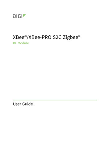
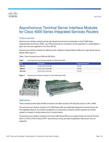
XBee /XBee‐PRO RF Modules ‐ 802.15.4 ‐ v1.xEx [2009.09.23]SpecificationsTable 1‐01.Specifications of the XBee /XBee‐PRO RF ModulesSpecificationXBeeXBee-PROIndoor/Urban RangeUp to 100 ft (30 m)Up to 300 ft. (90 m), up to 200 ft (60 m) InternationalvariantOutdoor RF line-of-sight RangeUp to 300 ft (90 m)Up to 1 mile (1600 m), up to 2500 ft (750 m)international variantTransmit Power Output(software selectable)1mW (0 dBm)63mW (18dBm)*10mW (10 dBm) for International variantRF Data Rate250,000 bps250,000 bpsSerial Interface Data Rate(software selectable)1200 bps - 250 kbps(non-standard baud rates also supported)1200 bps - 250 kbps(non-standard baud rates also supported)Receiver Sensitivity-92 dBm (1% packet error rate)-100 dBm (1% packet error rate)Supply Voltage2.8 – 3.4 V2.8 – 3.4 VTransmit Current (typical)45mA (@ 3.3 V)250mA (@3.3 V) (150mA for international variant)RPSMA module only: 340mA (@3.3 V) (180mA forinternational variant)Idle / Receive Current (typical)50mA (@ 3.3 V)55mA (@ 3.3 V)Power-down Current 10 µA 10 µAOperating FrequencyISM 2.4 GHzISM 2.4 GHzDimensions0.960” x 1.087” (2.438cm x 2.761cm)0.960” x 1.297” (2.438cm x 3.294cm)Operating Temperature-40 to 85º C (industrial)-40 to 85º C (industrial)Antenna OptionsIntegrated Whip, Chip or U.FL Connector, RPSMAConnectorIntegrated Whip, Chip or U.FL Connector, RPSMAConnectorPerformancePower RequirementsGeneralNetworking & SecuritySupported Network TopologiesPoint-to-point, Point-to-multipoint & Peer-to-peerNumber of Channels(software selectable)16 Direct Sequence Channels12 Direct Sequence ChannelsAddressing OptionsPAN ID, Channel and AddressesPAN ID, Channel and AddressesUnited States (FCC Part 15.247)OUR-XBEEOUR-XBEEPROIndustry Canada (IC)4214A XBEE4214A XBEEPROEurope (CE)ETSIETSI (Max. 10 dBm transmit power output)*JapanR201WW07215214R201WW08215111 (Max. 10 dBm transmit poweroutput)*AustrailaC-TickC-TickAgency Approvals* See Appendix A for region‐specific certification requirements.Antenna Options: The ranges specified are typical when using the integrated Whip (1.5 dBi) and Dipole (2.1 dBi) antennas. The Chip antenna option provides advantages in its form factor; however, it typically yields shorter range than theWhip and Dipole antenna options when transmitting outdoors.For more information, refer to the "XBee Antennas" Knowledgebase Article located on Digi's Support Web siteMechanical DrawingsFigure 1‐01. Mechanical drawings of the XBee /XBee‐PRO RF Modules (antenna options not shown) 2009 Digi Internatonal, Inc.5
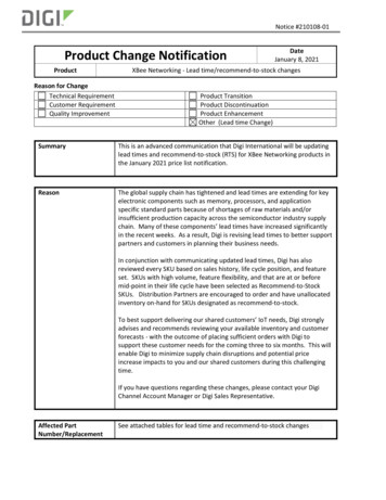
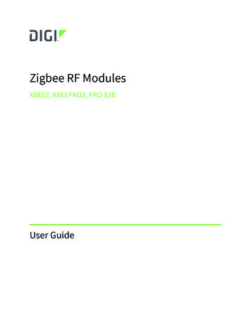
XBee /XBee‐PRO RF Modules ‐ 802.15.4 ‐ v1.xEx [2009.09.23]The XBee and XBee‐PRO RF Modules are pin‐for‐pin compatible.Mounting ConsiderationsThe XBee /XBee-PRO RF Module was designed to mount into a receptacle (socket) and therefore does not require any soldering when mounting it to a board. The XBee Development Kits contain RS-232 and USB interface boards which use two 20-pin receptacles to receive modules.Figure 1‐02. XBee Module Mounting to an RS‐232 Interface Board.The receptacles used on Digi development boards are manufactured by Century Interconnect.Several other manufacturers provide comparable mounting solutions; however, Digi currently usesthe following receptacles: Through-hole single-row receptacles Samtec P/N: MMS-110-01-L-SV (or equivalent) Surface-mount double-row receptacles Century Interconnect P/N: CPRMSL20-D-0-1 (or equivalent) Surface-mount single-row receptacles Samtec P/N: SMM-110-02-SM-SDigi also recommends printing an outline of the module on the board to indicate the orientation themodule should be mounted. 2009 Digi Internatonal, Inc.6
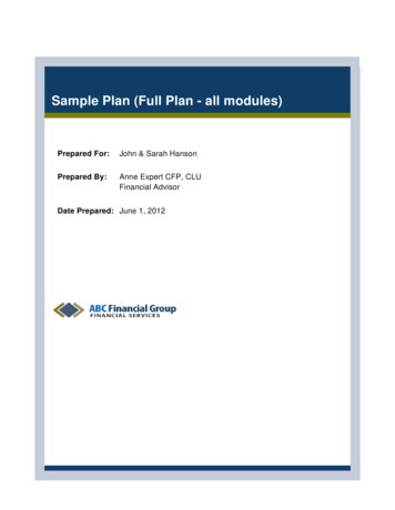
XBee /XBee‐PRO RF Modules ‐ 802.15.4 ‐ v1.xEx [2009.09.23]Pin SignalsFigure 1‐03. XBee /XBee‐PRO RF Module PinNumbers(top sides shown ‐ shields on bottom)Table 1‐02.Pin 1Pin 20Pin 10Pin 11Pin 1Pin 20Pin 10Pin 11Pin Assignments for the XBee and XBee‐PRO Modules(Low‐asserted signals are distinguished with a horizontal line above signal name.)Pin #NameDirection1VCC-DescriptionPower supply2DOUTOutputUART Data Out3DIN / CONFIGInputUART Data In4DO8*OutputDigital Output 85RESETInputModule Reset (reset pulse must be at least 200 ns)6PWM0 / RSSIOutputPWM Output 0 / RX Signal Strength Indicator7PWM1OutputPWM Output 18[reserved]-Do not connectPin Sleep Control Line or Digital Input 89DTR / SLEEP RQ / DI8Input10GND-Ground11AD4 / DIO4EitherAnalog Input 4 or Digital I/O 412CTS / DIO7EitherClear-to-Send Flow Control or Digital I/O 713ON / SLEEPOutputModule Status Indicator14VREFInputVoltage Reference for A/D Inputs15Associate / AD5 / DIO5EitherAssociated Indicator, Analog Input 5 or Digital I/O 516RTS / AD6 / DIO6EitherRequest-to-Send Flow Control, Analog Input 6 or Digital I/O 617AD3 / DIO3EitherAnalog Input 3 or Digital I/O 318AD2 / DIO2EitherAnalog Input 2 or Digital I/O 219AD1 / DIO1EitherAnalog Input 1 or Digital I/O 120AD0 / DIO0EitherAnalog Input 0 or Digital I/O 0* Function is not supported at the time of this releaseDesign Notes: Minimum connections: VCC, GND, DOUT & DIN Minimum connections for updating firmware: VCC, GND, DIN, DOUT, RTS & DTR Signal Direction is specified with respect to the module Module includes a 50k Ω pull-up resistor attached to RESET Several of the input pull-ups can be configured using the PR command Unused pins should be left disconnected 2009 Digi Internatonal, Inc.7
XBee /XBee‐PRO RF Modules ‐ 802.15.4 ‐ v1.xEx [2009.09.23]Electrical CharacteristicsTable 1‐03.DC Characteristics (VCC 2.8 ‐ 3.4 ionMinTypicalMaxUnitInput Low VoltageInput High VoltageOutput Low VoltageOutput High VoltageInput Leakage CurrentHigh Impedance Leakage CurrentAll Digital InputsAll Digital InputsIOL 2 mA, VCC 2.7 VIOH -2 mA, VCC 2.7 VVIN VCC or GND, all inputs, per pinVIN VCC or GND, all I/O High-Z, per pin0.7 * VCCVCC - 0.5-0.35 * VCC0.511VVVVµAµATXTransmit CurrentVCC 3.3 V--mARXReceive CurrentVCC 3.3 V--mAPWR-DWNPower-down CurrentSM parameter 1-0.0250.025215, 14045(PRO,(XBee)Int)5055(XBee)(PRO) 10-µATable 1‐04.SymbolADC Characteristics (Operating)VREFHCharacteristicVREF - Analog-to-Digital converterreference rangeIREFVREF - Reference Supply CurrentVINDCAnalog Input Voltage1ConditionEnabledDisabled or Sleep ModeMinTypicalMaxUnit2.08-VDDAD*VVSSAD - 0.3200 0.01-0.02VDDAD 0.3µAµAVUnit1. Maximum electrical operating range, not valid conversion range.* VDDAD is connected to VCC.Table 1‐05.ADC Timing/Performance ASSource Impedance at Input2Condition--10VAINAnalog Input Voltage3VREFLRESIdeal Resolution (1 LSB)4DNLDifferential Non-linearity5INLEZSIntegral Non-linearity6- 0.5 1.0LSBZero-scale Error7- 0.4 1.0LSBFFSFull-scale Error8- 0.4 1.0LSBEILInput Leakage Error9- 0.05 5.0LSBETUTotal Unadjusted Error10- 1.1 2.5LSB2.08V VDDAD 3.6VVREFHkV2.031-3.516mV- 0.5 1.0LSB1. All ACCURACY numbers are based on processor and system being in WAIT state (very little activity and no IO switching)and that adequate low‐pass filtering is present on analog input pins (filter with 0.01 μF to 0.1 μF capacitor between analoginput and VREFL). Failure to observe these guidelines may result in system or microcontroller noise causing accuracy errorswhich will vary based on board layout and the type and magnitude of the activity.Data transmission and reception during data conversion may cause some degradation of these specifications, depending onthe number and timing of packets. It is advisable to test the ADCs in your installation if best accuracy is required.2. RAS is the real portion of the impedance of the network driving the analog input pin. Values greater than this amount maynot fully charge the input circuitry of the ATD resulting in accuracy error.3. Analog input must be between VREFL and VREFH for valid conversion. Values greater than VREFH will convert to 3FF.4. The resolution is the ideal step size or 1LSB (VREFH–VREFL)/10245. Differential non‐linearity is the difference between the current code width and the ideal code width (1LSB). The currentcode width is the difference in the transition voltages to and from the current code.6. Integral non‐linearity is the difference between the transition voltage to the current code and the adjusted ideal transitionvoltage for the current code. The adjusted ideal transition voltage is (Current Code–1/2)*(1/((VREFH EFS)–(VREFL EZS))).7. Zero‐scale error is the difference between the transition to the first valid code and the ideal transition to that code. TheIdeal transition voltage to a given code is (Code–1/2)*(1/(VREFH–VREFL)).8. Full‐scale error is the difference between the transition to the last valid code and the ideal transition to that code. The idealtransition voltage to a given code is (Code–1/2)*(1/(VREFH–VREFL)).9. Input leakage error is error due to input leakage across the real portion of the impedance of the network driving the analogpin. Reducing the impedance of the network reduces this error. 2009 Digi Internatonal, Inc.8
XBee /XBee‐PRO RF Modules ‐ 802.15.4 ‐ v1.xEx [2009.09.23]10. Total unadjusted error is the difference between the transition voltage to the current code and the ideal straight‐line trans‐fer function. This measure of error includes inherent quantization error (1/2LSB) and circuit error (differential, integral, zero‐scale, and full‐scale) error. The specified value of ETU assumes zero EIL (no leakage or zero real source impedance). 2009 Digi Inter
1. XBee /XBee‐PRO RF Modules The XBee and XBee-PRO RF Modules were engineered to meet IEEE 802.15.4 standards and support the unique needs of low-cost, low-power wireless sensor networks. The modules require minimal power and provide reliable delivery of data between devices. The modules operate within the ISM 2.4 GHz frequency