Transcription
XBee /XBee-PRO S2C ZigBee RF ModuleUser Guide
Revision history—90002002Revision DateDescriptionSMay 2015Update the SMT dimensions drawing. Added a section on deep sleep andsleep current measurements. Updated the baud rates supported by the BDcommand. Updated the Brazil ANATEL certification information.TJuly 2015Revised the Maximum RF payload size section. Frames 0x90 and 0x91 nolonger report the 0x40 indicator - removed it.UDecember Updated XBee-PRO Surface Mount agency approvals. Added missing2015Extended Modem Status status code descriptions to the 0x98 frame. AddedANATEL labels.VJuly 2016Updated the firmware release notes section. Updated several hardwarespecifications with S2D hardware information. Updated regulatoryinformation. Revised the Programmable XBee SDK section. Added the EDcommand. Updated the BD command. Added antennas for the S2Dhardware. Added a section on loading ZB firmware. Added “S2C” to theproduct name on the title page and throughout the document. Updated thenumber of supported address table entries.Trademarks and copyrightDigi, Digi International, and the Digi logo are trademarks or registered trademarks in the UnitedStates and other countries worldwide. All other trademarks mentioned in this document are theproperty of their respective owners. 2016 Digi International Inc. All rights reserved.DisclaimersInformation in this document is subject to change without notice and does not represent acommitment on the part of Digi International. Digi provides this document “as is,” without warranty ofany kind, expressed or implied, including, but not limited to, the implied warranties of fitness ormerchantability for a particular purpose. Digi may make improvements and/or changes in this manualor in the product(s) and/or the program(s) described in this manual at any time.WarrantyTo view product warranty information, go to the following website:http://www.digi.com/howtobuy/termsSend commentsDocumentation feedback: To provide feedback on this document, send your comments totechcomm@digi.com.XBee/XBee-PRO S2C ZigBee RF Module2
Customer supportDigi Technical Support: Digi offers multiple technical support plans and service packages to help ourcustomers get the most out of their Digi product. For information on Technical Support plans andpricing, contact us at 877.912.3444 or visit us at www.digi.com/support.Online: www.digi.com/support/eserviceXBee/XBee-PRO S2C ZigBee RF Module3
ContentsXBee/XBee-PRO S2C ZigBee RF ModuleApplicable firmware and hardwareFirmware release notes1414Technical specificationsPerformance specificationsPower requirementsGeneral specificationsNetworking and security specificationsInterface optionsAgency approvalsSerial communication specificationsUART pin assignmentsSPI pin assignmentsGPIO specificationsHardware specifications for the programmable variantMechanical drawingsPin signals for the surface-mount modulePin signals for the through-hole moduleEM357 pin mappingsDesign notesPower supply designBoard layoutAntenna performanceRecommended pin connectionsDesign notes for PCB antenna devicesDesign notes for SMT RF pad devicesModule operation for the programmable variantProgrammable XBee SDKProgrammable 72729323233XBee/XBee-PRO S2C ZigBee RF Module OperationSerial interfaceUART data flowSerial dataSPI communicationsSPI operationSerial port selectionSerial buffersSerial receive bufferSerial transmit bufferXBee/XBee-PRO S2C ZigBee RF Module3636363737383838394
UART flow controlCTS flow controlRTS flow controlBreak controlSerial interface protocolsTransparent operationAPI operationCompare transparent and API operationModes of operationIdle modeTransmit modeReceive modeCommand modeSleep Mode3939394040404041424343444445ZigBee networksIntroduction to XBee devicesZigBee stack layersZigBee networking conceptsDevice typesPAN IDOperating channelsZigbee application layers: in depthApplication Support Sublayer (APS)Application profilesZigBee coordinator operationForming a networkSecurity policyChannel selectionPAN ID selectionPersistent dataXBee ZigBee coordinator startupPermit joiningResetting the coordinatorLeaving a networkReplacing a coordinator (security disabled only)Example: starting a coordinatorExample: replacing a coordinator (security disabled)ZigBee router operationDiscovering ZigBee networksJoining a networkPersistent dataZigBee router joiningPermit joiningRouter network connectivityEnd device operationDiscovering ZigBee networksJoining a networkEnd device capacityPersistent dataOrphan scansEnd device joiningParent connectivityResetting the end deviceXBee/XBee-PRO S2C ZigBee RF 585858595960606364646465656566665
Leaving a networkExample: joining a networkZigBee channel scanningManaging multiple ZigBee networksPAN ID filteringPre-configured security keysPermit joiningApplication messaging6767686868686869Transmission, addressing, and routingAddressing64-bit device addresses16-bit device addressesApplication layer addressingData transmissionBroadcast transmissionsUnicast transmissionsAddress resolutionAddress tableGroup tableBinding transmissionsAddress resolutionBinding tableMulticast transmissionsAddress resolutionFragmentationData transmission examplesAT firmwareAPI firmwareAPI frameRF packet routingLink status transmissionAODV mesh routingMany-to-One routingHigh/Low RAM Concentrator modeSource routingEncrypted transmissionsMaximum RF payload sizeThroughputLatency timing specificationsZDO transmissionsZDOSending a ZDO commandReceiving ZDO command and responsesTransmission timeoutsUnicast timeoutExtended timeoutTransmission 7879828282878789909090909193939494ZigBee securitySecurity modesZigBee security modelXBee/XBee-PRO S2C ZigBee RF Module98986
Network layer securityAPS layer securityTrust centerForming or joining a secure networkImplementing security on the XBeeEnabling securitySetting the network security keySetting the APS Trust Center Link KeyEnable APS encryptionUse a trust centerXBee security examples9899101101101102102102102103103Network commissioning and diagnosticsDevice placementDevice discoveryNetwork discoveryZDO discoveryJoining AnnounceCommissioning pushbutton and associate LEDCommissioning pushbuttonAssociate LEDBindingGroup Table API106106106106106106107108109111Managing End DevicesEnd Device operationParent operationEnd Device poll timeoutsPacket buffer usageNon-Parent device operationXBee End Device configurationPin sleepCyclic sleepRecommended sleep current measurementsAchieve the lowest sleep currentCompensate for switching timeInternal pin pull-upsTransmitting RF dataReceiving RF dataI/O samplingWaking end devices with the Commissioning PushbuttonParent verificationRejoiningRouter/Coordinator configurationRF packet buffering timeoutChild poll timeoutTransmission timeoutPutting it all togetherShort sleep periodsExtended sleep periodsSleep examplesXBee/XBee-PRO S2C ZigBee RF 31331331331341341341351361361361367
Analog and digital I/O linesConfigurable I/O pins and configuration commandsXBee ZB through-hole RF moduleI/O ConfigurationI/O samplingQueried samplingPeriodic I/O samplingChange detection samplingRSSI PWMI/O examplesPWM1139139140141142143143143144144API OperationAPI frame formatAPI operation (AP parameter 1)API operation-with escaped characters (AP parameter 2)LengthFrame dataCalculate and verify checksumsAPI examplesAPI serial port exchangesAT commandsTransmit and Receive RF dataRemote AT commandsSource routingFrame descriptionsAT Command frame - 0x08AT Command - Queue Parameter Value frame - 0x09Transmit Request frame - 0x10Explicit Addressing Command frame - 0x11Remote AT Command Request frame - 0x17Create Source Route - 0x21AT Command Response frame - 0x88Modem Status frame - 0x8ATransmit Status frame - 0x8BReceive Packet frame - 0x90Explicit Rx Indicator frame - 0x91Data Sample Rx Indicator frame - 0x92XBee Sensor Read Indicator - 0x94Node Identification Indicator frame - 0x95Remote Command Response frame - 0x97Extended Modem Status frame - 0x98Over-the-Air Firmware Update Status - 0xA0Route Record Indicator - 0xA1Many-to-One Route Request Indicator - 0xA3Send ZigBee Device Objects (ZDO) commands with the APIExampleSend ZigBee Cluster Library (ZCL) commands with the APIExampleSend Public Profile Commands with the APIFrame specific dataExampleXBee/XBee-PRO S2C ZigBee RF 971982002012042072072108
AT commandsAddressing commandsDH (Destination Address High)DL (Destination Address Low)MY (16-bit Network Address)MP (16-bit Parent Network Address)NC (Number of Remaining Children)SH (Serial Number High)SL (Serial Number Low)NI (Node Identifier)SE (Source Endpoint)DE (Destination Endpoint)CI (Cluster ID)TO (Transmit Options)NP (Maximum Packet Payload Bytes)DD (Device Type Identifier)CR (Conflict Report)Network commandsCH (Operating Channel)CE (Coordinator Enable)ID (Extended PAN ID)OP (Operating Extended PAN ID)NH (Maximum Unicast Hops)BH (Broadcast Hops)OI (Operating 16-bit PAN ID)NT (Node Discover Timeout)NO (Network Discovery Options)SC (Scan Channels)SD (Scan Duration)ED (Energy Detect)ZS (ZigBee Stack Profile)NJ (Node Join Time)JV (Channel Verification)NW (Network Watchdog Timeout)JN (Join Notification)AR (Aggregate Routing Notification)Security commandsEE (Encryption Enable)EO (Encryption Options)NK (Network Encryption Key)KY (Link Key)RF interfacing commandsPL (TX Power Level)PM (Power Mode)DB (Received Signal Strength)PP (Peak Power)Serial interfacing commandsAP (API Enable)AO (API Options)BD (Interface Data Rate)NB (Parity)SB (Stop Bits)RO (Packetization Timeout)D7 (DIO7/CTS)XBee/XBee-PRO S2C ZigBee RF 2282292292302309
D6 (DIO6/RTS)I/O settings commandsIR (I/O Sample Rate)IC (Digital Change Detection)P0 (RSSI/PWM0 Configuration)P1 (DIO11/PWM1 Configuration)P2 (DIO12 Configuration)P3 (DIO13/DOUT Configuration)P4 (DIO14/DIN)P5 (DIO15/SPI MISO)P6 (DIO16/SPI MOSI)P7 (DIO17/SPI SSEL )P8 (DIO18/SPI SCLK)P9 (DIO19/SPI ATTN/PTI DATA)D0 (AD0/DIO0 Configuration)D1 (AD1/DIO1/PTI En Configuration)D2 (AD2/DIO2 Configuration)D3 (AD3/DIO3 Configuration)D4 (DIO4 Configuration)D5 (DIO5/Associate Configuration)D8 (DIO8/DTR/SLP RQ)D9 (DIO9/ON SLEEP)LT (Associate LED Blink Time)PR (Pull-up/Down Resistor Enable)PD (Pull Up/Down Direction)RP (RSSI PWM Timer)DC (Device Controls)DO (Device Options)%V (Voltage Supply Monitoring)V (Voltage Supply Monitoring)Diagnostic commandsVR (Firmware Version)VL (Version Long)HV (Hardware Version)AI (Association Indication)Command mode optionsCT (Command Mode Timeout)CN (Exit Command mode)GT (Guard Times)CC (Command Character)Sleep commandsSM (Sleep Mode)SN (Number of Cycles Between ON SLEEP )SP (Sleep Period)ST (Time before Sleep)SO (Sleep Options)WH (Wake Host Delay)PO (Polling Rate)Execution commandsAC (Apply Changes)AS (Active Scan)WR (Write)RE (Restore Defaults)FR (Software Reset)NR (Network Reset)XBee/XBee-PRO S2C ZigBee RF 24824824824824924924910
SI (Sleep Immediately)CB (Commissioning Pushbutton)&X (Clear Binding and Group Tables)ND (Node Discovery)DN (Destination Node)IS (Force Sample)249250250250251252Module supportXCTU configuration toolCustomizing XBee ZigBee firmwareDesign considerations for Digi drop-in networkingXBee BootloaderProgramming XBee modulesSerial firmware updatesInvoke the XBee BootloaderSend a firmware imageWriting custom firmwareRegulatory complianceEnabling GPIO 1 and 2Detecting XBee versus XBee-PROSpecial instructions for using the JTAG rtificationsUnited States (FCC)OEM labeling requirementsFCC noticesFCC-approved antennas (2.4 GHz)Associated antenna descriptionsRF exposureEuropeOEM labeling requirementsDeclarations of conformityAntennasIC (Industry Canada) CertificationLabeling requirementsFor XBee ZB surface mount:For XBee-PRO ZB surface mount:For XBee ZB through-hole:For XBee-PRO ZB through-hole:Transmitters for detachable antennasDetachable antennaFor XBee S2D SMT:RF ExposureAustralia (RCM)ANATEL (Brazil) 79280280280280280280281281282Migrating from XBee through-hole to XBee surface-mount devicesPin mappingMountingXBee/XBee-PRO S2C ZigBee RF Module28628711
Manufacturing informationRecommended solder reflow cycleRecommended footprintFlux and cleaningReworking290290292292Load ZB firmware on 802.15.4 devicesBackgroundLoad ZB firmware294295DefinitionsZigBee node typesZigBee protocolXBee/XBee-PRO S2C ZigBee RF Module29629712
XBee/XBee-PRO S2C ZigBee RF ModuleThis manual describes the operation of the XBee/XBee-PRO ZigBee RF Module, which consists ofZigBee firmware loaded onto XBee S2C and PRO S2C hardware.The XBee/XBee-PRO S2C ZigBee RF Modules provide wireless connectivity to end-point devices inZigBee mesh networks. Using the ZigBee PRO Feature Set, these modules are inter-operable withother ZigBee devices, including devices from other vendors. With the XBee, users can have theirZigBee network up-and-running in a matter of minutes without configuration or additionaldevelopment.The XBee/XBee-PRO S2C ZigBee RF Modules are compatible with other devices that use XBee ZigBeetechnology. These include ConnectPortX gateways, XBee and XBee-PRO Adapters, Wall Routers, XBeeSensors, and other products with the ZB name.Applicable firmware and hardwareFirmware release notesXBee/XBee-PRO S2C ZigBee RF Module141413
XBee/XBee-PRO S2C ZigBee RF ModuleApplicable firmware and hardwareApplicable firmware and hardwareHardware: S2CFirmware: 401x, 402x, 403x, 404x, 405xHardware: S2DFirmware: 705xFirmware release notesYou can view the current release notes in the Firmware Explorer section of XCTU. For instructions ondownloading and using XCTU, go to: usoftware/xctu.XBee/XBee-PRO S2C ZigBee RF Module14
Technical specificationsPerformance specificationsPower requirementsGeneral specificationsNetworking and security specificationsInterface optionsAgency approvalsSerial communication specificationsGPIO specificationsHardware specifications for the programmable variantMechanical drawingsPin signals for the surface-mount modulePin signals for the through-hole moduleEM357 pin mappingsDesign notesProgrammable XBee SDKXBee/XBee-PRO S2C ZigBee RF Module16161617171718192020222324253215
Technical specificationsPerformance specificationsPerformance specificationsThis table describes the performance specifications for the devices.XBee-PROZigBee S2C XBee ZigBee S2DSpecificationXBee ZigBee S2CIndoor/urbanrangeUp to 200 ft. (60 m)Up to 300ft. (90 m)Up to 200 ft. (60m)Outdoor RF lineof-sight rangeUp to 4000 ft. (1200 m)Up to 2miles (3200m)Up to 4000 ft. (1200m)63mW ( 18dBm)6.3 mW ( 8 dBm) Channel26 max power is 1 dBm-101 dBm-102 dBm, boost mode-100 dBm, normal modeTransmit power6.3mW ( 8 dBm), boost modeoutput (maximum) 3.1mW ( 5 dBm), normal modeChannel 26 max power is 3dBmRF data rate250,000 b/sReceiversensitivity-102 dBm, boost mode-100 dBm, normal modePower requirementsThe following table describes the power requirements for the devices.XBee-PRO ZigBee XBeeS2CZigBee S2DSpecificationXBee ZigBee S2CAdjustable powerYesSupply voltage2.1 - 3.6 V 2.2 - 3.6 V for programmableversion2.7 - 3.6 V2.1 - 3.6 VOperating current(transmit)45 mA ( 8 dBm, boost mode) 33 mA ( 5dBm, normal mode)120 mA @ 3.3 V, 18 dBm45 mAOperating current(receive)31 mA (boost mode)28 mA (normal mode)31 mA31 mAPower-downcurrent 1 µA @ 25 C 3 uA @ 25 CGeneral specificationsThe following table describes the general specifications for the devices.XBee/XBee-PRO S2C ZigBee RF Module16
Technical specificationsSpecificationNetworking and security specificationsXBee ZigBee S2CXBee-PRO ZigBee S2CXBee ZigBee S2DOperating frequency ISM 2.4 - 2.5 GHzbandForm factorthrough-hole, surface-mountsurface-mountDimensionsthrough-hole: 0.960 x1.087 in (2.438 x 2.761cm)surface-mount: 0.866 x1.33 x 0.120 in (2.199 x3.4 x 0.305 cm)surface-mount: 0.866 x1.33 x 0.120 in (2.199 x3.4 x 0.305 cm)Operatingtemperature-40 to 85 C (industrial)Antenna optionsthrough-hole: PCB antenna, U.FL connector, RPSMA connector, or integratedwiresurface-mount: RF pad, PCB antenna, or U.FL connectorthrough-hole: 0.960 x1.297 in (2.438 x 3.294cm)surface-mount: 0.866 x1.33 x 0.120 in (2.199 x3.4 x 0.305 cm)Networking and security specificationsThe following table describes the networking and security specifications for the devices.SpecificationXBee ZigBee S2CSupported networktopologiespoint-to-point, point-to-multipoint, peer-to-peer, and DigiMeshNumber of channels16 Direct sequencechannelsInterface immunityDSSS (Direct Sequence Spread Spectrum)Channels11 to 26Addressing optionsPAN ID and addresses, cluster IDs and endpoints (optional)XBee-PRO ZigBee S2C XBee ZigBee S2D15 Direct sequencechannels16 Direct sequencechannelsInterface optionsThe following table describes the interface options for the devices.Interface OptionsUART1 Mb/s maximum (burst)SPI5 Mb/s maximum (burst)Agency approvalsThis table describes the agency approvals for the devices.XBee/XBee-PRO S2C ZigBee RF Module17
Technical specificationsSerial communication specificationsNote Legacy XBee-PRO SMT (model: PRO S2C; hardware version 21xx) has different FCC and IC IDs.For more information, see Certifications.XBeeXBee-PRO(Through- (Throughhole)hole)XBee S2D(Surfacemount)FCC ID:MCQS2CTHFCC ID:MCQS2DSMApprovalXBee (Surfacemount)XBee-PRO(Surface-mount)United States (FCCPart 15.247)FCC ID: MCQXBS2CFCC ID: MCQXBPS2C (revisionK and earlier)FCC ID: MCQPS2CSM (revisionL and later)Industry Canada(IC)IC: 1846A-XBS2CIC: 1846A-XBPS2C IC: 1846A- IC: 1846A(revision K andS2CTHPS2CTHearlier)IC: 1846A-PS2CSM(revision L andlater)IC: 1846AS2DSMFCC/IC TestTransmit PowerOutput range-26 to 8 dBm-0.7 to 19.4 dBm-10 to 8dBmEurope (CE)YesAustraliaRCMJapanR201WW10215369Brazil (Res. 506)ANATEL: 0616-151209RoHSCompliant-26 to 8dBmFCC ID:MCQPS2CTH 1 to 19dBmYesRCMRCMYesRCMR210105563ANATEL: ial communication specificationsXBee RF modules support both Universal Asynchronous Receiver / Transmitter (UART) and SerialPeripheral Interface (SPI) serial connections.UART pin assignmentsSpecificationsDevice pin numberUART pinsXBee (surface-mount)XBee (through-hole)DOUT32DIN / CONFIG43XBee/XBee-PRO S2C ZigBee RF Module18
Technical specificationsGPIO specificationsSpecificationsDevice pin numberUART pinsXBee (surface-mount)XBee (through-hole)CTS / DIO72512RTS/ DIO62916For more information on UART operation, see XBee/XBee-PRO S2C ZigBee RF Module Operation.SPI pin assignmentsThe SC2 (Serial Communication Port 2) of the Ember 357 is connected to the SPI port.SpecificationsDevice pin numberSPI pinsXBee (surface mount)XBee (through-hole)SPI SCLK1418SPI SSEL1517SPI MOSI1611SPI MISO174For more information on SPI operation, see SPI operation.GPIO specificationsXBee RF modules have 15 General Purpose Input / Output (GPIO) ports available. The exact list willdepend on the module configuration, as some GPIO pads are used for purposes such as serialcommunication.See Enabling GPIO 1 and 2 for more information on configuring and using GPIO ports.GPIO electrical specificationValueVoltage - supply2.1 - 3.6 VLow Schmitt switching threshold0.42 - 0.5 x VCCHigh Schmitt switching threshold0.62 - 0.8 x VCCInput current for logic 0-0.5 µAInput current for logic 10.5 µAInput pull-up resistor value29 kΩInput pull-down resistor value29 kΩOutput voltage for logic 00.18 x VCC(maximum)XBee/XBee-PRO S2C ZigBee RF Module19
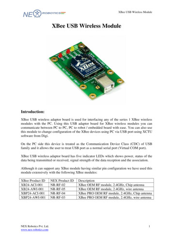
Technical specificationsHardware specifications for the programmable variantGPIO electrical specificationValueOutput voltage for logic 10.82 x VCC(minimum)Output source/sink current for pad numbers 3, 4, 5, 10, 12, 14, 15, 16, 17, 25, 26,28, 29, 30, and 32 on the SMT modules4 mAOutput source/sink current for pin numbers 2, 3, 4, 9, 12, 13, 15, 16, 17, and 19 onthe TH modules4 mAOutput source/sink current for pad numbers 7, 8, 24, 31, and 33 on the SMTmodules8 mAOutput source/sink current for pin numbers 6, 7, 11, 18, and 20 on the TH modules8 mATotal output current (for GPIO pads)40 mAHardware specifications for the programmable variantIf the module has the programmable secondary processor, add the following table values to thespecifications listed. For example, if the secondary processor is running at 20 MHz and the primaryprocessor is in receive mode then the new current value will be Itotal Ir2 Irx 14 mA 9 mA 23 mA,where Ir2 is the runtime current of the secondary processor andis the receive current of theprimary.Optional secondary processorspecificationAdd to specifications (Add to RX, TX, and sleepcurrents depending on mode of operation)Runtime current for 32 k running at 20MHz 14 mARuntime current for 32 k running at 1MHz 1 mASleep current 0.5 µA typicalFor additional specifications seeFreescale Datasheet and ManualMC9S08QE32Minimum Reset low pulse time forEM357 26 µSVREF Range1.8 VDC to VCCMechanical drawingsThe following mechanical drawings of the XBee/XBee-PRO S2C ZigBee RF Modules show alldimensions in inches. The first drawing shows the surface-mount model (antenna options not shown).XBee/XBee-PRO S2C ZigBee RF Module20
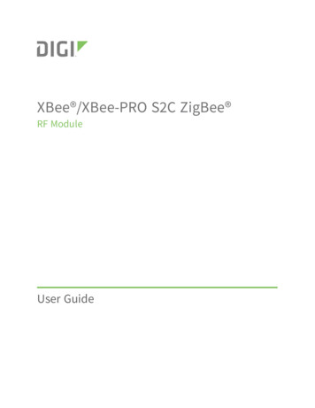
Technical specificationsMechanical drawingsThe drawings below show the XBee-PRO through-hole model.XBee/XBee-PRO S2C ZigBee RF Module21
Technical specificationsPin signals for the surface-mount modulePin signals for the surface-mount moduleThe following table shows the pin signals and their descriptions for the surface-mount D--Ground2VCC--PowerSupply3DOUT /DIO13BothOutputUART Data Out /GPIO4DIN / CONFIG /DIO14BothInputUART Data In /GPIO5DIO12BothGPIO6RESETInputModule Reset7RSSI PWM/DIO10BothOutputRX Signal Strength Indicator /GPIO8PWM1/DIO11BothDisabledPulse Width Modulator/GPIO9[reserved]-DisabledDo Not Connect10DTR/SLEEP RQ /DIO8BothInputPin Sleep Control Line/GPIO11GND--Ground12SPI ATTN/BOOTMODE/DIO19OutputOutputSerial Peripheral Interface AttentionDo not tie low on reset13GND--Ground14SPI CLK /DIO18InputInputSerial Peripheral InterfaceClock/GPIO15SPI SSEL/DIO17InputInputSerial Peripheral Interface notSelect/GPIO16SPI MOSI/DIO16InputInputSerial Peripheral Interface DataIn/GPIO17SPI MISO/DIO15OutputOutputSerial Peripheral Interface DataOut/GPIO18[reserved]*-DisabledDo not connect19[reserved]*-DisabledDo not connect20[reserved]*-DisabledDo not connect21[reserved]*-DisabledDo not connect22GND--GroundXBee/XBee-PRO S2C ZigBee RF Module22
Technical specificationsPin signals for the through-hole eserved]-DisabledDo not lear to Send Flow Control /GPIO26ON/SLEEP/DIO9BothOutputModule Status Indicator /GPIONot used for EM357. Used forprogrammable secondary processor.For compatibility with other XBeedevices, we recommend connectingthis pin to the voltage reference ifanalog sampling is desired.Otherwise, connect to e Indicator/GPIO29RTS/DIO6BothInputRequest to Send Flow Control /GPIO30AD3/DIO3BothDisabledAnalog Input/GPIO31AD2/DIO2BothDisabledAnalog Input/GPIO32AD1/DIO1BothDisabledAnalog Input/GPIO33AD0 /DIO0BothInputAnalog Input / GPIO /CommissioningButton34[reserved]-DisabledDo not connect35GND--Ground36RFBoth-RF IO for RF Pad Variant37[reserved]-DisabledDo not connectSignal Direction is specified with respect to the device.See Design notes for details on pin connections.* Refer to the Writing custom firmware section for instructions on using these pins if JTAG functionsare needed.Pin signals for the through-hole moduleThe following table shows the pin signals and their descriptions for the through-hole C--Power SupplyXBee/XBee-PRO S2C ZigBee RF Module23
Technical specificationsEM357 pin OUT/DIO13BothOutputUART Data Out3DIN/CONFIG / DIO14BothInputUART Data In4DIO12/SPI MISOBothDisabledGPIO/SPI slave out5RESETInputInputModule Reset6RSSI PWM/PWMO DIO10BothOutputRX signal strength d]--Do Not Connect9DTR/SLEEP RQ/ DIO8BothInputPin Sleep Control Line/GPIO10GND--Ground11SPI MOSI/DIO4BothDisabledGPIO/SPI slave in12CTS/DIO7BothOutputClear-to-Send Flow Control/GPIO13ON SLEEP/DIO9BothOutputModule Status Indicator/GPIO14VREF--Not connected15ASSOCIATE/DIO5BothOutputAssociate Indicator/GPIO16RTS/DIO6BothInputRequest to Send Flow Control/ GPIO17AD3/DIO3/SPI SSELBothDisabledAnalog Input/GPIO/SPI Slave Select18AD2 / DIO2/SPI CLKBothDisabledAnalog Input/GPIO/SPI Clock19AD1/DIO1/SPI ATTNBothDisabledAnalog Input/GPIO/SPI Attention20AD0/DIO0/CBBothDisabledAnalog Input/GPIO/ CommissioningButtonEM357 pin mappingsThe following table shows how the EM357 pins are used on the device.Note Some lines may not go to the external device pins in the programmable secondary processorversion.XBee/XBee-PRO S2C ZigBee RF Module24
Technical specificationsEM357Pin#EM357 Pin NameDesign notesXBeeXBee(SMT) Pad (TH)Pad#Pin #Other UsageEM357 Pin EM357 Pin Name#Beeton(SMT)Pad #XBee(TH)Pin #Other Usage12RST65Programming18PA78719PB32916Used for UART20PB42512Used for UART21PA0/ SC2MOSI1611Used for SPI22PA SC2MISO174Used for SPI24PA2/SC2SCLK1418Used for SPI25PA3/SC2SSEL1517Used for SPI26PA4/PTI EN3219OTA packet tracing27PA5/PTIDATA/BOOTMODE12NAOTA packet tracing, force embeddedserial bootloader, and SPI attention line29PA67630PB1/SC1TXD32Used for UART31PB2/SC1RXD43Used for UART33PC2/JTDO/SWO2613JTAG (see Writing custom firmware)34PC3/JTDI2815JTAG (see Writing custom firmware)35PC4/JTMS/SWDIO54JTAG (see Writing custom /ADC1332043PB5/ADC0Temperature sensor on PRO versionDesign notesThe XBee modules do not require any external circuitry or specific connections for proper operation.However, there are some general design guidelines that we recommend to build and troubleshoot arobust design.XBee/XBee-PRO S2C ZigBee RF Module25
Technical specificationsDesign notesPower supply designA poor power supply can lead to poor radio performance, especially if you do not keep the supplyvoltage within tolerance or if it is excessively noisy. To help reduce noise, place a 1.0 µF and 8.2 pFcapacitor as near as possible to pad 2/SMT or pin 1/TH on the PCB. If you are using a switchingregulator for the power supply, switch the frequencies above 500 kHz. Limit the power supply ripple toa maximum 50 mV peak to peak.For designs using the programmable modules, we recommend an additional 10µF decoupling cap near(pad 2/SMT, pin 1/TH) of the module. The nearest proximity to (pad 2/SMT, pin 1/TH) of the three capsshould be in the following order:1. 8.2 pf2. 1 µF3. 10 µFBoard layoutWe design XBee modules to be self sufficient and have minimal sensitivity to nearby processors,crystals or other printed circuit board (PCB) components. Keep power and ground traces thicker thansignal traces and make sure that they are able to comfortably support the maximum currentspecifications. There are no other special PCB design considerations to integrate XBee modules, withthe exception of antennas.Antenna performanceAntenna location is important for optimal performance. The following suggestions help you achieveoptimal antenna performance. Point the antenna up vertically (up right). Antennas radiate and receivethe best signal perpendicular to the direction they point, so a vertical antenna's omnidirectionalradiation pattern is strongest across the horizon.Position the antennas away from metal objects whenever possible. Metal objects between thetransmitter and receiver can block the radiation path or reduce the transmission distance. Objectsthat are often overlooked include:n metal polesnmetal studsnstructure beamsnconcrete, which is usually reinforced with metal rodsIf you place the device inside a metal enclosure, use an external antenna. Common objects that havemetal enclosures include:n vehiclesnelevatorsnventilation ductsnrefrigeratorsnmicrowave ovensnbatteriesntall electrolytic capacitorsUse the following additional guidelines for optimal antenna performance:XBee/XBee-PRO S2C ZigBee RF Module26
Technical specificationsDesign notesnDo not place XBee modules with the chip or integrated PCB antenna inside a metal enclosure.nDo not place any ground planes or metal objects above or below the antenna.nFor the best results, mount the device at the edge of the host PCB. Ensure that the ground,power, and signal planes are vacant immediately below the antenna section.nFor more information, see Design notes for PCB antenna devices.Recommended pin connectionsThe only required pin connections for two-way communication are VCC, GND, DOUT and DIN. Tosupport serial firmware updates, you must connect VCC, GND, DOUT, DIN, RTS, and DTR.For applications that need to ensure the lowest sleep current, never leave unconnected inputsfloating. Use internal or external pull-up or pull-down resistors, or set the unused I/O lines to outputs.For analog sampling, attach the VREF pin (pin 14) to a voltage reference.Design notes for PCB antenna devicesPosition PCB Antenna devices so there are no ground planes or metal objects above or below theantenna. For best results, do not place the device in a metal enclosure, as this may greatly reduce therange. Place the device at the edge of the PCB on which
Contents XBee/XBee-PROS2CZigBeeRFModule Applicablefirmwareandhardware 14 Firmwarereleasenotes 14 Technicalspecifications Performancespecifications 16