Transcription
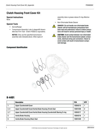
Clutch Housing Front Cover Kit AppendixTRSM0950Clutch Housing Front Cover KitSpecial Instructionsassembly lube or grease reduce O-ring effectiveness.None Special Tools ServiceRanger Transmission Assembly Lube (Lubegard Assemblee Goo Firm Tack - Green #19250 or equivalent)NOTICE: Only use the specified transmissionassembly lube indicated above. Other types ofNon-Chlorinated Brake Cleaner!DANGER: Do not handle non-chlorinated brakecleaner until all manufacturer precautions havebeen read and understood. Failure to follow precautions will result in serious personal injury or death.!CAUTION: Avoid contact between non-chlorinatedbrake cleaner and the transmission plastic components, electrical wiring and connectors. Failure toavoid contact will result in transmission component damage.Component r Countershaft Cover1000421512, 4Upper Countershaft Cover/Inertia Brake Housing (Front) Seal1000104823, 7Upper Countershaft Cover/Inertia Brake Housing Countershaft Bearing O-ring1000421725Inertia Brake Housing1000421616Inertia Brake Housing (Rear) Seal100010491 2019 Eaton Cummins Automated Transmission Technologies. All rights reserved2020.05.6
TRSM0950Appendix K-4491Manually Vent Linear Clutch Actuator (LCA)Drain Oil1. Key off.1. Locate the Oil Drain Plug on the back of the rear housing.2. Set vehicle parking brake and chock wheels.!WARNING: Apply vehicle parking brake and followvehicle manufacture parking instructions. Failure to follow these instructions could cause unintended vehiclemovement and may result in major vehicle componentdamage, severe injury of death.2. Place a suitable container under the Oil Drain Plug.Note: If reusing oil, use a clean container free of contamination and debris.3. Remove the Oil Drain Plug with a 6 mm hex key anddrain the oil.3. Loosen the 4 Linear Clutch Actuator (LCA) cap screws1-2 turns each with a T45 Torx.Note: Residual air pressure in the LCA cylinderexhausts between the LCA and Mechatronic Transmission Module (MTM) housing when the cap screws areloosened.4. Inspect Oil Drain Plug and O-ring for damage. If damaged, replace the Oil Drain Plug; O-ring is serviced withplug.5. Install the Oil Drain Plug (6 mm) and torque to24.5-29.5 Nm (18-22 lb-ft).4. Tighten the 4 LCA to MTM T45 cap screws and torqueto 23-27 Nm (17-21 lb-ft).2020.05.6NOTICE: Do not over-torque drain plug or transmissiondamage may occur. 2019 Eaton Cummins Automated Transmission Technologies. All rights reserved2
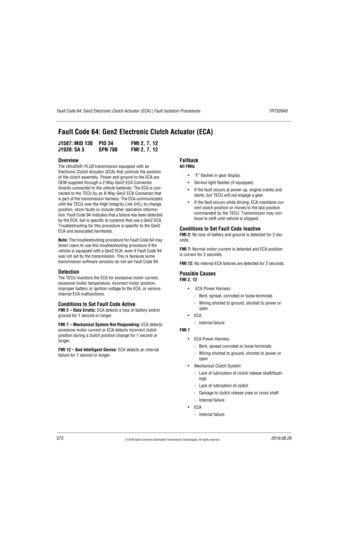
K-4491 AppendixTRSM0950Remove Transmission2. Pull to free the lower Clutch Release Yoke socket fromthe lower pivot on the clutch housing.1. Disconnect negative battery cable.2. Refer to OEM guidelines for transmission removal.Remove Release Bearing and Clutch ReleaseYoke1. Remove the Release Bearing by sliding the bearing offthe Input Shaft Cover.3. Pull to free the upper Clutch Release Yoke socket fromthe Linear Clutch Actuator (LCA) rod end.3 2019 Eaton Cummins Automated Transmission Technologies. All rights reserved2020.05.6
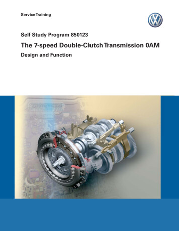
TRSM0950Appendix K-4491Remove Upper Countershaft Cover1. Remove the 6 Upper Countershaft Cover 13 mm capscrews and remove cover. The original cover is not tobe reused.2. Install the Upper Countershaft Cover CountershaftBearing O-ring (10004217) onto the Upper Countershaft Bearing.Note: O-ring may fall out of position after installation.Ensure to clean any residual oil from the bearing androll the O-ring on to the bearing using the tips of yourfingers pushing on the inner diameter of the O-ring. Ifnecessary, apply a small amount of transmissionassembly lube at the 3, 6, 9 and 12 o'clock positions tothe outer diameter of the bearing.Install Upper Countershaft Cover CountershaftBearing O-ring1. Clean any residual oil from the Upper CountershaftBearing outer diameter using Non-Chlorinated BrakeCleaner.2020.05.6 2019 Eaton Cummins Automated Transmission Technologies. All rights reserved4
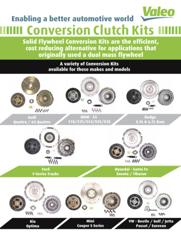
K-4491 AppendixTRSM0950Install Upper Countershaft Cover1. Clean the sealing surfaces on the clutch housing andthe new Upper Countershaft Cover.3. Install the new Upper Countershaft Cover and six 13mm cap screws to the clutch housing and torque to21-25 Nm (16-19 lb-ft) in a criss-cross pattern.Note: The new Upper Countershaft Cover has a chamfer that is required for the bearing O-ring.Remove Lower Countershaft Cover and InertiaBrake2. Install the new Upper Countershaft Cover O-ring(10001048) into the groove until fully seated.51. Depress and hold collar on air line fitting and disconnect the air line from the Inertia Brake Cover. 2019 Eaton Cummins Automated Transmission Technologies. All rights reserved2020.05.6
TRSM0950Appendix K-44912. Remove the 6 Inertia Brake Cover 13 mm cap screws.Disassemble Inertia Brake1. Remove the clutch pack from the Inertia Brake Housing.3. Remove the Inertia Brake Cover and Housing as anassembly. The original housing is not to be reused.2. Remove the 2 wear guides from the Inertia BrakeHousing.4. Ensure the Inertia Brake Piston Pin and Return Springremain in the Lower Countershaft.2020.05.6 2019 Eaton Cummins Automated Transmission Technologies. All rights reserved6
K-4491 AppendixTRSM0950Assemble Inertia Brake2. Insert the O-ring into the groove on the rear of the Inertia Brake Housing until fully seated.1. Clean sealing surfaces on the clutch housing and thenew Inertia Brake Housing.Note: The new Inertia Brake Housing has a chamfer onthe Clutch Housing side that is required for the bearingo-ring.3. Insert the O-ring into the groove on the front of theInertia Brake Housing until fully seated.7 2019 Eaton Cummins Automated Transmission Technologies. All rights reserved2020.05.6
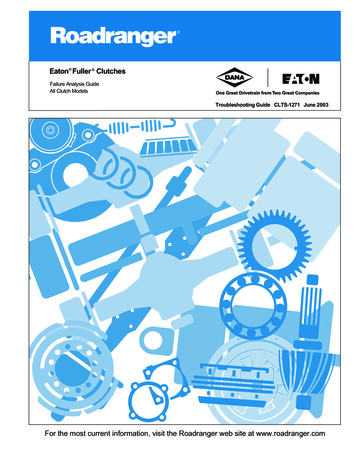
TRSM0950Appendix K-44914. Install the 2 Wear Guides in the Inertia Brake Housing.5. Install the inertia brake clutch pack in the order shownbelow: 1 Steel Disc, 1 Friction Disc, 2 Steel Discs, 1 Friction Disc, 2 Steel Discs, 1 Friction Disc, and 1 Steel Disc.Note: Steel Discs align with Wear Guides. FrictionDiscs spline to the lower countershaft.6. Place Inertia Brake Cover and Piston on the Housing.Align the bolt holes.2020.05.6 2019 Eaton Cummins Automated Transmission Technologies. All rights reserved8
K-4491 AppendixTRSM0950Install Inertia Brake Housing Countershaft Bearing O-ring1. Clean any residual oil from the Lower CountershaftBearing outer diameter using Non-Chlorinated BrakeCleaner.Install Inertia Brake Cover and Housing1. Install the Inertia Brake Cover and the new Housing asan assembly over the Lower Countershaft, rotate theassembly to align the Friction Discs to the LowerCountershaft splines and seat the assembly to theclutch housing.2. Install the Inertia Brake Housing Countershaft BearingO-ring (10004217) onto the Lower Countershaft Bearing.Note: O-ring may fall out of position after installation.Ensure to clean any residual oil from the bearing androll the O-ring on to the bearing using the tips of yourfingers pushing on the inner diameter of the O-ring. Ifnecessary, apply a small amount of transmissionassembly lube at the 3, 6, 9 and 12 o'clock positions tothe outer diameter of the bearing.2. While holding the Inertia Brake Housing to the clutchhousing, remove the Inertia Brake Cover.NOTICE: Ensure the Friction Discs are splined to thelower countershaft and Wear Guides are fully seated.9 2019 Eaton Cummins Automated Transmission Technologies. All rights reserved2020.05.6
TRSM0950Appendix K-44913. If removed, install the Return Spring into the LowerCountershaft.6. Install the six 13 mm cap screws and torque to 21-25Nm (16-19 lb-ft) in a criss-cross pattern.4. If removed, install the Piston Pin into the LowerCountershaft.7. Insert air line in push-to-connect fitting on the InertiaBrake Cover.5. Install the Inertia Brake Cover onto the housing.2020.05.6 2019 Eaton Cummins Automated Transmission Technologies. All rights reserved10
K-4491 AppendixTRSM0950Install Release Bearing and Clutch ReleaseYoke3. Slide the Release Bearing over the input shaft and intothe Release Yoke.1. Install the upper Release Yoke socket over the rod endof the Linear Clutch Actuator (LCA) and press untilattached.4. Push the upper end of the Release Yoke back until itlocks to reset the LCA.2. Install the lower Release Yoke socket over the lowerpivot on the clutch housing and press until attached.Install Transmission1. Refer to OEM guidelines for transmission installation.11 2019 Eaton Cummins Automated Transmission Technologies. All rights reserved2020.05.6
TRSM0950Appendix K-4491Fill Oil3. Fill the transmission with PS-386 lube until a smallamount of oil runs out of the Oil Check Plug hole.1. Remove the Oil Fill Plug with a 6 mm hex key.Note: Fill capacity is approximately 7.5-8.5 liters(16-18 pints) depending on the transmission angle.2. Place a suitable container under the Oil Check Plug andremove the Oil Check Plug with a 6 mm hex key.4. Inspect Oil Check Plug and O-ring for damage. If damaged, replace the Oil Check Plug; O-ring is servicedwith plug.2020.05.6 2019 Eaton Cummins Automated Transmission Technologies. All rights reserved12
K-4491 AppendixTRSM09505. Install the Oil Check Plug (6 mm) and torque to24.5-29.5 Nm (18-22 lb-ft).NOTICE: Do not over-torque the Oil Fill Plug or transmission damage may occur.5. Select “Start” Clutch Calibration and follow on-screenprompts.6. Key off and wait 1 minute.7. After waiting 1 minute, key on with engine off.8. Connect ServiceRanger.9. Go To “Fault Codes”. If an Active fault code sets, refer to Endurant Troubleshooting Guide TRTS0950. If NO Active fault codes set, select “Clear EatonFaults” and follow on-screen prompts.10. Disconnect ServiceRanger.11. Key off.6. Inspect Oil Fill Plug and O-ring for damage. If damaged, replace the Oil Fill Plug; O-ring is serviced withplug.7. Install the Oil Fill Plug (6 mm) and torque to 24.5-29.5Nm (18-22 lb-ft).NOTICE: Do not over-torque the Oil Fill Plug or transmission damage may occur.NOTICE: If PTO-equipped, start the engine and run for1 to 2 minutes to fill the PTO with oil, key off andrepeat the Oil Fill Procedure.8. Connect negative battery cable.Perform Transmission Service Routines1. Key on with engine running.2. Allow air pressure to build to governor cut-off.3. Connect ServiceRanger.4. Go To “Service Routines”.13 2019 Eaton Cummins Automated Transmission Technologies. All rights reserved2020.05.6
Remove Release Bearing and Clutch Release Yoke. 1. Remove the Release Bearing by sliding the bearing off the Input Shaft Cover. 2. Pull to free the lower Clutch Release Yoke socket from the lower pivot on the clutch housing. 3. Pull to free the upper Clut ch Release Yoke socket from the Linear Clutch Actuator (LCA) rod end.