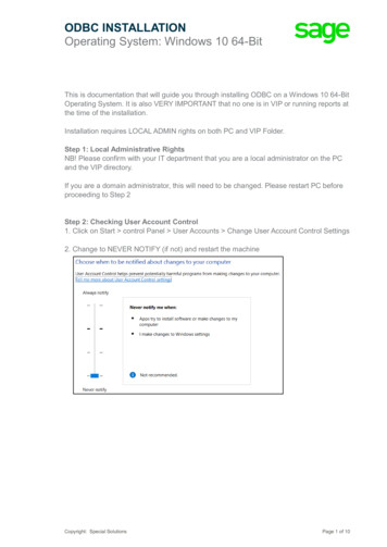
Transcription
ODBC Client Driver 2021 PTC Inc. All Rights Reserved.
ODBC Client Driver2Table of ContentsODBC Client Driver1Table of Contents2ODBC Client Driver4Overview4External Dependencies4Setup5Channel Properties — General5Tag Counts6Channel Properties — Write Optimizations6Channel Properties — Advanced7Channel Properties — Data Source Settings8Data Source Authentication9Device Properties — General9Operating Mode10Tag Counts11Device Properties — Scan Mode11Device Properties — Tag Generation12Device Properties — Data Source Access Method14Fixed Table14Table Selection15Auto Tag Database Generation Options15Timing Options16Dynamic Tables17Table Selection17Auto Tag Database Generation Options18Timing Options18Query18Building a Valid Query Statement19Miscellaneous Query Trigger Definition20Timing Options20Auto Tag Database Generation Options21Using the Query Access Method21Data Source Query Format22Modifying a Query Statement22Stored Procedure23Creating the Tag Database25www. ptc.com
ODBC Clien t Driver3Selecting a Different Stored ProcedureChoosing Query or Stored Procedure Access for Stored Procedure ExecutionRunning as a System Service262727Data Types Description28Address Descriptions29Error Descriptions30Address Validation30Missing address.30Device address address contains a syntax error.30Data Type type is not valid for device address address .30Device address address is read only.31Device Status Messages31Write request rejected on read only item reference channel name device name address .ODBC Client Driver Specific Messages3131Call to execute stored procedure stored procedure name on device device name failed.(Reason: ODBC Specific Error).32Data source data source name is configured as Read Only (all writes will be rejected).33Query validation failed due to the following: (Reason: ODBC Specific Error).33Unable to retrieve table names. (Reason: ODBC Specific Error).33Unable to retrieve table column names. (Reason: ODBC Specific Error).34Unable to retrieve table row count. (Reason: ODBC Specific Error).34Unable to retrieve stored procedure names. (Reason: ODBC Specific Error).35Unable to retrieve supported access methods. (Reason: ODBC Specific Error).35Unable to connect to data source on channel channel name . (Reason: ODBC Specific Error).35Unable to open recordset on device device name . (Reason: ODBC Specific Error).36Unable to query recordset on device device name . (Reason: ODBC Specific Error).36Unable to retrieve database value for tag tag address on device device name .37Unable to write database value value for tag tag address on device device name .37Unable to read internal tag tag address on device device name (Reason: ODBC SpecificError).38Unable to write to internal tag tag address on device device name (Reason: ODBC SpecificError).38Unable to read parameter tag tag address . (Reason: ODBC Specific Error).38Unable to write to parameter tag tag address (Reason: ODBC Specific Error).39Unable to execute stored procedure stored procedure name on device device name .(Reason: ODBC Specific Error).39Unable to write to item tag address (Reason: ODBC Specific Error).39Index41www. ptc.com
ODBC Client Driver4ODBC Client DriverHelp version 1.057CONTENTSOverviewWhat is the ODBC Client Driver?Set upHow do I configure the ODBC Client Driver to communicate with ODBC data sources?Dat a Types Descript ionWhat data types are supported by this driver?Address Descript ionsHow do I address a data location in my ODBC data source?Error Descript ionsWhat error messages are produced by the ODBC Client Driver?OverviewThe ODBC Client Driver provides a reliable way to connect ODBC data sources to OPC Client applications,including HMI, SCADA, Historian, MES, ERP, and countless custom applications. It provides single-pointaccess to multiple ODBC data sources via ODBC. Through the power and speed of OPC, the server can offerODBC data to any OPC/DDE enabled client.ODBC Client Driver FeatureslMultiple connection sessions to multiple ODBC data sourceslRead/Write to the SQL enginelAutomatic tag generation based on tables, queries, and stored procedures from the ODBC datasourcelOPC DAlDrag and drop editinglCSV import and export for easy manipulation of tagslData ScalinglSystem Tags for general error feedback to client applicationslTags that can be added to the application at any time (even at Runtime)lThe ability to run as a System ServicelA built-in User Manager for complete control over individual user functionality and privilegesExt ernal DependenciesThis driver has external dependencies. It requires Microsoft Data Access Components (MDAC), which consist of several core components that provide various database technologies (including ODBC and itsdrivers).www. ptc.com
ODBC Clien t Driver5Set upSupported ODBC Data SourcesODBC-compliant data sources are supported. Examples include:lMicrosoft AccesslMicrosoft SQLlMySQL*lOracle* If the project uses a MySQL data source, users must select MySQL from the Model drop-down list when creating a device. This makes the driver accommodate MySQL's data handling requirements. The PC that is running the OPC server must have the MyODBC driver installed, as well.RecordsetsThe MySQL model uses Snapshot-type recordsets; all other ODBC data sources use Dynaset.Communication ProtocolODBC APIChannel and Device LimitsThe maximum number of channels supported by this driver is 256. The maximum number of devices supported by this driver is 4096 per channel.N ote: In this driver, the channel corresponds to the ODBC Driver and its particular ODBC data source.Channel Propert ies — GeneralThis server supports the use of multiple simultaneous communications drivers. Each protocol or driver usedin a server project is called a channel. A server project may consist of many channels with the same communications driver or with unique communications drivers. A channel acts as the basic building block of anOPC link. This group is used to specify general channel properties, such as the identification attributes andoperating mode.IdentificationN am e: Specify the user-defined identity of this channel. In each server project, each channel name must beunique. Although names can be up to 256 characters, some client applications have a limited display windowwhen browsing the OPC server's tag space. The channel name is part of the OPC browser information. Theproperty is required for creating a channel.For information on reserved characters, refer to "How To. Properly Name a Channel, Device, Tag, and TagGroup" in the server help.www. ptc.com
ODBC Client Driver6Description: Specify user-defined information about this channel.Many of these properties, including Description, have an associated system tag.Driver: Specify the protocol / driver for this channel. This property specifies the device driver that was selected during channel creation. It is a disabled setting in the channel properties. The property is required for creating a channel.N ote: With the server's online full-time operation, these properties can be changed at any time. Thisincludes changing the channel name to prevent clients from registering data with the server. If a client hasalready acquired an item from the server before the channel name is changed, the items are unaffected. If,after the channel name has been changed, the client application releases the item and attempts to reacquire using the old channel name, the item is not accepted. Changes to the properties should not be madeonce a large client application has been developed. Utilize proper user role and privilege management toprevent operators from changing properties or accessing server features.DiagnosticsDiagnostics Capture: When enabled, this option makes the channel's diagnostic information available toOPC applications allows the usage of statistics tags that provide feedback to client applications regardingthe operation of the channel. Because the server's diagnostic features require a minimal amount of overhead processing, it is recommended that they be utilized when needed and disabled when not. The default isdisabled.N ote: This property is not available if the driver does not support diagnostics.For more information, refer to "Communication Diagnostics" and "Statistics Tags" in the server help.Tag CountsStatic Tags: Provides the total number of defined static tags at this level (device or channel). This information can be helpful in troubleshooting and load balancing.Channel Propert ies — Writ e Opt im izat ionsThe server must ensure that the data written from the client application gets to the device on time. Giventhis goal, the server provides optimization properties to meet specific needs or improve application responsiveness.Write OptimizationsOptim ization Method: Controls how write data is passed to the underlying communications driver. Theoptions are:lWrite All Values for All Tags: This option forces the server to attempt to write every value to thecontroller. In this mode, the server continues to gather write requests and add them to the server'sinternal write queue. The server processes the write queue and attempts to empty it by writing datato the device as quickly as possible. This mode ensures that everything written from the client applications is sent to the target device. This mode should be selected if the write operation order or thewww. ptc.com
ODBC Clien t Driver7write item's content must uniquely be seen at the target device.llWrite Only Latest Value for N on-Boolean Tags: Many consecutive writes to the same value canaccumulate in the write queue due to the time required to actually send the data to the device. If theserver updates a write value that has already been placed in the write queue, far fewer writes areneeded to reach the same final output value. In this way, no extra writes accumulate in the server'squeue. When the user stops moving the slide switch, the value in the device is at the correct value atvirtually the same time. As the mode states, any value that is not a Boolean value is updated in theserver's internal write queue and sent to the device at the next possible opportunity. This can greatlyimprove the application performance.N ote: This option does not attempt to optimize writes to Boolean values. It allows users to optimizethe operation of HMI data without causing problems with Boolean operations, such as a momentarypush button.Write Only Latest Value for All Tags: This option takes the theory behind the second optimizationmode and applies it to all tags. It is especially useful if the application only needs to send the latestvalue to the device. This mode optimizes all writes by updating the tags currently in the write queuebefore they are sent. This is the default mode.Duty Cycle: is used to control the ratio of write to read operations. The ratio is always based on one read forevery one to ten writes. The duty cycle is set to ten by default, meaning that ten writes occur for each readoperation. Although the application is performing a large number of continuous writes, it must be ensuredthat read data is still given time to process. A setting of one results in one read operation for every writeoperation. If there are no write operations to perform, reads are processed continuously. This allows optimization for applications with continuous writes versus a more balanced back and forth data flow.N ote: It is recommended that the application be characterized for compatibility with the write optimizationenhancements before being used in a production environment.Channel Propert ies — AdvancedThis group is used to specify advanced channel properties. Not all drivers support all properties; so theAdvanced group does not appear for those devices.N on-N orm alized Float Handling: A non-normalized value is defined as Infinity, Not-a-Number (NaN), or asa Denormalized Number. The default is Replace with Zero. Drivers that have native float handling maydefault to Unmodified. Non-normalized float handling allows users to specify how a driver handles non-normalized IEEE-754 floating point data. Descriptions of the options are as follows:llReplace with Zero: This option allows a driver to replace non-normalized IEEE-754 floating point values with zero before being transferred to clients.Unm odified: This option allows a driver to transfer IEEE-754 denormalized, normalized, non-number, and infinity values to clients without any conversion or changes.N ote: This property is disabled if the driver does not support floating-point values or if it only supports theoption that is displayed. According to the channel's float normalization setting, only real-time driver tags(such as values and arrays) are subject to float normalization. For example, EFM data is not affected by thissetting.www. ptc.com
ODBC Client Driver8For more information on the floating-point values, refer to "How To . Work with Non-Normalized FloatingPoint Values" in the server help.Inter-Device Delay: Specify the amount of time the communications channel waits to send new requests tothe next device after data is received from the current device on the same channel. Zero (0) disables thedelay.N ote: This property is not available for all drivers, models, and dependent settings.Channel Propert ies — Dat a Source Set t ingsThe Data Source Settings group is used to select a data source and configure connection specific properties.Data Source: This property specifies the Data Source Name (DSN). Click on the browse button to launch theData Source Selection dialog. Select a DSN from the menu. The DSN must be created and configured for thedata source before it will appear in the menu. Click on the Configure DSN button to launch theMicrosoft ODBC Data Source Adm inistrator.Usernam e: This property specifies the user name. It is only needed if required by the data source (such as inSQL server authentication).Password: This property specifies the password. It is only needed if required by the data source (such as inSQL server authentication).Login Tim eout (s): This property specifies the number of seconds that the server will wait for a responsebefore timing out when attempting to connect to the ODBC data source. The valid range is 1 to 99999seconds. The default setting is 5 seconds.N ote: Some data sources can use Windows Authentication to gain access to the data source. If the datasource is configured to use Windows Authentication, it will ignore the User Name and Password and will usethe Network Login ID instead.Configuring a DSNThe example below uses System DSNs, which are local to the computer but not user-dedicated. This meansthat they can be accessed by any user with privileges. User DSNs, which are also local to the computer, areonly accessible by the current user.Caution: System DSNs must be used when the OPC server is configured to run as a System Service; otherwise, tags will neither be automatically generated nor be Good quality in projects in which they are alreadycontained.1. To start, click Configure DSN to invoke the Microsoft ODBC Data Source Adm inistrator.2. Then, map an ODBC data source to a data source name.N ote: Once a DSN has been created successfully, it will appear in the Data Source drop-down menu.www. ptc.com
ODBC Clien t Driver9Device Access M et hodPropert ies Requiring Updat e When DSN ChangesFixed TableTable SelectionLimit Import ColumnsMaximum Records to ImportDynamic TableTable SelectionQueryQueryTrigger ColumnStored ProcedureStored Procedure SelectionDat a Source Aut hent icat ionWindow s AuthenticationSome data sources may be configured to use authentication for security. The SQL Server can authenticatewith Windows by default using the Network Login ID. This makes the SQL server login transparent, and eliminates the need for a user name and password in the channel's Data Source Settings property group.SQL Server AuthenticationThe SQL server also has its own authentication method. To connect the OPC server to the SQL server usingSQL authentication, users must set the authentication method in the SQL server to allow SQL authentication.Users must also specify the Login ID and Password. After these properties are defined, the user name andpassword may then be entered in the OPC server in the channel's Data Source Settings tab. FSee Also: Running as a System ServiceDevice Propert ies — GeneralA device represents a single target on a communications channel. If the driver supports multiple controllers,users must enter a device ID for each controller.IdentificationN am e: Specify the name of the device. It is a logical user-defined name that can be up to 256 characterslong and may be used on multiple channels.www. ptc.com
ODBC Client Driver10N ote: Although descriptive names are generally a good idea, some OPC client applications may have alimited display window when browsing the OPC server's tag space. The device name and channel namebecome part of the browse tree information as well. Within an OPC client, the combination of channel nameand device name would appear as "ChannelName.DeviceName".For more information, refer to "How To. Properly Name a Channel, Device, Tag, and Tag Group" in serverhelp.Description: Specify the user-defined information about this device.Many of these properties, including Description, have an associated system tag.Channel Assignm ent: Specify the user-defined name of the channel to which this device currently belongs.Driver: Selected protocol driver for this device.Model: Specify the type of device that is associated with this ID. The contents of the drop-down menudepend on the type of communications driver being used. Models that are not supported by a driver are disabled. If the communications driver supports multiple device models, the model selection can only bechanged when there are no client applications connected to the device.N ote: If the communication driver supports multiple models, users should try to match the model selection to the physical device. If the device is not represented in the drop-down menu, select a model that conforms closest to the target device. Some drivers support a model selection called "Open," which allows usersto communicate without knowing the specific details of the target device. For more information, refer to thedriver help documentation.ID: Specify the device's driver-specific station or node. The type of ID entered depends on the communications driver being used. For many communication drivers, the ID is a numeric value. Drivers that support a Numeric ID provide users with the option to enter a numeric value whose format can be changed tosuit the needs of the application or the characteristics of the selected communications driver. The format isset by the driver by default. Options include Decimal, Octal, and Hexadecimal.N ote: If the driver is Ethernet-based or supports an unconventional station or node name, the device'sTCP/IP address may be used as the device ID. TCP/IP addresses consist of four values that are separated byperiods, with each value in the range of 0 to 255. Some device IDs are string based. There may be additionalproperties to configure within the ID field, depending on the driver. For more information, refer to the driver'shelp documentation.Operating M odeData Collection: This property controls the device's active state. Although device communications areenabled by default, this property can be used to disable a physical device. Communications are not attempted when a device is disabled. From a client standpoint, the data is marked as invalid and write operationsare not accepted. This property can be changed at any time through this property or the device system tags.Sim ulated: Place the device into or out of Simulation Mode. In this mode, the driver does not attempt tocommunicate with the physical device, but the server continues to return valid OPC data. Simulated stopsphysical communications with the device, but allows OPC data to be returned to the OPC client as valid data.www. ptc.com
ODBC Clien t Driver11While in Simulation Mode, the server treats all device data as reflective: whatever is written to the simulateddevice is read back and each OPC item is treated individually. The item's memory map is based on the groupUpdate Rate. The data is not saved if the server removes the item (such as when the server is reinitialized).The default is No.N otes:1. This System tag ( Simulated) is read only and cannot be written to for runtime protection. The Systemtag allows this property to be monitored from the client.2. In Simulation mode, the item's memory map is based on client update rate(s) (Group Update Rate forOPC clients or Scan Rate for native and DDE interfaces). This means that two clients that referencethe same item with different update rates return different data.Simulation Mode is for test and simulation purposes only. It should never be used in a production environment.Tag CountsStatic Tags: Provides the total number of defined static tags at this level (device or channel). This information can be helpful in troubleshooting and load balancing.Device Propert ies — Scan M odeThe Scan Mode specifies the subscribed-client requested scan rate for tags that require device communications. Synchronous and asynchronous device reads and writes are processed as soon as possible;unaffected by the Scan Mode properties.Scan Mode: Specify how tags in the device are scanned for updates sent to subscribing clients. Descriptionsof the options are:llllRespect Client-Specified Scan Rate: This mode uses the scan rate requested by the client.Request Data N o Faster than Scan Rate: This mode specifies the value set as the maximum scanrate. The valid range is 10 to 99999990 milliseconds. The default is 1000 milliseconds.N ote: When the server has an active client and items for the device and the scan rate value isincreased, the changes take effect immediately. When the scan rate value is decreased, the changesdo not take effect until all client applications have been disconnected.Request All Data at Scan Rate: This mode forces tags to be scanned at the specified rate for subscribed clients. The valid range is 10 to 99999990 milliseconds. The default is 1000 milliseconds.Do N ot Scan, Dem and Poll Only: This mode does not periodically poll tags that belong to thedevice nor perform a read to get an item's initial value once it becomes active. It is the OPC client'swww. ptc.com
ODBC Client Driver12responsibility to poll for updates, either by writing to the DemandPoll tag or by issuing explicit devicereads for individual items. For more information, refer to "Device Demand Poll" in server help.lRespect Tag-Specified Scan Rate: This mode forces static tags to be scanned at the rate specifiedin their static configuration tag properties. Dynamic tags are scanned at the client-specified scanrate.Initial Updates from Cache: When enabled, this option allows the server to provide the first updates fornewly activated tag references from stored (cached) data. Cache updates can only be provided when thenew item reference shares the same address, scan rate, data type, client access, and scaling properties. Adevice read is used for the initial update for the first client reference only. The default is disabled; any time aclient activates a tag reference the server attempts to read the initial value from the device.Device Propert ies — Tag Generat ionThe automatic tag database generation features make setting up an application a plug-and-play operation.Select communications drivers can be configured to automatically build a list of tags that correspond todevice-specific data. These automatically generated tags (which depend on the nature of the supportingdriver) can be browsed from the clients.Not all devices and drivers support full automatic tag database generation and not all support the same datatypes. Consult the data types descriptions or the supported data type lists for each driver for specifics.If the target device supports its own local tag database, the driver reads the device's tag information anduses the data to generate tags within the server. If the device does not natively support named tags, thedriver creates a list of tags based on driver-specific information. An example of these two conditions is as follows:1. If a data acquisition system supports its own local tag database, the communications driver uses thetag names found in the device to build the server's tags.2. If an Ethernet I/O system supports detection of its own available I/O module types, the communications driver automatically generates tags in the server that are based on the types of I/O modules plugged into the Ethernet I/O rack.N ote: Automatic tag database generation's mode of operation is completely configurable. For more information, refer to the property descriptions below.On Property Change: If the device supports automatic tag generation when certain properties change, theOn Property Change option is shown. It is set to Yes by default, but it can be set to N o to control over whentag generation is performed. In this case, the Create tags action must be manually invoked to perform taggeneration. To invoke via the Configuration API service, access services/TagGeneration.www. ptc.com
ODBC Clien t Driver13On Device Startup: Specify when OPC tags are automatically generated. Descriptions of the options are asfollows:lllDo N ot Generate on Startup: This option prevents the driver from adding any OPC tags to the tagspace of the server. This is the default setting.Always Generate on Startup: This option causes the driver to evaluate the device for tag information. It also adds tags to the tag space of the server every time the server is launched.Generate on First Startup: This option causes the driver to evaluate the target device for taginformation the first time the project is run. It also adds any OPC tags to the server tag space asneeded.N ote: When the option to automatically generate OPC tags is selected, any tags that are added to theserver's tag space must be saved with the project. Users can configure the project to automatically savefrom the Tools Options menu.On Duplicate Tag: When automatic tag database generation is enabled, the server needs to know what todo with the tags that it may have previously added or with tags that have been added or modified after thecommunications driver since their original creation. This setting controls how the server handles OPC tagsthat were automatically generated and currently exist in the project. It also prevents automatically generated tags from accumulating in the server.For example, if a user changes the I/O modules in the rack with the server configured to Always Generateon Startup, new tags would be added to the server every time the communications driver detected a newI/O module. If the old tags were not removed, many unused tags could accumulate in the server's tag space.The options are:llDelete on Create: This option deletes any tags that were previously added to the tag space beforeany new tags are added. This is the default setting.Overwrite as N ecessary: This option instructs the server to only remove the tags that the communications driver is replacing with new tags. Any tags that are not being overwritten remain in theserver's tag space.llDo not Overwrite: This option prevents the server from removing any tags that were previously generated or already existed in the server. The communications driver can only add tags that are completely new.Do not Overwrite, Log Error: This option has the same effect as the prior option, and also posts anerror message to the server's Event Log when a tag overwrite would have occurred.N ote: Removing OPC tags affects tags that have been automatically generated by the communications driver as well as any tags that have been added using names that match generated tags.Users should avoid adding tags to the server using names that may match tags that are automaticallygenerated by the driver.Parent Group: This property keeps automatically generated tags from mixing with tags that have beenentered manually by specifying a group to be used for automatically generated tags. The name of the groupcan be up to 256 characters. This parent group provides a root branch to which all automatically generatedtags are added.Allow Autom atically Generated Subgroups: This property controls whether the server automatically creates subgroups for the automatically generated tags. This is the default setting. If disabled, the server generates the device's tags in a flat list without any grouping. In the server project, the resulting tags are namedwith the address value. For example, the tag names are not retained during the generation process.www. ptc.com
ODBC Client Driver14N ote: If, as the server is generating tags, a tag is assigned the same name as an existing tag, the systemautomatically increments to the next highest number so that the tag name is not duplicated. For example, ifthe generation process creates a tag named "AI22" that already exists, it creates the tag as "AI23" instead.Create: Initiates the creation of automatically generated OPC tags. If the device's configuration has beenmodified, Create tags forces the driver to reevaluate the device for possible tag changes. Its ability to beaccessed from the System tags allows a client application to initiate tag database creation.N ote: Create tags is disabled if the Configuration edits a project offline.Device Propert ies — Dat a Source Access M et hodAccess M ethod SelectionOnce a channel with a defined ODBC data source is created, a device must be created for each accessmethod desired. Options include Fixed Table, Dynam ic Table, Query, and Stored Procedure. This canonly be selected during device creation.Fixed TableDynamic TableQuerySt ored ProcedureN otes:
ODBC Client Driver Setup SupportedODBCDataSources ude: l MicrosoftAccess l MicrosoftSQL l MySQL* l Oracle .

