Transcription
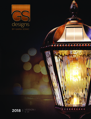
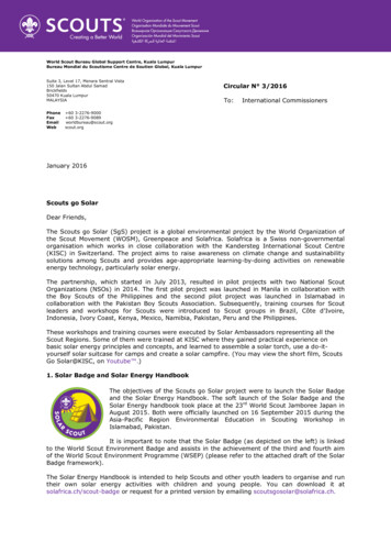
HARMONICS ISSUES THAT LIMIT SOLAR PHOTOVOLTAICGENERATION ON DISTRIBUTION CIRCUITSKetut DartawanPterra Consulting, LLC4 Automation Lane, Ste 250Albany, NY 12205 USAEmail: ketutdartawan@pterra.usLe HuiPterra Consulting, LLC4 Automation Lane, Ste 250Albany, NY 12205 USAEmail: lhui@pterra.usABSTRACTThis paper describes the authors’ analysis of harmonics issuesthat limit the amount of solar photovoltaic (PV) generation ina 12.47 kV distribution circuit with major capacitors installedat the substation. The capacitors introduce resonantfrequencies in the circuit which may be excited by harmoniccurrents from inverter based PV units on the same circuit. Thisleads to potential voltage or current distortions beyond thecriteria specified in the IEEE-519 or IEEE-1547 standards,thereby limiting the amount of PV penetration on the circuit.To allow more PV penetration, countermeasures such asinstalling harmonic filters and repurposing capacitors may beapplied. In addition, the authors identify appropriate ways tointerpret the standards, model the study circuit for simulationand develop assumptions for analysis. The paper concludeswith recommendations on best practices to model and identifyharmonic constraints in a distribution circuit with bothcapacitors and PV inverters, and on the application ofmitigation solutions that lead to more PV penetration withoutsacrificing the safety and reliability of the distribution system.Ricardo AustriaPterra Consulting, LLC4 Automation Lane, Ste 250Albany, NY 12205 USAEmail:ricaustria@pterra.usMark SuehiroMaui Electric Company, Ltd.P.O. Box 398Kahului, HI 96733 USAEmail: mark.suehiro@mauielectric.commotors, lines, and cables which can lead to shortened life,interference with communication systems (generally forservices on the same electric pole such as cable TV andphone) and with the operation of sensitive loads, and outagesassociated with blown fuses and failed equipment. Powerelectronic converters, which are widely used in modern powersystems, are some of the major sources of harmonics. Solarphotovoltaic generation depend extensively upon powerelectronic converters to produce alternating current output forinterconnection purposes. Therefore, the harmonic issue is onethe most important aspects affecting the integration ofrenewable energies.IEEE Standard 519-1992 [2] is the standard that specifieslimits on the amount of harmonics allowed in the grid. On theother hand, IEEE Standard 1547-2003 [3] focuses on theinterconnection requirements of renewable resources. Thesetwo standards inform the model development and simulationmethods used in this paper. A case study described in thispaper illustrates how PV penetration on a 12.47 kVdistribution circuit may be limited by harmonic issues.1. INTRODUCTION2. SIMULATION SETUPHarmonics of a waveform are components whose frequenciesare multiple integers of a 60 Hz or 50 Hz fundamental wave.For example, 120 Hz, 180 Hz, 240 Hz, and 300 Hz are the 2nd,3rd, 4th and 5th harmonic components of a 60 Hz fundamentalwaveform. Harmonic distortion is usually caused by nonlinear devices in electric power systems [1]. Harmonics pose arisk to power systems in terms of overheating of transformers,2.1 Modeling of the Study 12.47 kV circuitThe study in this paper is based on a 12.47 kV distributioncircuit supplied from a 10 MVA 69/12.47 kV substationtransformer as illustrated in Fig. 1. There are two feedersconnected to the 12.47 kV bus. One feeder is a 10-mileoverhead line with a 3 MVA lumped load at a power factor1
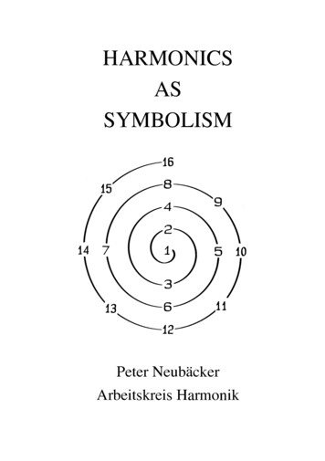
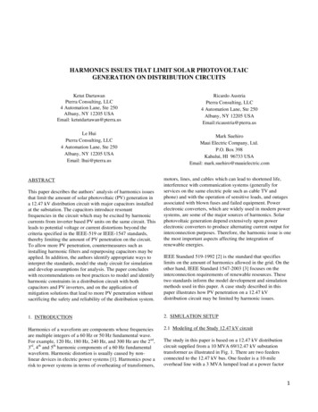
(p.f.) of 0.9 lagging under peak load connected at the end ofthe feeder. This represents a distribution feeder in a rural areawhere customer load may be served over a long distance. Theother feeder is composed of a 2-mile 500 MCM undergroundcable with a total load of 3 MVA (0.9 p.f.) lagging at peakload. The load is represented by 4 lumped equivalents atlocations Load#1 4. This feeder is connected to the 12.47 kVbus through utility transformers (Utility TSF#1 4). Four 3phase PV units rated at 500 kW each are also connected tothese utility transformers. Four additional 3-phase PV unit#1 4 are also connected along the 2-mile feeder to test PVpenetration limits. The minimum load is assumed to be 50% ofthe peak load. The utility short circuit contribution at peakload condition is 597.5 MVA for a 3-phase fault and 250MVA for a line-ground fault. The utility short circuitcontribution at minimum load is assumed to be 50% of thepeak load contribution.Capacitors are sometimes installed at a main substation forvoltage control of distribution circuits. In this study, there is a3-stage 4 Mvar capacitor bank connected at the 12.47 kV bus,as shown in Fig. 1, which can operate at 1, 2, or 4 Mvar.are major sources of harmonics. The harmonic current isinjected from the inverters to the distribution circuitpotentially affecting customers connected to the same circuit.The profile of harmonic content can vary significantly amongthe many commercially available UL listed PV inverters. Twoexamples, both taken from actual measurements, are shown inFig. 2. In the first example, identified as Type-1, the inverterproduces a total harmonic distortion (THD) of current slightlyless than 3% (ITHD 3%). For this PV inverter, the AC outputwaveform visually shows some distortion but remains close toa sine wave. In the second example, identified as Type-II, ITHDis higher than 5%. For this second PV inverter, the AC outputwaveform clearly shows more distortion of the sine wave. Foranalysis purposes, particularly where the harmonic spectrumof a specific PV unit is not available, the Type-II may be usedto represent a worst case model. In the study reported in thispaper, both Type-I and Type-II inverters are applied in theanalysis.Fig. 1: An Illustration of the Study 12.47 kV DistributionCircuit2.2 Harmonic SourcesA PV unit is comprised of the PV panels that generate DC,and the inverter, which converts DC to AC, as illustrated inFig. 1 (PV unit#1). Inverters are power electronic devices thatFig. 2: Type-I and Type-II Current Harmonics of PV Units(Type-II adapted from [4])2
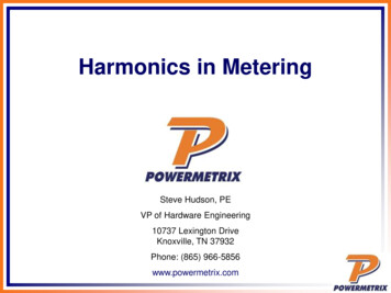
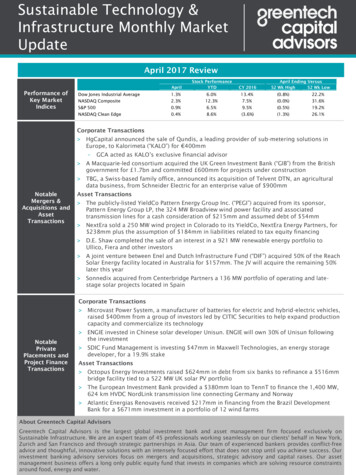
In addition, there is also a certain amount of backgroundharmonics in the distribution circuit coming from customer loadand utility equipment. For purposes of analysis, the backgroundharmonic current is assumed to be 2% of the total load currenton the 2-mile long feeder, with the contribution from TV andcomputers, fluorescent lamps and compact fluorescent evenlydivided. The typical harmonic content of different types ofconsumer devices is listed in Table 1.TABLE 1: TYPICAL HARMONIC CONTENT OFRESIDENTIAL AND COMMERCIAL LOADSHarmonic Sources 40.10Case 1 and Case 2 apply to overnight hours from 9 pm to 8 amcharacterized by light loading. During this period, thecapacitors are out of service and the output of PV units is zeroor very low. Therefore, harmonic issues are not likely to be aconcern for these cases and Case 1 and Case 2 are not studied.Case 3 and Case 4, on the other hand, represent the situationwhen the capacitor banks are likely to be in use andintroducing resonant frequencies on the circuit. The staging ofthe capacitor banks are such that there are three potentialconfigurations for capacitor size: 1, 2 and 4 Mvar.Furthermore, during the time range of Case 3 and Case 4, solarinsolation can result in any number of PV units being online.For purposes of analysis, the maximum amount of PVconsidered for the study circuit is 2 MW, which is the totaloutput of the four PV units of 500 kW each, with the potentialto add four more additional 750 kW PV units. The PVinverters’ harmonics in combination with backgroundharmonics could excite the resonant frequency or frequenciesof the circuit with capacitor banks in service leading toharmonic content that violates standards. To compare impactsat the point of common coupling (PCC), the analysis furthertests inverters as being either Type-I or Type-II.3.2 Criteria3. STUDY APPROACH3.1 Study CasesConsidering the circuit load, operation of the capacitor bank aswell as the output of PV units, there are mainly 4 differentcases as summarized in Fig. 3 and Table 2.Fig. 3: System Loading Time ProfileTABLE 2: SIMULATION CASES TO DETERMINEHARMONIC IMPACT ON DISTRIBUTION CIRCUITCaseLoadingCase 1Case 2Case 3Case tedoffononoffNoNoYesYesTable 3 shows the limit for voltage THD and the individualvoltage harmonics specified in IEEE Standard 519-1992 forelectrical circuits rated 2.3 kV and higher. For the 12.47 kVbus of the study circuit, the voltage THD is limited to 5% andindividual harmonic content should not exceed 3%. IEEEStd-1547 states that before a distributed resource is added tothe system, the voltage distortion on the system should belower than 2.5%. However, IEEE Std-1547 does not providethe voltage distortion limit after the distributed resource isadded to the system. Thus, the study reported in this paperuses the IEEE Std-519 limits (given in Table 10.3 of thestandard) to determine the allowable PV penetration level.Table 4 lists the maximum harmonic current distortion inpercentage as specified in IEEE Std-519 in the voltage rangeof 0.12 - 69 kV. IEEE Std-1547 adopts the A1 criteria in IEEEStd-519 (ISC/IL 20, ITHD 5%) as in Table 4, which is morerestrictive than IEEE Std-519 when ISC/IL is larger. Theauthors note that IEEE Std-519 has a very strict limit on evenharmonics, which is 25% of the preceding odd harmonic.When IEEE Std-519 was first introduced, most of theharmonic sources were 3-phase drives and other largeequipment that had little even harmonics. Ostensibly, a valuefor the even harmonics of 25% of the odd harmonics wasarbitrarily assigned since it was not then a controlling factor.As seen by the harmonic content of the PV inverters in Fig. 2,there are even harmonics whose magnitudes are comparable tothe odd harmonics. Technically there is no reason why the oldharmonics are more detrimental to the system than the even3
harmonics. It is the authors’ opinion that the even harmonicsshould have the same criteria as the odd harmonics. Therefore,for the study system, modified criteria are applied, where themaximum harmonic distortions of the even harmonics are thesame as the preceding odd harmonics. Furthermore, this paperuses a modified IEEE Std-1547 as well as the modified IEEEStd-519to find the maximum PV penetration.TABLE 3: HARMONIC VOLTAGE DISTORTION LIMITSFOR NON-LINEAR LOADS AT THE POINT OF COMMONCOUPLING (PCC) (ADAPTED FROM IEEE-519 1992)Harmonic Voltage Distortion in % at PCC2.3 - 6969 - 161 161kVkVkVMaximum for3.01.51.0Individual HarmonicTotal Harmonic5.02.51.5Distortion (THD)TABLE 4: MAXIMUM HARMONIC CURRENTDISTORTION IN % OF LOAD DEMAND CURRENT(ADAPTED FROM IEEE STD 519 1992 TABLE 10.3)Maximum Harmonic Current Distortion in % of LoadDemand CurrentVoltages 0.12-69-kVIDbased on Table 10.3 IEEE Std 519 1992Harmonic Order (Odd Harmonics)ISC/ILTHD 11 11 h 17 17 h 23 23 h 35 35 hA1 20*421.50.60.35A220 5073.52.510.58A3 50 100 104.541.50.712A4 100 1000 125.552115A5 1000 15762.51.420Even harmonics are limited to 25% of the odd harmonic limitsabove.* All power generation equipment is limited to these values ofCurrent distortion, regardless of actual ISC/IL.where: ISC Maximum short-circuit current at PCCand IL Maximum load demand current (fundamental frequency)at PCC4. ANALYSIS, RESULTS AND DISCUSSIONSThe following are the steps taken in conducting the analysis ofharmonic impacts. First, the impedance scan is performed atthe PCC as well as at the 12.47 kV bus, assuming differentoperating conditions to find the resonance points. Second,Type-I and Type-II harmonics are injected from each PV unitto evaluate the voltage and current THD. The results arecompares to the limits specified in IEEE Std-519. The criticalpenetration level is identified at the PCC and at the 12.47 kVbus.4.1 Capacitors and Resonance PointsIt is essential to know the operating mode of the capacitorbank. The capacitor bank introduces parallel resonance due tointeraction between the capacitive reactance and circuitinductive reactance. If the parallel resonance occurs at afrequency near a major PV harmonic current contribution, theharmonic current is excited and amplified and can lead to largeoscillating currents, and, consequently, high harmonicvoltages. The impedance scans in Fig. 4 show that theresonant frequency for the case without the capacitor occursaround the 35th harmonic order, where the harmoniccontribution from PV units is negligible. The backgroundharmonics whose major components are no higher than the17th order harmonics, as shown in Table 1, do not introduce aharmonic issue either. With the capacitor bank in service,however, the resonant frequencies are shifted to a much lowerfrequency between the 5th and the 10th harmonic orders. Boththe background harmonic and the harmonic contribution fromthe PV units have a considerable amount of contributionaround the 5th order, and therefore could lead to seriousvoltage or current distortions. The worst case occurs duringnoon time when there is heavy loading, the capacitor bank isin service at the maximum of 4 Mvar and PV units producetheir maximum output, as in Case 3 in Table 2 and Fig. 3.3.3 Point of Common CouplingIn the circuit model, as there are loads connected to thesecondary side of the utility transformers, where the PV unitsare also connected, the point of common coupling (PCC) arethe 480 V buses, as illustrated in Fig. 1.It is possible that thecumulative effects of a number of harmonic sources can resultin violation of the harmonic limits on the utility side, evenwhen the harmonic distortion from each individual PV unit iswithin criteria [5]. The 12.47 kV bus, therefore, is alsomonitored to determine if there is harmonic impact on thedistribution circuit.Fig. 4: Impedance Scan at the 12.47 kV Bus4
To provide a baseline for determining maximum penetrationlevels, the first simulation case assumes that the capacitorbank is operated at 4 Mvar and the PV units introduce Type-Iharmonics. Background harmonics are not included in thiscase. Fig. 5 and Fig. 6 show, respectively, the voltagedistortion percentage at the 12.47 kV bus and the currentdistortion percentage at the secondary side of the utilitytransformer where PV units are connected. Fig. 5 indicatesthat up to 5 MW of PV has no violation of the IEEE Std-519on individual voltage distortion (3%) and the VTHD (5%). Fig.6 shows also that no violation of the current harmonics criteriafor penetration levels of up to 5 MW occurs for the Type-Iinverters. Fig. 6 includes three criteria for current harmonics:IEEE Std-519, modified IEEE Std-519 and modified IEEEStd-1547. The modified criteria use the same limit for the evenharmonics as the preceding odd harmonics.increases further to 2.0 MW, a second violation occurs at the27th harmonic order. Using the modified IEEE Std-1547criteria, the PV penetration limit occurs at 1.0 MW.Furthermore, using an unmodified IEEE Std-1547, where thelimits for even harmonics are unchanged, the PV penetrationlimit is at 0.8 MW for a violation at the 28th harmonic order.Voltage Distortion (%)4.2 Penetration LevelsFig. 7: Voltage Distortion Percentage at 12.47 kV Bus with 4Mvar Capacitor in Service and Type-II Harmonics Injection4.03.0THDMax Individual1.00.01.02.03.04.0PV (MW)5.06.0Fig. 5: Voltage Distortion Percentage at 12.47 kV Bus with 4Mvar Capacitor in Service and Type-I Harmonics InjectionCurrent Distortion (%)2.010.0IEEE-5198.0IEEE-519 modified6.0IEEE-1547 modified4.0Violations2.00.0135798.0IEEE-519 modifiedIEEE-1547 modified4.02.0 MW3.0 MW4.0 MW5.0 MW2.00.01357911 13 15 17 19 21 23 25 27 29HarmonicsFig. 6: Current Distortion Percentage at 480 V Cable with 4Mvar Capacitor in Service and Type-I Harmonics InjectionNext, the tests simulate use of PV units with Type-IIharmonics. As the penetration of PV increases to 1.2 MW, the5th voltage harmonic content at the 12.47 kV bus violates thelimit of 3% distortion, as shown in Fig. 7. There is noviolation of the voltage THD for up to 2.0 MW PV on thecircuit. For current distortion, violation of the modified IEEEStd-519 occurs at the 25th harmonic order as the amount of PVpenetration reaches 1.6 MW. When the PV penetrationCurrent Distortion (%)IEEE-5196.01.0 MW1.2 MW1.4 MW11 13 15 17 19 21 23 25 27 29Harmonics8.0IEEE-5196.0IEEE-519 modifiedIEEE-1547 modified4.01.6 MW1.8 MW2.0 MWViolations2.00.01357911 13 15 17 19 21 23 25 27 29HarmonicsFig. 8: Current Distortion Percentage at 480 V Cable with 4Mvar Capacitor in Service and Type-II Harmonics InjectionCompared to use of PV units with Type-I injectioncharacteristics, the drop in penetration limit from greater than5.0 MW to 1.2 MW for the Type-II units is substantial. Thisindicates that PV units that individually introduce moreharmonics result in overall larger distortions and contribute tothe worst case scenario.5
Fig. 9: Comparison on the Voltage Distortion Percentage atthe 12.47 kV Bus with and without Inclusion of BackgroundHarmonics for Type-II Harmonics Injection, 4 Mvar Capacitorin ServiceTABLE 5: PV PENETRATION LIMIT COMPARISONWITHOUT AND WITH BACKGROUND HARMONICS12.47 kV BusIEEEStd- 519IEEE480 VStd-519Cablemodified(*)IEEEStd-1547modifiedType-I Harmonicsw/w/obackground backgroundharmonics harmonics5 MW3.0 MWType-II Harmonicsw/ow/background backgroundharmonics harmonics1.2 MW0.8 MW 5 MW 5 MW0.6 MW0.6 MW 5 MW 5 MW1.6 MW 2.MW 5 MW 5 MW1.0 MW1.0 MW* Further check may be required for all PCC4.3 Mitigation OptionsTo further increase the PV penetration levels, certainmitigation options may be applied. Harmonic filters tuned forspecific excitation frequencies are typically the most costeffective solution. The filters may be applied in conjunctionwith the available power factor capacitors on the circuit, anapproach termed as “repurposing” the existing capacitors. Insome situations, the existing capacitors may not qualify to beconverted to harmonic filters due to their voltage margin.Hence, stand alone filters may be specified, typicallycomprising of a high-pass filter and a notch filter that areparalleled with the existing capacitors to reduce both currentand voltage harmonic distortions. This solution results in asmaller harmonic filter that operates independently of theexisting capacitors, and is relatively more cost-effectivecompared to repurposing the existing capacitors to harmonicfilters. Note that, in this case, using only a notch filter (singletune filter only or without combination with high pass filter) inparallel with capacitor banks not only is ineffective inreducing harmonic resonance magnitudes but can create newparallel resonance(s) that lead to further criteria violations.Fig. 10 shows the impedance scan at the 12.47 kV bus withoutfilters and with filters with the 4 Mvar capacitor bank inservice. With the notch filter tuning at the 5th order harmonicsand the high-pass filter tuning at the 7th order harmonics, theresonance at the 5th order harmonics due to the 4 Mvarcapacitor bank is depressed. A penetration level larger than 5MW with Type-II harmonics injection is possible with thecombination of the two filters in service. This designillustrates the possibility of improving PV penetration level,but the authors are not suggesting this is an optimized design.Bus Scan Impedance Magnitude(pu)The inclusion of background harmonics will further restrict theallowable PV penetration levels. The background harmonicsitself will cause a voltage THD of about 2.0% prior to theinstallation of the PV units, as illustrated in Fig. 9. This iswithin the 2.5% voltage THD specified in IEEE Std-1547.With Type-II harmonics injection in combination ofbackground harmonics, the maximum PV penetration level isreduced to 0.8 MW as shown in Fig. 9. Table 5 summarizesthe PV penetration limit with and without backgroundharmonics. The penetration limits for PV taking into accountbackground harmonics, is 0.8 MW when using inverters withType-II harmonic injection and 3.0 MW when using lters60Utility69 kV Bus12.47 kV Bus4 MVAR Capacitorbank. Operationmode: 1, 2, and 4MVAR5040To Distribution Circuit30Withfilters20100Notch FilterTune at the 5thOrderHarmonics051015High-PassFilter Tune atthe 7th OrderHarmonics20 25 30 35Harmonic Order404550Fig. 10: Filters and Their Depression of the Resonance with 4Mvar of Bus CapacitorsAnother option to mitigate the impacts of harmonics from PVunits and allow for increase penetration is to implement aharmonic meter/relay with output contacts that will trip thecapacitor on high current distortion. If equipment solutions arenot feasible, the PV units on the circuit may be subject tocurtailment.5. CONCLUSIONSThis paper presents the criteria, assumptions, and mitigationoptions that relate to determining maximum solar PVpenetration that could be connected to a distribution circuit6
from the perspective of harmonic impact. The concepts areillustrated using a study circuit with a relatively largecapacitor bank (4 Mvar). The paper concludes that themaximum PV penetration can be significantly influenced bythe acceptable criteria adopted by utility, assumptions used forcapacitor operating modes as well as the assumption used forharmonic injection spectrum of future PV units. If the PVunits have a harmonic injection with 3% ITHD, a penetrationlevel larger than 100% of the peak load could be achievedwithout violating the harmonic criteria. This assumes thatissues other than harmonic impact do not limit PV penetrationat a lower level.If the harmonic distortion issue becomes the bottle neck forPV penetration, passive harmonic filter can be applied toincrease PV penetration. By adding a combination of a highpass filter and a notch filter in parallel with the existingcapacitor, both current and voltage harmonic distortions canbe reduced. This solution generally offers a more costeffective means of using smaller harmonic filter design thatoperate independently of the existing capacitors compared torepurpose existing capacitors to harmonic filter.6. ACKNOWLEDGMENTSThe authors would like to thank Conrad. St. Pierre of ElectricPower Consultants, LLC in Schenectady, NY for his insightson the harmonics studies collaborated with Pterra, LLC.7. REFERENCES(1) Roger C. Dugan, Surya Santoso, Mark F. McGranaghan andH. Wayne Beaty, Electrical System Power quality, 2nd Edition,McGraw-Hill, 2002(2) IEEE-519 “IEEE Recommended Practices andRequirements for Harmonic Control in Electrical PowerSystems”, 1992(3) IEEE-1547, “IEEE Standard for InterconnectingDistributed Resources with Electric Power Systems”, 2003(4) Alejandro R. Oliva and Juan Carlos Balda, A PVDispersed Generator: A Power Quality Analysis within theIEEE 519, IEEE Transactions on Power Delivery, Vol. 18, No.2, April 2003(5) J.H.R. Enslin and P.J.M. Heskes, Harmonic Interactionbetween a Large Number of Distributed Power Inverters andthe Distribution Network, IEEE Transactions on PowerElectronics, Vol. 19, No. 6, November 20047
interference with communication systems (generally for services on the same electric pole such as cable TV and phone) and with the operation of sensitive loads, and outages associated with blown fuses and failed equipment. Power electronic converters, which are widely used in modern power systems, are some of the major sources of harmonics. Solar