Transcription
Harmonics in MeteringSteve Hudson, PEVP of Hardware Engineering10737 Lexington DriveKnoxville, TN 37932Phone: (865) 966-5856www.powermetrix.com
Focus of this Presentation Definition and basic theory of harmonics What are harmonics as they relate toelectric power? What are some common sources ofharmonics in electronics? How do these harmonics affect meteringand other equipment in power distributionand measurement?
Harmonics – What are they? Mathematical definition of a harmonic is“a component frequency of the signal thatis an integer multiple of the fundamentalfrequency.” In North America: The fundamental frequency is 60 Hz Integer multiples would be 2nd harmonic - 2 x 60 120 Hz 3rd harmonic – 3 x 60 180 Hz 4th harmonic – 4 x 60 240 Hz
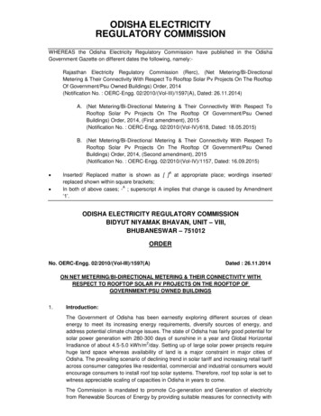
Harmonics Theory Basic Harmonic Theory Harmonics describe disturbances whichrepeat every cycle for a significant number ofcycles Engineers use Fourier notation to describeharmonic waveforms V (t ) 2 (VnSin(n 0t n) )n 1
Harmonics Theory200.060 Hz (Fundamental)300 Hz (5th 0100.0150.0200.0 V (t ) 2 (VnSin(n 0t n) )n 1630720
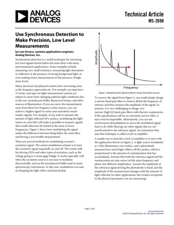
Harmonics Theory150.060Hz (1)180Hz (3)300Hz (5)420Hz (7)540Hz (9)660Hz 150.0Even a square wave can be represented as a series of harmonics.800
Harmonics in Power Repetitive contamination of the voltage orcurrent waveformGenerated by non-linear loads. Voltageharmonics are a reflection of the non-linearload on a distribution system with finiteimpedanceProduce a variety of infrastructural problemsGenerate system lossesCan result in metering errors and disputes
Harmonics – what aren’t they? Sags, dips, swells Transient voltages Frequency variationsThese are all non-periodic kinds of powerquality issues. Harmonics MUST beperiodic, meaning they occur at a giveninterval.
Focus on Harmonics Where do harmonics come from?Non-linear loads at the customer’s site Coupling from loads at other sites sharingthe distribution system One customer’s harmonic current load isconverted into voltage harmonics at othercustomer’s sites by the impedance of thesystem
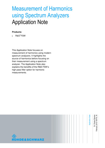
Linear Load – ResistiveIrmsSine 20480540600660720-50-100-150-200DegreesResistors are measured in Ohms. When an AC voltage is applied to a resistor, thecurrent is in degrees. A resistive load is considered a “linear” load because whenthe voltage is sinusoidal the current is sinusoidal.R
Linear Load – InductiveIrmsSine 20480540600660720-50-100-150-200DegreesInductors are measured in Henries. When an AC voltage is applied to an inductor,the current is 90 degrees out of phase. We say the current “lags” the voltage. Ainductive load is considered a “linear” load because when the voltage is sinusoidalthe current is sinusoidal.L
Linear Load – CapacitiveIrmsSine 20480540600660720-50-100-150-200DegreesCapacitors are measured in Farads. When an AC voltage is applied to a capacitor,the current is 90 degrees out of phase. We say the current “leads” the voltage. Acapacitive load is considered a “linear” load because when the voltage issinusoidal the current is sinusoidal.C
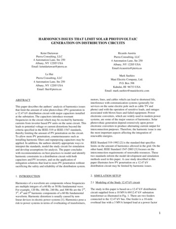
Non-Linear Load – Switching Power SupplyAn AC-DC switching power supply is an example of a non-linear load. The circuituses a diode and switch (normally a transistor or relay) which produces a nonsinusoidal effect on the current as seen in the waveform above.
Total Harmonic Distortion (THD)THD is a measurement of the ratio of the sumof the harmonic power to the power of thefundamental frequency.4 ( n)VT HD 2n 2V1This is an equation for a waveform with 3 harmonics.V1 is the fundamental (60Hz)V2 is the 2nd harmonic (120Hz)V3 is the 3rd harmonic (180Hz)V4 is the 4th fundamental (240Hz)
Total Harmonic Distortion (THD)EXAMPLESFundamental signal (60 Hz) is 10A2nd harmonic (120 Hz) is 0.3A3rd harmonic (180 Hz) is 0.2A4th harmonic (240 Hz) is 0.1ATHD 3.7%Fundamental signal (60 Hz) is 12A2nd harmonic (120 Hz) is 10A3rd harmonic (180 Hz) is 3A4th harmonic (240 Hz) is 1.5ATHD 87.9%It is possible for THD to be greater than 100%, meaning that thesignal has more harmonic energy than fundamental energy!
Past Harmonic SourcesSOURCETYPELEVELTransformer Saturation EnergizationCurrent Harmonics3,5,7 & 2,4 1 to 85%Arc Furnace WeldersVoltage Harmonics5&72.5 to 8%Line CommutatedConvertersVolt. & Cur. HarmonicsH np 110 to 30%Static VAR CompensatorsCurrent HarmonicsH np 12 to 4%Saturable ReactorsCurrent Harmonics3,5,7 1 to 8%
New Harmonic SourcesSOURCEFluorescent LightingElectronic Power SuppliesEspecially ComputersTYPECurrent Harmonics3,5,7 up to 49Current Harmonics3,5,7 up to 25LEVEL 400% 100%
Are Newer Light Bulbs “green”? Big push now underway to move to“green” light bulbs such as CCFL and LEDin place of incandescent CCFL’s and LED’s consume lower W andVA overall for a comparable amount oflightEXCEPT . They generate VARs and a high level ofharmonics!
Green 60W Incandescent BulbActive Power 41WReactive Power 1 VARApparent Power 41VACurrent THD 1.5%
60W Equivalent CCFL BulbActive Power 14 WReactive Power 6 VARApparent Power 16 VACurrent THD 88%
60W Equivalent LED BulbActive Power 11 WReactive Power 4 VARApparent Power 12 VACurrent THD 111%
Laptop Computer Power SupplyActive Power 35 WReactive Power 6 VARApparent Power 37 VACurrent THD 144%
Harmonic TheoryAn Alternate Approach Harmonics can be grouped into “sequences”which help us understand their effects.NameF2nd 3rd 4th 5th 6th 7th 8th 9thFreq60120 180 240 300 360 420 480 540Seq -0 -0 -0
Harmonic TheoryAn Alternate 40300360420480540Seq -0 -0 -0Current Waveform s2.5Pa Current2Pb CurrentPc ositive ( ) If fundamentalrotation is ABC thenpositive ( )sequence harmonicshave ABC rotation
Harmonic TheoryAn Alternate 40300360420480540Seq -0 -0 -0Current Waveforms2Pa CurrentPb CurrentPc ive (-) If fundamentalrotation is ABC thennegative (-) sequenceharmonics have CBArotation
Harmonic TheoryAn Alternate 40300360420480540Seq -0 -0 -0Current Waveforms2Pa CurrentPb CurrentPc Current1.510.500-0.5-1-1.5-260120180240300360ZERO (0) If fundamentalrotation is ABC thenzero (0) sequenceharmonics have NOrotation
Harmonic TheoryAn Alternate Approach Positive ( ) Heating of conductors and transformers Negative (-) Heating of conductors and transformers Tries to make motors run backwards Zero (0) Results in neutral currents which can belarger than phase currents
How do harmonics affect metering? Mechanical meters will not registerharmonics well – 80% error at higherharmonics Solid state meters can measure harmonicswell depending on the sampling rate andVAR calculation used CTs and PTs can only pass a limitedrange of harmonics
Harmonics & Metering Accuracy Primarily affect the calculation of VA, VARand Power Factor No ANSI standard for these calculations atthis time Different manufacturers use different methodsand definitions. Most manufacturers allow the user to makeseveral choices for each Differences of over 50 percent in answers canoccur in high harmonic situations
Harmonics & Metering -5-10-15-20Waveform #1 - 90 Degree Phased Fired WaveformTypical for a light dimmer set to 50%
Harmonics & Metering 00-50-2-100-4-150-6-200-890180Waveform #2 - Quadriform WaveformSwitched Load Device270360
Harmonics & Metering 60090180-50-5-100-10-150-200-15Waveform #3 - Peaked WaveformSwitching Power Supply270360
Harmonics & Metering 36090180-50-5-100-10-150-200-15Waveform #4 - Pulse WaveformSwitching Power Supply270360
Harmonics & Metering 270036090180-2-4-100-6-150-200-8-10Waveform #5 – Multiple Zero Crossing CurrentWaveform270360
Harmonics & Metering 0.00Waveform #6 – Multiple Zero Crossing VoltageWaveform270.00360.00
Harmonic Compensation Harmonics can be compensated for atthe customer’s facility Solution must be tailored to the problem Examples of solutions:Active Filter – mirror image of harmonic Tuned Filter – effective but expensive Zig zag transformer reduces 3rd harmonicsin neutral There is no “one size fits all” solution
IEEE Power Quality Standards SCC-22 Power Quality Standards Coordinating Committee 1159: Monitoring Electric Power Quality 1159.1: Guide for Recorder and Data AcquisitionRequirements 1159.2: Power Quality Event Characterization 1159.3: Data File Format for Power Quality Data Interchange P1564: Voltage Sag Indices 1346: Power System Compatibility with Process Equipment P1100: Power and Grounding Electronic Equipment 1433: Power Quality Definitions P1453: Voltage Flicker 519: Harmonic Control in Electrical Power Equipment P519A: Guide for Applying Harmonic Limits on Power Systems
IEC Power Quality Standards 61000-1-X Definitions and methodology61000-2-X Environment61000-3-X Limits61000-4-X Test and measurements61000-5-X Installation and mitigation61000-6-X Generic immunity and emissions standardsWorking Groups and Committees SC77A Low Frequency EMC PhenomenaTC77/WG1 TerminologySC77A/WG1 Harmonics and other low frequency disturbancesSC77A/WG6 Low frequency Immunity TestsSC77A/WG2 Voltage fluctuations and other low frequency disturbancesSC77A/WG9 Power Quality measurement methods
Questions? Comments?Want a copy of thispresentation?Go tohttps://www.powermetrix.com/presentations/Thank you for your time!
Harmonics in Power Repetitive contamination of the voltage or current waveform Generated by non-linear loads. Voltage harmonics are a reflection of the non-linear load on a distribution system with finite impedance Produce a variety of infrastructural problems Generate system losses Can result in metering errors and disputes