Transcription
Brivo ACS100Installation ManualIntroductionLegal Disclaimers. 2Introduction. 4IIPre-InstallationUnderstand the function of the ACS100. 6Understand ACS100 product compatibility. 6Verify client site is ready for installation. 6Verify shipping contents. 7Planning the installation. 7Follow safety precautions. 8IIIGeneral AssemblyAssemble and mount ACS100. 9If not using PoE. 11IVWiringWiring the ACS100. 12Grounding the ACS100. 15Powering the ACS100. 15Resetting the ACS100 to factory default. 15VConfigurationConnecting to the ACS100 via local area network. 16Verify connection of ACS100 to local area network. 16I
Brivo ACS100 Installation ManualLegal DisclaimersFederal Communications Commission (FCC) CompliancyYou are cautioned that changes or modifications not expressly approved by the part responsible for compliancecould void the user’s authority to operate the equipment.FCC 15B Class BThis equipment has been tested and found to comply with the limits for a Class B digital device, pursuant to part 15of the FCC Rules. These limits are designed to provide reasonable protection against harmful interference in a residential installation. This equipment generates, uses and can radiate radio frequency energy and, if not installed andused in accordance with the instructions, may cause harmful interference to radio communications. However, thereis no guarantee that interference will not occur in a particular installation. If this equipment does cause harmful interference to radio or television reception, which can be determined by turning the equipment off and on, the useris encouraged to try to correct the interference by one or more of the following measures:1.Reorient or relocate the receiving antenna.2.Increase the separation between the equipment and receiver.3.Connect the equipment into an outlet on a circuit different from that to which the receiver is connected.4.Consult the dealer or an experienced radio/TV technician for help.This telecommunication equipment conforms to NTC technical requirement.This device complies with Industry Canada licence-exempt RSS standard(s). Operation is subject to the following twoconditions:(1) this device may not cause interference, and (2) this device must accept any interference, including interferencethat may cause undesired operation of the device.Le présent appareil est conforme aux CNR d’Industrie Canada applicables aux appareils radio exempts de licence.L’exploitation est autorisée aux deux conditions suivantes:(1) l’appareil ne doit pas produire de brouillage, et (2) l’appareil doit accepter tout brouillage radioélectrique subi,même si le brouillage est susceptible d’en compromettre le fonctionnement.Underwriter Laboratories (UL) ComplianceThe ACS100 complies with the UL 294 Standard for access control units.Canada-Underwriters Laboratories (C-UL) Compliancy (CSA C22.2 No. 205)For C-UL Listed applications, the unit shall be installed in accordance with Part 1 of the Canadian Electrical Code. 2021 Brivo Systems LLC. All rights reserved.2P-MAN-PUB-Brivo ACS100 Installation Manual
Brivo ACS100 Installation ManualUL294/ULC Listing CompliancyUL294 Peformance LevelsModelNumberAccess ControlDestructiveLine SecurityAttack LevelLevelEnduranceLevelStand-byPower LevelConditionsLevel 1Level 1N/ABrivo ACS100-E(all threeform factors)Level 1Level 1Parts and ServiceThe ACS100 controller (part numbers listed below) contains no user serviceable parts.ACS100 Part NumbersB-ACS100-E-BSPM-BMullion, Tri-Tech, BlackB-ACS100-E-BSPM-WMullion, Tri-Tech, WhiteB-ACS100-E-BSPS-BSingle-Gang, Tri-Tech, BlackB-ACS100-E-BSPS-WSingle-Gang, Tri-Tech, WhiteB-ACS100-E-BSPK-BKeypad, Tri-Tech, BlackB-ACS100-E-BSPK-WKeypad, Tri-Tech, WhiteB-ACS100-E-BSM-BMullion, Dual-Tech, BlackB-ACS100-E-BSM-WMullion, Dual-Tech, WhiteB-ACS100-E-BSS-BSingle-Gang, Dual-Tech, BlackB-ACS100-E-BSS-WSingle-Gang, Dual-Tech, WhiteB-ACS100-E-BSK-BKeypad, Dual-Tech, BlackB-ACS100-E-BSK-WKeypad, Dual-Tech, WhiteDocumentation Disclaimer and RestrictionsInformation in this document is subject to change without notice and does not represent a commitment on the partof Brivo Systems LLC. For the most up-to-date information, visit www.brivo.com.This document and the data herein shall not be duplicated, used or disclosed to others for procurement or manufacturing, except as authorized with the written permission of Brivo Systems LLC. The information contained withinthis document or within the product itself is considered the exclusive property of Brivo Systems LLC. All informationin this document or within the hardware and software product themselves is protected by the copyright and/orother intellectual property laws of the United States.Product SupportAll support for this product is provided by the third-party dealer. Please contact the dealer who installed the product with questions and support requests. 2021 Brivo Systems LLC. All rights reserved.Brivo is a trademark of Brivo Systems LLC. Brivo Systems LLC., 7700 Old Georgetown Road, Suite 300, Bethesda,MD 20814 2021 Brivo Systems LLC. All rights reserved.3P-MAN-PUB-Brivo ACS100 Installation Manual
Brivo ACS100 Installation ManualIntroductionDocument ObjectivesThis Installation Manual provides step-by-step instructions for installing the Brivo ACS100. Its primary audienceis trained access control installation technicians (Installers) who are responsible for installing the ACS100 at clientsites.The manual is also intended for IT personnel. It may be used by dealers and their sales professionals to help themconduct pre-sales, and to provide client support during the installation process. Finally, it may be used for in-housetraining purposes and ongoing support.Document LayoutThis manual is organized into a series of procedural checklists, detailing steps you must follow to ensure a safe andeffective installation. The main sections of the manual are:Pre-Installation ProceduresGeneral Assembly ProceduresConfiguration ProceduresWiring ProceduresTerminologyThe following is a list of terms that are used throughout this document. While some of these terms may have othermeanings, the definitions provided below are the ones intended in this Installation Manual.Control Panel: Brivo’s one Door Controller (ACS100) is a native Ethernet and Bluetooth enabled accesscontrol panel and reader in a compact form factor. An additional reader can be added for in/out antipass-back configurations.Reader: The ACS100 includes an integrated access control card reader. In addition, the reader has a Bluetooth/BLE radio which constitutes a wireless credential reader compatible with BT enabled smartphones.Access control system (ACS). The complete interaction between a control panel, the Brivo application, andthe Brivo cloud server.Brivo Access: Brivo’s cloud based software application which enables the end user to manage his or herBrivo account.Brivo Cloud Server: The off-site servers, hosted by Brivo, that are used to store an account’s database.Configuration and maintenance of the control panel is managed through Brivo. 2021 Brivo Systems LLC. All rights reserved.4P-MAN-PUB-Brivo ACS100 Installation Manual
Brivo ACS100 Installation ManualWire RecommendationsSignalBelden # orEquivalentAWGTwisted PairShielded?Max LengthPower5504FE22YesYes600 ftPower6300FE18YesYes1500 ftRJ45-EthernetN/ACat5YesYes330 ftRequest-to-Exit5520FE/6300FE22/18YesYes500 ftDoor Contact5500FE22YesYes1500 ftEarth GroundN/A6YesYes20 to 40 ftOptional OSDPReaderN/A24YesYes1000 ftAdditional ResourcesThe following additional resources are available for the installer as well as the client.·····ACS100 Data SheetPanel Networking Admin Interface GuideBrivo Quick Start GuideTechnical Support: 1-866-BRIVO-4-Uwww.brivo.com 2021 Brivo Systems LLC. All rights reserved.5P-MAN-PUB-Brivo ACS100 Installation Manual
Brivo ACS100 Installation ManualPre-Installation ProceduresBefore you begin installing the Brivo control panel, perform the following tasks to ensure a safe, speedy, and successful installation.Understand the function of the Brivo ACS100-E control panelThe ACS100-E is a one door control panel with a single access point. This control panel is considered astandalone system. The control board has one reader on-board. A second reader is supported forsingle door in/out antipassback configurations.The Brivo ACS100-E uses an on-board Ethernet PoE interface to communicate via any TCP/IP networkingtechnology that can be connected through a hub, router or switch, including satellite communications. Itis an IP-enabled Access Control System that interacts with the Brivo cloud server via the Brivo application.Understand Brivo ACS100 product compatibilityThe ACS100 control panel allows for the attachment of one additional reader directly to the ACS100 controlpanel for the purposes of in/out scenarios (anti-passback). As such, the ACS100 is compatible with alarge number of standard OSDP reader models including the following (UL tested for compatibility) readermodels: OSDP reader 921PTPTEK00385. Brivo products are designed to accommodate the latest updates inOSDP using RS-485 reader formats. The ACS100 control board is compatible with OSDP readers usingRS-485.A current list of compatible readers and keypads is maintained on Brivo’s website at www.brivo.com. If youhave a specific model of reader or keypad that is not listed on the Brivo website, please contact TechnicalSupport at 1-866-BRIVO-4-U to determine compatibility.Verify that the client site is ready to support the installation1.Check with the IT department to ensure that the ACS100 to be installed is compatible with thecompany’s local area network (LAN).a)The ACS100 is equipped with a standard RJ-45 socket that accepts a CAT5 cable with an RJ-45 plug on any 10/100 Ethernet network. Physically connecting the panel is the sameas plugging any computer or other device into the LAN.b)Refer to connection instructions or in the Panel Networking Guide for instructions onconnecting to the LAN. The Panel Networking Guide also contains a complete list ofrequirements regarding TCP/IP configuration parameters and information about securityconsiderations.2.Download the Brivo Quick Start Guide from the Brivo website and provide it to the Primary Adminis-trator. This document provides instructions for registering and configuring the control panel in theapplication.3.Make sure the account has been created and the control panel is registered through Brivo. If thecontrol panel has not been registered by the dealer, the installer may either contact Brivo TechnicalSupport for assistance or simply register the panel directly.4.Verify that the Primary Administrator and any other employee who will be accessing the systemhave Internet access on a computer equipped with a supported Web browser. 2021 Brivo Systems LLC. All rights reserved.6P-MAN-PUB-Brivo ACS100 Installation Manual
Brivo ACS100 Installation ManualVerify shipping contents1.Locate and check the contents of the Control Panel kit.The ACS100 kit should contain the following parts:a)1 cardboard box containing the following:·The ACS100 unit, with its identification label on the back·An additional loose label for reference.·A quick start guide·A bag of accessory parts containing:·1 MOV (Metal Oxide Varistor)·2 120 ohm RS-485 bus termination resistors.·Back mounting metal plate and attachment screw·Pigtail cable with connections for door I/O and optional external readerPlan your installation and decide where to install the ACS1001.If not using Power Over Ethernet (PoE), do not place the ACS100 more than 100 feet from thetransformer. This is the maximum cable run allowed by most external power supplies.a)Calculate the distance between the ACS100 and its associated keypad or reader. The ACS100does not specify a maximum distance between the ACS100 and a keypad or reader, but thekeypad/reader manufacturer does. Follow manufacturer guidelines for each keypadand reader.b)Place the ACS100 within 50 feet of its associated electronic strike or latch. 2021 Brivo Systems LLC. All rights reserved.7P-MAN-PUB-Brivo ACS100 Installation Manual
Brivo ACS100 Installation ManualFollow safety precautionsWARNING: Fire CodeNever connect a keypad/reader or lock to doors without first consulting the applicable fire code. You must consultwith, and get approval from, local fire officials before installing locks or devices on any doors that may be fire exits.Use of egress push buttons may not be legal. Single action exits may be required. Always obtain proper permits andapprovals in writing before installing equipmentWARNING: Fail Secure ModeDo not install the system in the fail secure mode unless permitted by the local authority having jurisdiction. Doingso may cause interference with the operation of panic hardware.WARNING: Heat and NoiseDo not install the control panel in an area that could drop below -40 degrees FAHRENHEIT or exceed 140 degrees (ifusing PoE) or 150 degrees (if using 12VDC). Doing so can cause damage to components within the control panel.Do not install the control panel near or on the same circuit with devices that produce large amounts of electricalnoise. This includes grinders, electric motors and blowers, electrical switch-gear and other electrically noisy equipment. Electrical noise can interfere with panel operation. If it is not possible to install the panel away from suchsources of noise, it is advisable to isolate it by using a high-quality UPS (Uninterruptible Power Supply) between theAC Mains and the transformer.·Unit is for indoor and outdoor use.·Power wiring attached to the ACS100 unit should be 22 AWG or larger.·Category 5 cabling is the minimum performance category recommended.·Do not connect to a receptacle controlled by a switch.·Compliance with IEEE 802.3 (at or af) specifications was not verified as part of UL294/B.·If powered by 12VDC, the power supply must be a UL294 listed or UL 603 listed power supply.Battery capacity for loss of primary power at least zero (0) hours. 2021 Brivo Systems LLC. All rights reserved.8P-MAN-PUB-Brivo ACS100 Installation Manual
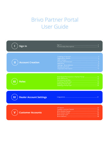
Brivo ACS100 Installation ManualGeneral Assembly ProceduresMullionFull-SizeKeypadAssemble and mount ACS1001.Mount the ACS100 unit using one of the two methods described below.a)If using ACS100 mullion:i)Use two bolts on the back of the ACS100 unit to mount the ACS100 unit securely inplace.ACS100 Mullion Mounting 2021 Brivo Systems LLC. All rights reserved.9P-MAN-PUB-Brivo ACS100 Installation Manual
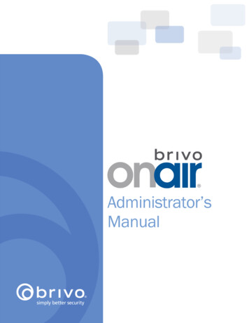
Brivo ACS100 Installation Manualb.If using ACS100 full size or keypad:i)Looking at the back of the ACS100 unit, use two bolts to mount the ACS100 unit to ajunction box.ACS100 Full Size or Keypad Mountingc.If mounting the ACS100 unit on an exterior wall surface that will receive rain or moisture, runa bead of sealant around the back edge of the unit where it meets the walls. 2021 Brivo Systems LLC. All rights reserved.10P-MAN-PUB-Brivo ACS100 Installation Manual
Brivo ACS100 Installation ManualOPTIONAL: If not using Power over Ethernet, wire the 12 V In (Orange) and Ground (Black) wires to an external12 VDC Power Supply1.Use 18 AWG wire (minimum grade) to connect the appropriate input power wires to the ACS100unit.Connecting optional External Power to the ACS100ModelCircuitVoltage (VDC)Current (A)Brivo ACS100-EInput12VDC900mA 2021 Brivo Systems LLC. All rights reserved.11P-MAN-PUB-Brivo ACS100 Installation Manual
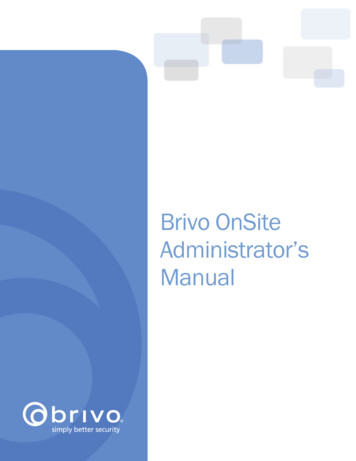
Brivo ACS100 Installation ManualWiring ProceduresProvided below is a Wire Block diagram for the ACS100 unit.NOTE: The ACS100 has a pair of RS-485 wires for connecting an optional external OSDP Reader. The ACS100 cansupport one wired lock with up to two readers (one internal and one optional external).For the ACS100 unit to be used for controlling a door, make the following connections:ACS100 Pigtail Wiring DescriptionACS100 Wire BlockWire the REX & DOOR CONTACT (DC)1.Connect the Normally Open (NO) contacts of the REX device to the REX (Blue) and Ground(Black) wires.a)2.When this switch closes, it initiates a Request-to-Exit (REX) program sequence, asdefined by the appropriate application, including the option to activate the door orother relays, fire the door strike, and suppress any “Door Forced” messages.Connect the Normally Closed (NC) contacts of the Door Contact (DC) to the DC(Yellow) and Ground (Black) wires.a)In this context, an NC switch is considered closed when the door is closed (magnet ispresent), and open when the door is open (no magnet is present). 2021 Brivo Systems LLC. All rights reserved.12P-MAN-PUB-Brivo ACS100 Installation Manual
Brivo ACS100 Installation Manualb)c)When the switch is open, the control panel interprets this input as a “Door Open”condition. When the switch is closed, the control panel interprets this input as a“Door Closed” condition.This circuit provides door status information (open/closed) to the control panel sothe Brivo Cloud Server can take appropriate action locally, or send emailnotifications if necessary.Wire the DOOR LOCK RELAY1.Using the output 12VDC and the Switched Ground, Door Strikes and Magnetic Locks can bedirectly powered. In the use case of a Door Strike, the strike is connected to the ACS100’s 12VDC and the Switched Ground. The Switched Ground can be configured as Normally Open(Normal) or Normally Closed (Energized) depending on the lock utilized. In this scenario, theACS100 can switch up to 3A@12VDC.2.For situations requiring a 24 VDC lock, an external power source can be used to power thelock, use a shared ground between the power source and the ACS100, and then use theSwitched Ground to power the lock or solenoid. In this scenario, the ACS100 can drive up to3A@24VDC (note that the ACS100 should be powered from PoE or 12 VDC power supply).3.Devices which require a switched ground to externally drive an external device (such as a PIRsensor turning on and off a mag lock) can use the Switched Ground directly. It can pull650mA via the 12V output up to 104 degrees Fahrenheit (40 degrees C).4.Devices which require a switched 12V trigger (low power signalling) to turn on and off thelock can configure the ACS100 to use the 12V trigger. Note that in this scenario, the Brownwire is pulled high to 12V to use as a trigger, but won’t be able to source power.5.From the Brivo user interface, the ACS100 door lock relay default state can be configuredin software as Normal or Energized. In addition to the default state selection, an installer isalso able to select the Output Mode with the options of Lock Power or Lock Trigger.·Lock Power refers to the Switched Ground connection which may be used toenergize or de-energize locks.·Lock Trigger refers to the 12VDC Trigger which shares a common connectionwith the Switched Ground. It may be used as a low power input signal to anexternal power control device.Lock Power Wiring Diagram 2021 Brivo Systems LLC. All rights reserved.13P-MAN-PUB-Brivo ACS100 Installation Manual
Brivo ACS100 Installation Manual6.Connect the ACS100 12 V Out (Red) to the positive side of the Door Lock Relay.7.Connect the ACS100 Switched Ground (Brown) to the negative side of the Door Lock Relay.Wire the AUXILIARY INPUT (AUX)1.There are three (3) Supervised Inputs: Request To Exit (REX), Door Contact (DC), and AuxiliaryInput (AUX). The Inputs can be configured as:·Two (2) State (non-supervised) with Closed / Open Status.·Four (4) State (use of two 2Kohm End of Line Resistors) supervised with Closed /Open / Short / Cut Status.2.If used, wire the Aux Input using the Purple (AUX) wire and the Ground (Black) wire. The AuxInput can be used for a variety of purposes, and is programmed through the Brivo program-ming interface.WARNING: Noise Suppression1.Install the MOV across the conductors, as close as possible to the electric strike, latch, ormagnetic lock. This will normally be at the connection from the field-installed wiring to thepigtail or screw terminals of the electronic strike, latch, or magnetic lock.2.Use the wire recommended by the manufacturer of the electric strike or latch. If nowire is recommended, use a minimum of 18 AWG wire with sufficient strandsfor the specific electronic strike or latch.Wire the optional SECOND READER1.If you are using an optional external OSDP reader, connect the wire properly to the pigtail.Following is a typical, but not universal, wiring guide.a)Connect the wire to the RS485A (Green) wire. This is the standard RS485A circuit forOSDP readers using RS-485.b)Connect the wire to the RS485B (White) wire. This is the standard RS485B circuit forOSDP readers using RS-485.c)Connect the wire to the Ground (Black) wire. This is the standard Ground circuit forthe reader.d)Connect the wire to the 12V Out (Red) wire. This provides 12VDC to power thereader.NOTE: The ACS100 unit only supports RS485 Half-Duplex mode of operation. 2021 Brivo Systems LLC. All rights reserved.14P-MAN-PUB-Brivo ACS100 Installation Manual
Brivo ACS100 Installation ManualIMPORTANT RS-485 WIRING INFORMATIONNOTE: If the external OSDP reader is a significant distance from the ACS100 unit, then it is recommended that bothends of the RS-485 bus are terminated using a 120 ohm resistor.NOTE: When wiring the RS-485 bus, use only twisted pair shielded wire.Ground the ACS1001.When grounding the ACS100 unit, use 18 AWG or larger wire to connect the ACS100 to a suitableearth ground.Power up the ACS100NOTE: The ACS100 is UL listed when using DC power.1.Ensure that all wiring is complete prior to powering up the ACS100 unit.2.Plug the CAT 5 cable into the LAN/PoE connector.3.If not using PoE, plug in power to the ACS100 unit using 12 V In (Orange) and Ground (Black).4.Confirm after a few seconds that the Brivo logo light is on.5.If after verifying that the unit is powered and the Brivo logo does not illuminate, contactTechnical Support.6.Optionally, you may use PoE and an external 12V power supply for redundant simultaneous powerinput.Resetting the ACS100 to factory defaultAn ACS100 unit goes into a factory default reset sequence when it is held upside down, powered up and thefollowing steps are performed:1.With the power off, hold the unit upside down.2.Power up the ACS100 unit.3.For between 1-3 seconds, turn the unit right side up.4.For between 1-3 seconds, reverse the unit upside down again.5.For between 1-3 seconds, reverse the unit right side up again.6.After the third reversal, the ACS100 will recognize that factory reset is desired and will initiate thefactory default reset procedure. The ACS00 reader/controller will execute a visual LED and audiobeep sequence to indicate completion of the factory default reset.NOTE: The ACS100 reader/controller does not have a physical factory default reset (FDR) button. 2021 Brivo Systems LLC. All rights reserved.15P-MAN-PUB-Brivo ACS100 Installation Manual
Brivo ACS100 Installation ManualConfiguration ProceduresIf any manual configuration is required, connect a laptop to the same local area network as the ACS100 unitNOTE: The laptop and ACS100 unit MUST be on the same subnet.1.Set your NIC interface on your laptop/PC to IP 169.254.242.122 and net mask 255.255.255.0 .2.3.Connect the CAT5 cable from the NIC interface on the laptop to PoE network switch.Connect another CAT5 cable from PoE network switch to ACS100 unit. Allow a few seconds for theACS100 unit to boot up.4.Open a web browser and navigate to 169.254.242.121 .5.When the prompt appears for username/password, use username cli and password new5cli.a)The Administrative Interface (WebCLI) is used to gain access to the onboard functionality fordebugging and manual configuration utilities.Verify connection of the LAN to the ACS1001.Using CAT5 cable, connect the LAN to the ACS100 unit via its LAN port.a)The LAN port is a 10/100 Ethernet interface with an RJ45 jack for connecting the Ethernetport on the back of the ACS100 to a Local Area Network in order for it to gain connectivity tothe Internet.b)Use a straight, (i.e., non-crossover) cable to connect this port to a local hub, switch or router.2.Verify the connection of the LAN to the ACS100 by accessing the Administrative Interface (WebCLI)using the instructions listed in the previous step. On the main page of the Administrative Interface,you should see a recent time/date stamp in the Last Contact with Central field.NOTE: Firmware Upgrade - When first registered and connected to the Brivo cloud service, your ACS100 will automatically download and install the latest firmware. This process may take several minutes, so do not disconnect orcut power to your ACS100 during this process. If you encounter any difficulties during this process, please contactBrivo Technical Support at 866-274-8648 or email customercare@brivo.com.Revision TableVersionDateContent1.001/22/2020Original document1.101/23/2020Updated with requested changes byWavelynx1.203/12/2020Added note for UL1.304/17/2020Added part numbers on Page 3, updatedWiring Procedures, compliance language,and firmware upgrade language1.410/26/2020Corrected typo on Page 81.502/23/2021Added factory default instructions 2021 Brivo Systems LLC. All rights reserved.16P-MAN-PUB-Brivo ACS100 Installation Manual
Brivo ACS100-E (all three form factors) Level 1 Level 1 Level 1 Level 1 N/A Parts and Service The ACS100 controller (part numbers listed below) contains no user serviceable parts. ACS100 Part Numbers B-ACS100-E-BSPM-B Mullion, Tri-Tech, Black B-ACS100-E-BSPM-W Mullion, Tri-Tech, White