Transcription
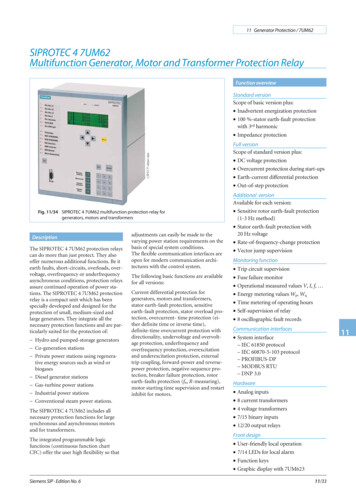
11 Generator Protection / 7UM62SIPROTEC 4 7UM62Multifunction Generator, Motor and Transformer Protection RelayFunction overviewLSP2171-afpen.epsStandard versionScope of basic version plus: Inadvertent energization protection 100 %-stator earth-fault protectionwith 3rd harmonic Impedance protectionFig. 11/34 SIPROTEC 4 7UM62 multifunction protection relay forgenerators, motors and transformersDescriptionThe SIPROTEC 4 7UM62 protection relayscan do more than just protect. They alsooffer numerous additional functions. Be itearth faults, short-circuits, overloads, overvoltage, overfrequency or underfrequencyasynchronous conditions, protection relaysassure continued operation of power stations. The SIPROTEC 4 7UM62 protectionrelay is a compact unit which has beenspecially developed and designed for theprotection of small, medium-sized andlarge generators. They integrate all thenecessary protection functions and are particularly suited for the protection of: Hydro and pumped-storage generators Co-generation stations Private power stations using regenerative energy sources such as wind orbiogases Diesel generator stations Gas-turbine power stations Industrial power stations Conventional steam power stations.The SIPROTEC 4 7UM62 includes allnecessary protection functions for largesynchronous and asynchronous motorsand for transformers.The integrated programmable logicfunctions (continuous function chartCFC) offer the user high flexibility so thatSiemens SIP · Edition No. 6adjustments can easily be made to thevarying power station requirements on thebasis of special system conditions.The flexible communication interfaces areopen for modern communication architectures with the control system.The following basic functions are availablefor all versions:Current differential protection forgenerators, motors and transformers,stator earth-fault protection, sensitiveearth-fault protection, stator overload protection, overcurrent- time protection (either definite time or inverse time),definite-time overcurrent protection withdirectionality, undervoltage and overvoltage protection, underfrequency andoverfrequency protection, overexcitationand underexcitation protection, externaltrip coupling, forward-power and reversepower protection, negative-sequence protection, breaker failure protection, rotorearth-faults protection (fn, R-measuring),motor starting time supervision and restartinhibit for motors.Full versionScope of standard version plus: DC voltage protection Overcurrent protection during start-ups Earth-current differential protection Out-of-step protectionAdditional versionAvailable for each version: Sensitive rotor earth-fault protection(1-3 Hz method) Stator earth-fault protection with20 Hz voltage Rate-of-frequency-change protection Vector jump supervisionMonitoring function Trip circuit supervision Fuse failure monitor Operational measured values V, I, f, Energy metering values Wp, Wq Time metering of operating hours Self-supervision of relay 8 oscillographic fault recordsCommunication interfaces11 System interface– IEC 61850 protocol– IEC 60870-5-103 protocol– PROFIBUS-DP– MODBUS RTU– DNP 3.0Hardware Analog inputs 8 current transformers 4 voltage transformers 7/15 binary inputs 12/20 output relaysFront design User-friendly local operation 7/14 LEDs for local alarm Function keys Graphic display with 7UM62311/33
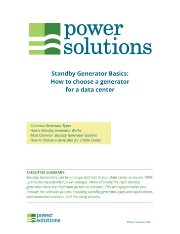
11 Generator Protection / 7UM62ApplicationThe 7UM6 protection relays of theSIPROTEC 4 family are compact multifunction units which have been developedfor small to medium-sized power generation plants. They incorporate all the necessary protective functions and are especiallysuitable for the protection of:Generator BasicOne application concentrates on small andmedium generators for which differentialprotection is required. The function mix isalso suitable as backup protection. Protection of synchronous motors is a further application.Generator Standard– Hydro and pumped-storage generators– Co-generation stations– Private power stations using regenerative energy sources such as wind orbiogases– Power generation with dieselgenerators– Gas turbine power stations– Industrial power stations– Conventional steam power stations.In the case of medium-size generators(10 to 100 MVA) in a unit connection, thisscope of functions offers all necessaryprotection functions. Besides inadvertentenergization protection, it also includespowerful backup protection for the transformer or the power system. The scope ofprotection is also suitable for units in thesecond protection group.They can also be employed for protectionof motors and transformers.Here, all protection functions are availableand the main application focuses on largeblock units (more than 100 MVA). Thefunction mix includes all necessary protection functions for the generator as well asbackup protection for the block transformer including the power system. Additional functions such as protection duringstart-up for generators with starting converters are also included.The numerous other additional functionsassist the user in ensuring cost-effectivesystem management and reliable powersupply. Measured values display currentoperating conditions. Stored status indications and fault recording provide assistancein fault diagnosis not only in the event of adisturbance in generator operation.Combination of the units makes it possibleto implement effective redundancy concepts.Generator FullThe scope of functions can be used for thesecond protection group, and functionsthat are not used, can be masked out.ConstructionThe SIPROTEC 4 units have a uniformdesign and a degree of functionality whichrepresents a whole new quality in protection and control.Local operation has been designed according to ergonomic criteria. Large, easy-toread displays were a major design aim. The7UM623 is equipped with a graphic displaythus providing and depicting more information especially in industrial applications. The DIGSI 4 operating programconsiderably simplifies planning and engineering and reduces commissioning times.The 7UM621 and 7UM623 are configuredin 1/2 19 inches width. This means that theunits of previous models can be replaced.The height throughout all housing widthincrements is 243 mm.All wires are connected directly or bymeans of ring-type cable lugs. Alternatively, versions with plug-in terminals arealso available. These permit the use ofprefabricated cable harnesses.In the case of panel surface mounting, theconnecting terminals are in the form ofscrew-type terminals at top and bottom.The communication interfaces are alsoarranged on the same sides.11Numerous protection functions are necessary for reliable protection of electrical machines. Their extent and combination aredetermined by a variety of factors, such asmachine size, mode of operation, plantconfiguration, availability requirements,experience and design philosophy.Besides differential protection, this function package includes all protection functions needed to protect large asynchronousmotors (more than 1 MVA). Stator andbearing temperatures are measured by aseparate thermo-box and are transmittedserially to the protection unit for evaluation.This results in multifunctionality, which isimplemented in outstanding fashion bynumerical technology.TransformerIn order to satisfy differing requirements,the combination of functions is scalable(see Table 11/3). Selection is facilitated bydivision into five groups.11/34This scope of functions not only includesdifferential and overcurrent protection,but also a number of protection functionsthat permit monitoring of voltage and frequency stress, for instance. The reversepower protection can be used for energyrecovery monitoring of ynchronous motorProtection functionsFig. 11/35Rear view with wiring terminalsafety cover and serial interfaceSiemens SIP · Edition No. 6
11 Generator Protection / 7UM62Protection functionsProtection functionsAbbreviationANSI orAsynchronousTransformerCurrent differential protectionΔI87G/87T/87MXXXXXStator earth-fault protectionnon-directional, directionalV0 , 3I0 \(V0, 3I0)59N, 64G67GXXXXXSensitive earth-fault protection(also rotor earth-fault protection)IEE 50/51GN(64R)XXXXXXSensitive earth-fault prot. B (e.g. shaft current prot.)IEE-B IEE-B 51GNXXXXStator overload protectionIt49XXXXXDefinite-time overcurrent prot. with undervolt. seal-inI V 51XXXXXDefinite-time overcurrent protection, directionalI , Direc.50/51/67XXXXXInverse-time overcurrent protectiont f (I) V 51VXXXXXOvervoltage protectionV 59XXXXX2Undervoltage protectionV , t f (V)27XXXXXFrequency protectionf , f 81XXXXXReverse-power protection-P32RXXXXXOverexcitation protection (Volt/Hertz)V/f24XXXXXFuse failure monitorV2/V1, I2/I160FLExternal trip couplingIncoup.Trip circuit supervisionT.C.S.Forward-power protectionUnderexcitation protection (loss-of-field protection)Negative-sequence protectionBreaker failure protectionXXXXX4444474TCXXXXXP , P 32FXXXXX1/xd40XXXI2 , t f (I2)46XXXXImin 50BFXXXX2Motor starting time supervisionIstart tRestart inhibit for motorsIt248XXXX66, 49 RotorXXXXXRotor earth-fault protection (fn, R-measuring)R 64R (fn)Inadvertent energization protectionI , V 50/27100 % stator earth-fault protectionrdwith 3 harmonicsV0(3rd harm.)59TN, 27TN 3hrdXXXXXXImpedance protection with (I V ) pickupZ 21XXInterturn protectionUInterturn 59N(IT)XXDC voltage / DC current time protectionVdc Idc 59N (DC)51N (DC)XOvercurrent protection during startup(for gas turbines)I 51XEarth-current differential protectionΔIe87GN/TNOut-of-step protectionΔZ/Δt78Rotor earth-fault protection (1-3 Hz square wave voltage)100 % stator earth-fault protection with 20 Hz voltageRate-of-frequency-change protectionVector jump supervision (voltage)RREF RSEF df/dt X64R (1–3 Hz)64G (100 %)81RX1)X1)XX1)XThreshold supervisionXX1)X1)1)X1)XX1)1)Δ n of phase rotationA, B, C47XXXXXUndercurrent via CFCI 37XXXXX38XXXXXExternal temperature monitoring via serial interface(Thermo-box)Table 11/3 Scope of functions of the 7UM621) Optional for all function groups.Siemens SIP · Edition No. 611/35
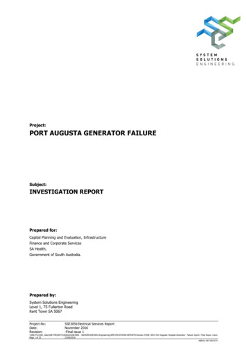
11 Generator Protection / 7UM62Protection functionsCurrent differential protection(ANSI 87G, 87M, 87T)This function provides undelayed short-circuit protection for generators, motors andtransformers, and is based on the currentdifferential protection principle (Kirchhoff’scurrent law).The differential and restraint (stabilization)current are calculated on the basis of thephase currents. Optimized digital filters reliably attenuate disturbances such as aperiodic component and harmonics. The highresolution of measured quantities permitsrecording of low differential currents (10 %of IN) and thus a very high sensitivity.An adjustable restraint characteristic permits optimum adaptation to the conditionsof the protected object. Software is used tocorrect the possible mismatch of the currenttransformers and the phase angle rotationthrough the transformer (vector group).Thanks to harmonic analysis of the differential current, inrush (second harmonic) andoverexcitation (fifth harmonic) are reliablydetected, and unwanted operation of thedifferential protection is prevented. Thecurrent of internal short-circuits is reliablymeasured by a fast measuring stage(IDiff ), which operates with two mutuallycomplementary measuring processes. Anexternal short-circuit with transformer saturation is picked up by a saturation detectorwith time and status monitoring. It becomesactive when the differential current (IDiff)moves out of the add-on restraint area.11If a motor is connected, this is detected bymonitoring the restraint current and therestraint characteristic is briefly raised.This prevents false tripping in the event ofunequal current transmission by the current transformers.Figure 11/36 shows the restraintcharacteristic and various areas.Earth-current differential protection(ANSI 87GN, 87TN)The earth-current differential protectionpermits high sensitivity to single-pole faults.The zero currents are compared. On the onehand, the zero-sequence current is calculated on the basis of the phase currents andon the other hand, the earth current is measured directly at the star-point currenttransformer.11/36Fig. 11/36 Restraint characteristic of current differential protectionFig. 11/37 Restraint characteristic of earth-current differential protectionThe differential and restraint quantity isgenerated and fitted into the restraintcharacteristic (see Fig. 11/37).DC components in particular are suppressed by means of specially dimensionedfilters. A number of monitoring processes avoid unwanted operation in the eventof external short-circuits. In the case of asensitive setting, multiple measurementensures the necessary reliability.However, attention must be drawn to thefact that the sensitivity limits are determinedby the current transformers.The protection function is only used ongenerators when the neutral point isearthed with a low impedance. In the caseof transformers, it is connected on the neutral side. Low impedance or solid earthingis also required.Siemens SIP · Edition No. 6
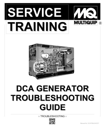
11 Generator Protection / 7UM62Protection functionsDefinite-time overcurrent protectionI , I (ANSI 50, 51, 67)This protection function comprises theshort-circuit protection for the generatorand also the backup protection for upstream devices such as transformers orpower system protection.An undervoltage stage at I maintains thepickup when, during the fault, the currentdrops below the threshold. In the event of avoltage drop on the generator terminals, thestatic excitation system can no longer besufficiently supplied. This is one reason forthe decrease of the short-circuit current.The I stage can be implemented ashigh-set instantaneous trip stage. With theintegrated directional function it can beused as backup protection on the transformer high-voltage side. With the information of the directional element,impedance protection can be controlledvia the CFC.Inverse-time overcurrent protection(ANSI 51V)This function also comprises short-circuitand backup protection and is used forpower system protection with currentdependent protection devices.Fig. 11/38 Characteristic of negative-sequence protectionStator overload protection (ANSI 49)Negative-sequence protection (ANSI 46)The task of the overload protection is toprotect the stator windings of generatorsand motors from high, continuous overload currents. All load variations are evaluated by a mathematical model. Thethermal effect of the r.m.s. current valueforms the basis of the calculation.This conforms to IEC 60255-8.In dependency of the current, the coolingtime constant is automatically extended. Ifthe ambient temperature or the temperature of the coolant are injected via a transducer (TD2) or PROFIBUS-DP, the modelautomatically adapts to the ambient conditions; otherwise a constant ambient temperature is assumed.Asymmetrical current loads in the threephases of a generator cause a temperaturerise in the rotor because of the negativesequence field produced.IEC and ANSI characteristics can beselected (Table 11/4).This protection detects an asymmetricalload in three-phase generators. It functionson the basis of symmetrical componentsand evaluates the negative sequence of thephase currents. The thermal processes aretaken into account in the algorithm andform the inverse characteristic. In addition,the negative sequence is evaluated by an independent stage (alarm and trip) which issupplemented by a time-delay element (seeFigure 11/38). In the case of motors, theprotection function is also used to monitora phase failure.The current function can be controlled byevaluating the generator terminal voltage.Available inverse-time characteristicsCharacteristicsANSIIEC 60255-3The “controlled” version releases thesensitive set current stage.Inverse Moderately inverse With the “restraint” version, the pickupvalue of the current is lowered linearly withdecreasing voltage.Very inverse Extremely inverse Definite inverse The fuse failure monitor preventsunwanted operation.Table 11/4Underexcitation protection(Loss-of-field protection) (ANSI 40)Derived from the generator terminal voltageand current, the complex admittance is calculated and corresponds to the generatordiagram scaled in per unit. This protectionprevents damage due to loss of synchronismresulting from underexcitation. The protection function provides three characteristicsfor monitoring static and dynamic stability.Via a transducer, the excitation voltage (seeFigure 11/52) can be injected and, in theevent of failure, a swift reaction of the protection function can be achieved by timerchangeover.Siemens SIP · Edition No. 611The straight-line characteristics allow theprotection to be optimally adapted to thegenerator diagram (see Figure 11/39). Theper-unit-presentation of the diagram allowsthe setting values to be directly read out.The positive-sequence systems of currentand voltage are used to calculate the admittance. This ensures that the protection always operates correctly even with asymmetrical network conditions.If the voltage deviates from the rated voltage, the admittance calculation has the advantage that the characteristics move in thesame direction as the generator diagram.11/37
11 Generator Protection / 7UM62Protection functionsReverse-power protection (ANSI 32R)The reverse-power protection monitors thedirection of active power flow and picks upwhen the mechanical energy fails. Thisfunction can be used for operational shutdown (sequential tripping) of the generator but also prevents damage to the steamturbines. The reverse power is calculatedfrom the positive-sequence systems of current and voltage. Asymmetrical power system faults therefore do not cause reducedmeasuring accuracy. The position of theemergency trip valve is injected as binaryinformation and is used to switch betweentwo trip command delays. When appliedfor motor protection, the sign ( ) of theactive power can be reversed via parameters.Fig. 11/39Characteristic of underexcitationprotectionFig. 11/40Forward-power protection (ANSI 32F)Monitoring of the active power producedby a generator can be useful for starting upand shutting down generators. One stagemonitors exceeding of a limit value, whileanother stage monitors falling below another limit value. The power is calculatedusing the positive-sequence component ofcurrent and voltage. The function can beused to shut down idling motors.Impedance protection (ANSI 21)11tions and prevents the voltage-related instability of such machines.Overexcitation protection Volt/Hertz(ANSI 24)The function can also be used for monitoring purposes.The overexcitation protection serves for detection of an unpermissible high induction(proportional to V/f) in generators or transformers, which leads to thermal overloading. This may occur when starting up,shutting down under full load, with weaksystems or under isolated operation. The inverse characteristic can be set via eightpoints derived from the manufacturer data.Overvoltage protection (ANSI 59)This protection prevents insulation faultsthat result when the voltage is too high.This fast short-circuit protection protectsthe generator and the unit transformer andis a backup protection for the power system.This protection has two settable impedancestages; in addition, the first stage can beswitched over via binary input. With the circuit-breaker in the “open” position the impedance measuring range can be extended(see Figure 11/40).Either the maximum line-to-line voltagesor the phase-to-earth voltages (for lowvoltage generators) can be evaluated. Themeasuring results of the line-to-line voltages are independent of the neutral pointdisplacement caused by earth faults. Thisfunction is implemented in two stages.The overcurrent pickup element withundervoltage seal-in ensures a reliablepickup and the loop selection logic ensuresa reliable detection of the faulty loop. Withthis logic it is possible to perform correctmeasurement via the unit transformer.The frequency protection prevents impermissible stress of the equipment (e.g. turbine) in case of under or overfrequency. Italso serves as a monitoring and control element.Undervoltage protection (ANSI 27)The undervoltage protection evaluates thepositive-sequence components of the voltages and compares them with the thresholdvalues. There are two stages available.The undervoltage function is used for asynchronous motors and pumped-storage sta-11/38Frequency protection (ANSI 81)In addition, a definite-time alarm stageand an instantaneous stage can be used.For calculation of the V/f ratio, frequencyand also the highest of the three line-toline voltages are used. The frequency rangethat can be monitored comprises 11 to69 Hz.The function has four stages; the stages canbe implemented either as underfrequencyor overfrequency protection. Each stagecan be delayed separately.Even in the event of voltage distortion, thefrequency measuring algorithm reliablyidentifies the fundamental waves and determines the frequency extremely precisely.Frequency measurement can be blocked byusing an undervoltage stage.Siemens SIP · Edition No. 6
11 Generator Protection / 7UM62Protection functions90 % stator earth-fault protection, non-directional, directional (ANSI 59N, 64G, 67G)Earth faults manifest themselves in generators that are operated in isolation by theoccurence of a displacement voltage. In caseof unit connections, the displacement voltage is an adequate, selective criterion forprotection.For the selective earth-fault detection, thedirection of the flowing earth current has tobe evaluated too, if there is a direct connection between generator and busbar.The protection relay measures the displacement voltage at a VT located at the transformer star point or at the broken deltawinding of a VT As an option, it is also possible to calculate the zero-sequence voltagefrom the phase-to-earth voltages.Depending on the load resistor selection, 90to 95 % of the stator winding of a generatorcan be protected.A sensitive current input is available forearth-current measurement. This inputshould be connected to a core-balance current transformer. The fault direction is deduced from the displacement voltage andearth current. The directional characteristic(straight line) can be easily adapted to thesystem conditions. Effective protection fordirect connection of a generator to a busbarcan therefore be established. During startup, it is possible to switch over from the directional to the displacement voltage measurement via an externally injected signal.Depending on the protection setting,various earth-fault protection concepts canbe implemented with this function(see Figures 11/51 to 11/54).Sensitive earth-fault protection(ANSI 50/51GN, 64R)The sensitive earth-current input can alsobe used as separate earth-fault protection. Itis of two-stage form. Secondary earth currents of 2 mA or higher can be reliably handled.Alternatively, this input is also suitable asrotor earth-fault protection. A voltage withrated frequency (50 or 60 Hz) is connectedin the rotor circuit via the interface unit7XR61. If a higher earth current is flowing,a rotor earth fault has occurred. Measuringcircuit monitoring is provided for this application (see Figure 11/56).Siemens SIP · Edition No. 6Fig. 11/41Logic diagram of breakerfailure protection100 % stator earth-fault protection with 3harmonic (ANSI 59TN, 27TN (3 H.))Inadvertent energization protection(ANSI 50, 27)Owing to the creative design, the generatorproduces a 3rd harmonic that forms a zerophase-sequence system. It is verifiable by theprotection on a broken delta winding or onthe neutral transformer. The magnitude ofthe voltage amplitude depends on the generator and its operation.This protection has the function of limitingthe damage of the generator in the event ofan unintentional switch-on of the circuitbreaker, whether the generator is standingstill or rotating without being excited orsynchronized. If the power system voltage isconnected, the generator starts as an asynchronous machine with a large slip and thisleads to excessively high currents in therotor.rdrdIn the event of an earth fault in the vicinityof the neutral point, there is a change in theamplitude of the 3rd harmonic voltage(dropping in the neutral point and rising atthe terminals).Depending on the connection the protection must be set either as undervoltage orovervoltage protection. It can also be delayed. So as to avoid overfunction, the activepower and the positive-sequence voltage actas enabling criteria.The picked-up threshold of the voltage stageis restrained by the active power. This increases sensitivity at low load.The final protection setting can be madeonly by way of a primary test with the generator.Breaker failure protection (ANSI 50BF)In the event of scheduled downtimes or afault in the generator, the generator can remain on line if the circuit-breaker is defective and could suffer substantial damage.Breaker failure protection evaluates a minimum current and the circuit-breaker auxiliary contact. It can be started by internalprotective tripping or externally via binaryinput. Two-channel activation avoidsoverfunction (see Figure 11/41).A logic circuit consisting of sensitive current measurement for each phase, measured value detector, time control andblocking as of a minimum voltage, leads toan instantaneous trip command. If the fusefailure monitor responds, this function isineffective.Rotor earth-fault protection (ANSI 64R)This protection function can be realized inthree ways with the 7UM62. The simplestform is the method of rotor-current measurement (see sensitive earth-current measurement).Resistance measurement at systemfrequency voltageThe second form is rotor earth resistancemeasurement with voltage at system frequency (see Fig. 11/56). This protectionmeasures the voltage injected and the flowing rotor earth current. Taking into account the complex impedance from thecoupling device (7XR61), the rotor earthresistance is calculated by way of a mathematical model. By means of this method,the disturbing influence of the rotor earthcapacitance is eliminated, and sensitivity isincreased. Fault resistance values up to30 kΩ can be measured if the excitationvoltage is without disturbances. Thus, atwo-stage protection function, which features a warning and a tripping stage, can berealized. An additionally implemented undercurrent stage monitors the rotor circuitfor open circuit and issues an alarm.11/3911
11 Generator Protection / 7UM62Protection functionsResistance measurement with a square wavevoltage of 1 to 3 HzA higher sensitivity is required for largergenerators. On the one hand, the disturbinginfluence of the rotor earth capacitancemust be eliminated more effectively and, onthe other hand, the noise ratio with respectto the harmonics (e.g. sixth harmonic) ofthe excitation equipment must be increased.Injecting a low-frequency square wave voltage into the rotor circuit has proven itselfexcellently here (see Figure 11/57).The square wave voltage injected throughthe controlling unit 7XT71 leads to permanent recharging of the rotor earth capacitance. By way of a shunt in the controllingunit, the flowing earth current is measuredand is injected into the protection unit(measurement input). In the absence of afault (RE ), the rotor earth current aftercharging of the earth capacitance is close tozero. In the event of an earth fault, thefault resistance including the coupling resistance (7XR6004), and also the injectingvoltage, defines the stationary current. Thecurrent square wave voltage and the frequency are measured via the second input(control input). Fault resistance values upto 80 kΩ can be measured by this measurement principle. The rotor earth circuit ismonitored for discontinuities by evaluation of the current during the polarity reversals.100% stator earth-fault protection with20 Hz injection (ANSI 64 G (100%))11Injecting a 20 Hz voltage to detect earthfaults even at the neutral point of generatorshas proven to be a safe and reliable method.Contrary to the third harmonic criterion(see page 11/8), it is independent of thegenerator’s characteristics and the modeof operation. Measurement is also possibleduring system standstill (Fig. 11/55).This protection function is designed so as todetect both earth faults in the entire generator (genuine 100 %) and all electrically connected system components.The protection unit measures the injected20 Hz voltage and the flowing 20 Hz current. The disturbing variables, for examplestator earth capacitance, are eliminated byway of a mathematical model, and theohmic fault resistance is determined.On the one hand, this ensures high sensitivity and, on the other hand, it permits use ofgenerators with large earth capacitance values, e.g. large hydroelectric generators.11/40Phase-angle errors through the earthing orneutral transformer are measured duringcommissioning and are corrected in the algorithm.The protection function has a warning andtripping stage. The measurement circuit isalso monitored and failure of the 20 Hzgenerator is measured.Independent of earth resistance calculation, the protection function additionallyevaluates the amount of the r.m.s. currentvalue.Starting time supervision (motor protectiononly) (ANSI 48)Starting time supervision protects the motoragainst long unwanted start-ups, whichmight occur as a result of excessive loadtorque or excessive voltage drops within themotor, or if the rotor is locked.The tripping time is dependent on thesquare of the start-up current and the setstart-up time (Inverse Characteristic). Itadapts itself to the start-up with reducedvoltage. The tripping time is determined inaccordance with the following formula:2 I t Trip s
Fig. 11/34 SIPROTEC 4 7UM62 multifunction protection relay for generators, motors and transformers LSP2171-afpen.eps adjustments can easily be made to the varying power station requirements on the . 59N, 64G 67G XX XX X Sensitive earth-fault protection (also rotor earth-fault protection) IEE 50/51GN (64R) XX XX X Sensitive earth-fault prot .