Transcription
San Luis CanalNon-Project Water Pump-in ProgramWater Quality Monitoring PlanU.S. Department of the InteriorBureau of ReclamationMid-Pacific RegionSouth-Central California Area OfficeRevised: May 2022
Mission StatementsThe mission of the Department of the Interior is to protect andprovide access to our Nation’s natural and cultural heritage andhonor our trust responsibilities to Indian Tribes and ourcommitments to island communities.The mission of the Bureau of Reclamation is to manage, develop,and protect water and related resources in an environmentally andeconomically sound manner in the interest of the American public.ii
ContentsList of Tables . ivList of Figures . ivList of Abbreviations and Acronyms . ivDefinitions .1Introduction .1Monitoring Mission and Goals .2Study Area .3Water Quality Monitoring Plan .6Sampling .6Baseline Sampling of Individual Wells .6Routine Sampling of Individual Wells .6Lateral 7 Sampling .7Depth to Groundwater.7Monitoring and Reporting.8San Luis Canal Monitoring .8Data Compilation and Review .9Access .9DWR Monitoring of Wells .9Revision .10iii
List of TablesTable 1. Real-Time Monitoring Stations .11Table 2. Routine San Luis Canal Water Quality Monitoring Stations.11Table 3. Routine Monitoring of WWD Lateral 7 .11Table 4. Maximum allowable changes in the San Luis Canal caused by theaddition of non-project groundwater .12Table 5. Water Quality Standards, Short List .13Table 6. Title 22 Water Quality Standards .15Table 7. Approved Laboratory List for the Mid-Pacific Region QualityAssurance and Data Management Branch (MP-156) EnvironmentalMonitoring and Hazardous Materials Branch (MP-157) .21List of FiguresFigure 1. Project vicinity map .4Figure 2. Location of Groundwater Wells within Westlands .5List of Abbreviations and AcronymsCheck 13Check 21CVPDWRECLateral 7mg/LReclamationSan Luis CanalTDSTitle 22µg/LµS/cmWestlands/DistrictSan Luis Canal Milepost 66.74, O’Neill ForebaySan Luis Canal Milepost 172.44, near Kettleman CityCentral Valley ProjectCalifornia Department of Water ResourcesElectrical conductivity, µS/cmWestlands Water District facility connected to the San Luis Canalat Milepost 115.43Lmilligrams per liter, equivalent to parts per millionU.S. Department of the Interior, Bureau of ReclamationThe federal portion of the California AqueductTotal dissolved solids, mg/LCalifornia Drinking Water Standardsmicrograms per liter, equivalent to parts per billionmicroSiemens per cm, salinity in waterWestlands Water Districtiv
DefinitionsNon-Project Water means surface or ground water:1) Pumped, diverted, and/or stored based upon the exercise of water rightswhich have not been appropriated or acquired by, or apportioned to, theUnited States or others, or which have not been decreed, permitted,certificated, licensed, or otherwise granted to the United States or others,for a Reclamation project, or2) Water not reserved or withdrawn from appropriation by the UnitedStates for, nor allocated by the United States to, a Reclamation project.Excess Capacity means diversion, storage, conveyance, or pumping capacity inproject facilities which is excess to that needed to achieve a Reclamation project’sauthorized purposes.Max Depth to Groundwater (Max DTGW) represents the maximum depth to groundwatermeasurement collected from an individual well.Fall/Winter Median Groundwater Level represents the average historical recoverylevel for each well. Determined by using groundwater level data recorded in theFall/Winter after the well has had time to recover from irrigation season. Thetimeframe for median groundwater levels may vary depending on individual farmusage. Reclamation reserves the right to re-evaluate these data, if needed, as new databecomes available.IntroductionThis document has been prepared by the U.S. Department of the Interior, Bureau ofReclamation (Reclamation), in cooperation with the California Department of WaterResources (DWR) and the State Water Contractors.Under the Warren Act of 1911, Reclamation may execute temporary contracts to conveynon-project water in excess capacity in federal irrigation canals.Reclamation proposes to enter into a 5-year Warren Act contract with Westlands. Underthe terms of the contract, Westlands would introduce up to 30,000 acre-feet per year ofnon-Central Valley Project (CVP) water into the San Luis Canal (SLC) in years in whichWestlands’ CVP allocation is 20 percent or less. The period of introduction would bebetween April 1 and August 31 of a given year. However, as it was not possible to beginconveyance by April 1, 2020, the conveyance period for this year would be shifted bysix months, to between October 5 and December 31. All subsequent years would use theApril 1 to August 31 window.The source of the non-CVP water would be pumped from groundwater wells withinWestlands’ district boundaries as well as other sources of non-CVP water by way of theMendota Pool and Mendota Pool Inlet Canal. The amount of water from each sourcewould vary, but the1
total quantity introduced under the Proposed Action would not exceed a combined volumeof 30,000 acre-feet in a given year.This document describes the plan for measuring the changes in the quality of water in theSLC caused by the conveyance of this non-project water, in addition to changes ingroundwater elevation to estimate subsidence.San Luis Canal Non-Project Water Monitoring Program fundamental assumptions:1) All sources of non-project water discharged into the SLC must comply withCalifornia Drinking Water standards (Title 22)1. No in-canal dilution is allowed.2) Each source of non-project water must be tested regularly to confirm that it isconsistent, predictable, and acceptable in quality.3) Staff from DWR will use real-time monitoring of salinity and turbidity in waterin the SLC to identify any problems caused by the addition of the non-projectwater.There are three potential sources of non-project water:1) Groundwater pumped from wells adjacent to the SLC (Canal IntegrationProgram);2) Groundwater from wells that pump into the Lateral 7 inlet canal;3) Groundwater pumped into the Mendota Pool by Mendota Pool Groupparticipating wells.Monitoring Mission and GoalsThe mission of this monitoring program is to produce physical measurements that willdetermine the changes in the quality of water in SLC caused by the conveyance of nonproject water. Data will be used to administer the terms of Warren Act Contracts andother exchange agreements, and to ensure that the quality of CVP water is suitable fordownstream water users. The monitoring program will also measure changes togroundwater resources to prevent subsidence problems to local facilities.The general goals of this monitoring plan are:1) Evaluate the quality of water in each source of non-project water;1California Code of Regulations, Title 22. The Domestic Water Quality and Monitoring Regulationsspecified by the State of California Health and Safety Code (Sections 4010 4037), and Administrative Code(Sections 64401 et seq.), as amended.http://www.waterboards.ca.gov/drinking gulations2017-04-10.pdf2
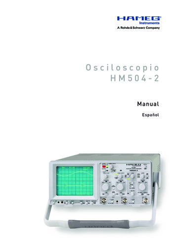
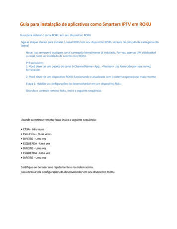
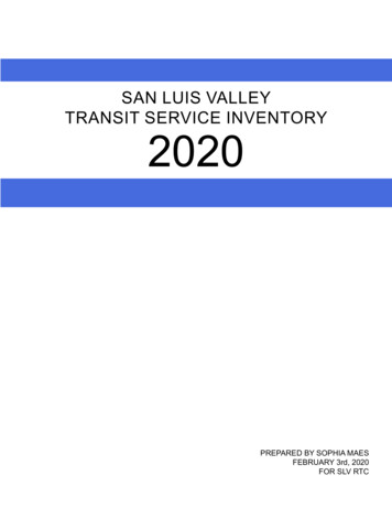
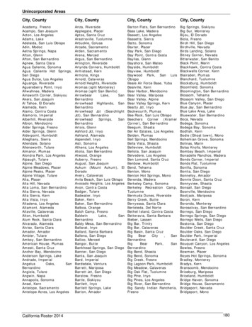
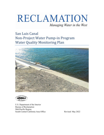
2) Confirm that non-project water entering the SLC is suitable for all downstreamusers;3) Provide reliable data for administration of the contracts and agreements; and4) Provide measurements of depth to groundwater to prevent subsidence.Study AreaThe Study Area (Figure 1) encompasses the SLC from the O’Neill Forebay (Check 13)to Kettleman City (Check 21), which is the federal portion of the California Aqueduct.Figure 2 depicts the wells in Westlands along the SLC.The study area also includes Westlands Lateral 7. For this program, Lateral 7 will betreated as one point of discharge. Water quality in Lateral 7 will be measured at theAdams Avenue pumping plant.3
Figure 1. Project vicinity map4
Figure 2. Location of Groundwater Wells within Westlands5
Water Quality Monitoring PlanAll non-project water must meet the standards listed in Tables 5 and 6 prior to enteringthe SLC. No dilution in the SLC will be allowed. Manifolded wells may discharge if theblend meets the standards listed in Tables 5 and 6.All water quality analyses must be conducted by a laboratory listed in Table 7. All watersamples must be sampled and preserved according to established protocols in correctcontainers. The costs of sampling and analysis of all non-project water will be borne bythe well operators.SamplingMendota Pool Group wells participating in this program are regulated by the MendotaPool Group Groundwater Pump-in Program Monitoring Plan (MPG Monitoring Plan).These wells must meet the requirements outlined in the MPG Monitoring Plan prior tointroduction into the Mendota Pool. To prevent redundant data collection, MendotaPool Group wells are exempt from Baseline and Routine Sampling of Individual wellsand Depth to Groundwater sampling as outlined in this document, this data is collectedunder the MPG Monitoring Plan. The cumulative effect of Mendota Pool water will bemeasured at Lateral 7.Baseline Sampling of Individual WellsTable 5 is a short list of constituents of concern to be measured in each well each yearbefore pumping into the SLC to screen out non-compliant wells2. There will be a onetime screening for the presence of Perfluorooctanoic acid (PFOA) andPerfluorooctanesulfonic acid (PFOS) and if detected, Reclamation and DWR will workwith Westlands on conducting additional sampling. Reference Table 5 for new PFOAand PFOS sampling. Wells that do not meet this short list may not participate in theprogram.Each well must be tested every three years for all constituents listed in Table 6 beforepumping in the SLC. Each report must clearly identify the location of each source ofnon-project water.Reclamation, in coordination with DWR and the State Water Contractors, may allowminor exceedances of certain secondary Title 22 constituents if all primary standards aremet.All new wells proposed to participate in the program must be approved by Reclamation prior todischarging any groundwater into the SLC or Lateral 7.2 Reclamationwill provide instructions for sampling groundwater.6
Routine Sampling of Individual WellsEach well must be tested weekly during the first four weeks of pumping for the short listof constituents (Table 5), then monthly while actively pumping into the SLC to confirmthat the water quality is consistent, predictable, and reliable.The short list may be modified, in consultation with DWR, to add constituents of concernor drop non-detected constituents.Reclamation will allow the introduction of water from two or more wells through onedischarge point if the blended water meets the Title 22 standards. Special monitoringmay be required for these situations.The following information must be submitted to Reclamation prior to pumpinggroundwater into the SLC:-the location of each well, pumping rate, and point of discharge into the SLC;-complete Title 22 water quality analyses for each well-the depth to groundwater in each well before pumping into the SLC commencesWhen the Project is operating, Westlands will provide DWR and Reclamation withweekly schedules which identify the flow from the active wells.Westlands will provide weekly updates identifying the current and anticipated waterquality changes within the SLC by using the daily model. The goal is to provideReclamation and the State Water Project Facilitation Group with a day-to-day predictionof downstream water quality using real-time pump-ins, real-time upstream backgroundflows, and current background water quality data.Lateral 7 SamplingNon-project water will only enter Lateral 7when water is being pumped into the SLC,not when flow is entering the Mendota Pool.Westlands must collect samples from Lateral 7 at the Adams Avenue pump station.Lateral 7 water must be tested for the full suite of Title 22 (Table 6) every year. Table 5constituents will be sampled weekly for the first four weeks, then monthly for theduration of pumping at the locations listed in Table 3. There will be a one-timescreening for the presence of Perfluorooctanoic acid (PFOA) andPerfluorooctanesulfonic acid (PFOS) from Lateral 7 at Adams Avenue pump station andif detected, Reclamation and DWR will work with Westlands on conducting additionalsampling. Reference Table 5 for new PFOA and PFOS sampling.Westlands must take weekly field measures for EC and turbidity at locations listed inTable 3.7
Depth to GroundwaterWell owners will measure the initial depth to groundwater in each well before pumpinginto the SLC, and monthly from October through December and every other monthoutside of that range while the Pump-in Program is in effect. Measurements must bemade using industry approved methods.An individual well will be shutoff when its Depth to Groundwater reaches 75% of thedifference between the Fall/Winter Median Groundwater Level and the Max DTGWusing the following equation:Shutoff Trigger 0.75*(Max DTGW-Fall/Winter Median) Fall/Winter MedianIf an individual well is shutoff due to groundwater levels reaching the shutoff trigger,it will not be allowed to resume pumping until it reaches 70% of the differencebetween the Fall/Winter Median Groundwater Level and the Max DTGW using thefollowing equation:Well Resumption 0.70* (Max DTGW-Fall/Winter Median) Fall/WinterMedianGroundwater level measurements will follow a strict schedule. If a well is shutoff itwill not be measured again until the next scheduled measurement date. Theparticipants must notify Reclamation in writing when a well is shutoff or resuming.See Definitions section for explanation for Max DTGW and Fall/Winter Median.Monitoring and ReportingSan Luis Canal MonitoringMean daily salinity and turbidity will be measured with the DWR sensors that report realtime data to CDEC (Table 1). Westlands will download daily average data for SLCChecks 13 and 21 to measure changes in the canal between these checks that may beattributable to the addition of the non-project water.Westlands will use a mass balance model to estimate the contribution of salinity to theSLC from the actively pumping wells and Lateral 7 and compare this with the real-timedata.If the addition of the non-project water is increasing the salinity of water in the SLC morethan 100 uS/cm between Check 13 and Check 21 (Table 4), Reclamation will work withWestlands and the well operators to turn off high salinity wells.The addition of non-project water must not raise the salinity in the SLC at Check 21above 700 uS/cm, equivalent to 450 mg/L Total Dissolved Solids (Table 4).The addition of non-project water must not raise the sodium in the SLC at Check 218
above 80 mg/L (Table 4). If the sodium concentration does exceed 80 mg/L,Westlands will shut off wells with the highest concentration of sodium until theconcentration at Check 21 is less than 80 mg/L, based on Westlands’ blendingmodel.If the salinity of water passing Check 13 is greater than 700 uS/cm, Reclamation andWestlands will coordinate with DWR to modify or restrict non-project pumping.If the addition of the non-project water from Lateral 7 is increasing the turbidity of waterin the SLC more than 10 NTU (Table 4), Reclamation will work with Westlands toreduce discharge from the lateral. Changes in turbidity are measured by collectingsamples upstream of and downstream of Lateral 7 (Table 3).Westlands will run model simulations, as needed, to quantify anticipated improvementsin conductivity with the termination of pumping from specific wells. The participatingwells with the highest salinity will be targeted first, continuing to the wells with thelowest concentrations until canal water quality stabilizes or improves. As salinity atCheck 21 improves, wells will be brought on-line to commence pumping.DWR collects monthly grab samples at Checks 13 (KA007089) and 21 (KA017226) tomeasure trace metals and other minerals in the canal water. The data will be posted here:San Luis Canal Check uality/station county/select station.cfm?URLStation KA007089&source mapSan Luis Canal Check uality/station county/select station.cfm?URLStation KA017226&source mapDWR and Westlands will review these results to identify water quality changes in theSLC and will determine if they are caused by the addition of the non-project water.Data Compilation and ReviewAll flow and water quality data collected by Westlands will be presented each month toReclamation and DWR via e-mail. Reclamation will review the data to identify changesin the quality of water in the SLC and in individual wells, and potential changes in thelocal aquifer that could lead to overdraft or subsidence. Reclamation, in consultation withDWR, will direct Westlands on the continuation of pumping of groundwater into theSLC.AccessParticipating well owners must allow Reclamation and DWR staff permission to accessthe wells, if requested.DWR Monitoring of Wells9
DWR may collect samples for water quality testing for any constituents of concern fromany Westlands source well or at any point of water entry into the Aqueduct for testing.DWR will use Bryte Chemical Laboratory or TestAmerica Labs for all DWR well sampleanalyses and the data will be available to Westlands for review. If any well tested byDWR is found to exceed the identified MCL’s, Reclamation will direct Westlands to stoppumping immediately. The discharge must not resume unless it is demonstrated thatadjustments have been made to the well or cluster of wells that allows it to dischargewater that meets the required objectives. Westlands will coordinate with well operators toprovide access for DWR personnel to conduct any of the following activities on privateproperty within Westlands’ service area during the term of this Proposal:-Verification of metering calibration standards and requirements for flow meterslocated at the point of entry into the Aqueduct and at the point of delivery out ofthe Aqueduct,-Collection of water samples from source wells and at the point of pump-in to theAqueduct for testing of water quality,-Any other activities deemed necessary by DWR to comply with the terms of thisProposal.RevisionReclamation reserves the right to modify this monitoring program at any time.Revised: May 4, 202210
Table 1. Real-Time Monitoring StationsLocationSan Luis CanalCheck 13O’Neill ForebaySan Luis CanalCheck 21Kettleman vity,turbidityFrequencyRemarksCDEC Site: C13Real-timeCDEC Site: C21Key: CDEC: California Data Exchange CenterDWR: California Department of Water ResourcesTable 2. Routine San Luis Canal Water Quality Monitoring StationsLocationSan Luis CanalCheck 13O’Neill ForebaySan Luis CanalCheck 21Kettleman CityAgencyDWRParametersMinerals,trace metals,nutrients,pesticidesFrequencyRemarksGrab sampleMonthlyGrab sampleSource: DWR Water Data LibraryTable 3. Routine Monitoring of WWD Lateral 7LocationSan Luis CanalMilepost 113.82Lincoln Ave(upstream site)AgencyParametersWestlandsEC, turbidityshort listWestlands Lateral 7at Adams AvenueWestlandsSan Luis CanalMilepost 117.47Manning Ave(downstream site)WestlandsEC, turbidityshort listEC, turbidityshort listFrequencyWeeklyWeekly x 4,Monthly3WeeklyWeekly x 4,Monthly3WeeklyWeekly x 4,Monthly3RemarksField measurementsgrab sampleField measurementsgrab sampleField measurementsgrab sample3 This water will also be tested for the short list of constituents weekly for the four weeks and monthly for the durationwhile water is being pumped into the canal.11
Table 4. Maximum allowable changes in the San Luis Canal caused by the addition ofnon-project groundwaterConstituentMonitoring LocationElectrical conductivityBetween San Luis CanalChecks 13 and 21TurbidityBetween the Lateral 7upstream site anddownstream siteElectrical conductivityTotal dissolved solidsConcentration ofseleniumConcentration ofsodiumConcentration of anyTitle 22 constituentIn the San Luis Canal atCheck 21Maximum concentration inthe San Luis CanalLess than 100 uS/cmincrease between thechecksLess than 10 NTUNot to exceed 700 uS/cmNot to exceed 450 mg/LNot to exceed 2 ug/LNot to exceed 80 mg/LLess than half of a Title 22MCLIf the maximum concentrations are exceeded in the canal, Reclamation will direct theDistrict to reduce or terminate pumping of non-project water into the San Luis Canal.The District may provide a forecast from its water balance model to identify which wellsto reduce or terminate, and whether to reduce or terminate pumping form Lateral 7.12
San Luis CanalNon-Project Water Pump-in ProgramWater Quality Monitoring PlanTable 5. Water Quality Standards, Short , totalHexavalent chromiumManganeseNitrate (as NO3)SeleniumSodiumSpecific ConductanceSulfateTotal Dissolved SolidsTotal Organic CarbonGross MaximumContaminant Level0.0102.0(1)Detection Limit forReporting0.002(2)CAS lyticalMethodEPA 200.8EPA )30.000005(3)(5)96-18-4EPA 300.1EPA 200.7EPA 200.8EPA 200.7EPA 300.1EPA 200.8EPA 200.7SM 2510BEPA 300.1SM 2540CEPA 415.3SM 7110CSRL 524M13
One-Time ScreeningPerfluorooctanic acid (PFOA)**Perfluorooctanesulfonic acid (PFOS)**ng/Lng/LN/AN/A0.822.7(15)(15)EPA 537.1EPA 537.1Short list to be measured before pumping occurs, then weekly for four consecutive weeks, and monthly for the duration of pumping into the San Luis Canal.*Monthly testing only**One-time screening conducted prior to pumping individual wells and from Lateral 7 at the Adams Avenue pump station. Although there are no MCLsdeveloped yet, there are notification levels and response levels. The notification levels are 5.1 PPT (PFOA) and 6.5 PPT (PFOS). The response levels are 10 PPT(PFOA) and 40 PPT (PFOS) based on a running four quarter average. The lowest concentration minimum reporting levels (LCMRL) are 0.82 ng/L (PFOA) and 2.7ng/L (PFOS).Revised: 26 August 202114
San Luis CanalNon-Project Water Pump-in ProgramWater Quality Monitoring PlanTable 6. Title 22 Water Quality AsbestosBariumBerylliumCadmiumChromium, totalCopperCyanideFluorideHexavalent ChromiumLeadMercuryNickelNitrate (as NO3)Nitrate Nitrite (sum as g/Lmg/Lmg/Lmg/Lmg/Lmg/Lmg/Lmg/LMaximumContaminant )(9)(1)(1)(1)(1)Detection Limit forReporting0.050.0060.0020.2 MFL 2)CAS 727-37-914797-55-8RecommendedAnalytical MethodEPA 200.7EPA 200.8EPA 200.8EPA 100.2EPA 200.7EPA 200.7EPA 200.7EPA 200.7EPA 200.7EPA 335.2EPA 300.1EPA 218.7EPA 200.8EPA 245.1EPA 200.7EPA 300.1EPA 353.215
Nitrite (as -28-028249-77-6EPA 300.1EPA 314/331/332EPA 200.8EPA 200.8EPA orCopperIronManganeseMethyl-tert-butyl ether (MTBE)Odor -thresholdSilverSpecific ConductanceSulfateThiobencarbTotal Dissolved SolidsTurbidityZinc(6)7440-66-6EPA 200.7EPA 300.1EPA 110EPA 200.7EPA 200.7EPA 200.7EPA 502.2/524.2SM 2150BEPA 200.7SM 2510 BEPA 300.1EPA 527SM 2540 CEPA 190.1/SM2130BEPA 200.7(13)7440-42-87439-98-77440-23-5EPA 200.7EPA 200.7EPA 828249-77-6(7)(6)Other Required AnalysesBoronMolybdenumSodium(11)(12)16
RadioactivityGross AlphapCi/LOrganic Chemicals(a) Volatile Organic Chemicals (VOCs)Benzenemg/LCarbon mg/LEthylbenzenemg/LMethyl-tert-butyl etrachloroethanemg/LTetrachloroethylene hloroethylene (TCE)mg/LTrichlorofluoromethanemg/LSM 108-88-3120-82-171-55-679-00-579-01-675-69-4EPA 502.2/524.2EPA 502.2/524.2EPA 502.2/524.2EPA 502.2/524.2EPA 502.2/524.2EPA 502.2/524.2EPA 502.2/524.2EPA 502.2/524.2EPA 502.2/524.2EPA 502.2/524.2EPA 502.2/524.2EPA 502.2/524.2EPA 502.2/524.2EPA 502.2/524.2EPA 502.2/524.2EPA 502.2/524.2EPA 502.2/524.2EPA 502.2/524.2EPA 502.2/524.2EPA 502.2/524.2EPA 502.2/524.2EPA 502.2/524.2EPA 502.2/524.2EPA 502.2/524.217
1,1,2-Trichloro-1,2,2-Trifluoroethanemg/LVinyl Chloridemg/LXylenesmg/L(b) Non-Volatile Synthetic Organic Chemicals quatmg/Lmg/LEndothallEndrinmg/LEthylene Dibromidemg/LGlyphosate (Roundup)mg/LHeptachlormg/LHeptachlor tadienemg/LLindane 3-175-01-41330-20-7SM 6200BEPA 502.2/524.2EPA 4-81024-57-3118-74-177-47-458-89-972-43-5EPA 505/507/508EPA 505/507/508EPA 515.1EPA 525.2EPA 531.1EPA 505/508EPA 515.1EPA 515.1EPA 502.2/504.1EPA 506EPA 506EPA 5151-4EPA 549.2EPA 548.1EPA 505/508EPA 502.2/504.1EPA 547EPA 508EPA 508EPA 505/508EPA 505/508EPA 505/508EPA 505/5082212-67-123135-22-087-86-5EPA 525.1EPA 531.1EPA 515.1-318
PicloramPolychlorinated BiphenylsSimazineThiobencarb D (Dioxin)2,4,5-TP (Silvex)mg/Lmg/Lmg/Lmg/Lmg/Lmg/Lmg/Lmg/LOther Organic mended Analytical Methods:Maximum Contaminant Levels:0.50.00050.0040.070.0030.0000053 x 10-80.050.0150.10(4)(4)(4)
quality changes within the SLC by using the daily model. The goal is to provide Reclamation and the State Water Project Facilitation Group with a day-to-day prediction of downstream water quality using real-time pump-ins, real-time upstream background flows, and current background water quality data. Lateral 7 Sampling