Transcription
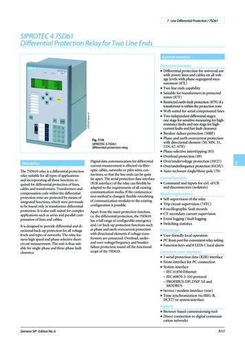
Generator G1 Relay ProtectionDescription of OperationBy Chris Werstiuk, Valence Electrical Training Services1. IntroductionThis document has been created to explain the protection settings and application for the 120MWgenerator [G1] installed at the Dennison Power Station. The generator has the following nameplatedata: Valence Electrical Training Services9888 West Belleview Ave., PMB #122, Littleton CO 50-8257Page 1 of 78
Generator G1 Relay ProtectionDescription of OperationTable of ContentsGenerator G1 Relay Protection . 1Description of Operation. 11. Introduction. 1Table of Contents . 22. Manufacturer’s Specifications . 53. Power System Specifications . 8A. Generator Relays . 8B. Instrument Transformers . 8C. Generator Step-Up Transformer . 9D. Power System. 94.5.General Relay Principles . 10Global Settings. 11A. M-3425A Settings . 11a)b)c)d)M-3425A System Settings - Setup System Menu . 11M-3425A I/O Setup - Setup System Menu . 12M-3425A Output Seal-In Time - Setup System Menu. 12Set Date & Time . 12B. SEL-300G Settings . 13a) SEL-300G Global Settings (SET G) . 13b) SEL-300G Group 1 Settings (SET). 13c) Set Date & Time . 156.Protection Settings . 16A. Phase Distance (21) Protection . 16a)b)c)d)e)21#1 Phase Distance Settings . 1621#2 Phase Distance Settings . 17M-3425A 21: Phase Distance #1 Setpoints . 18M-3425A 21: Phase Distance #2 Setpoints . 18SEL-300G 21 Mho Element Settings . 19B. Volts/Hertz (24) Protection . 20a)b)c)d)e)f)g)24-Alarm Settings . 20M-3425 24: Volts/Hertz Overexcitation Definite Time #1 Settings . 21SEL-300G 24 Element Settings - Level 1 . 2124-Trip Settings . 22M-3425 24: Volts/Hertz Overexcitation Inverse Time Settings. 23M-3425 24: Volts/Hertz Overexcitation Definite Time #2 Settings . 24SEL-300G 24 Element Settings - Level 2 . 24C. Phase Undervoltage (27) Protection . 26a)b)c)d)M-3425A 27#1 Phase Undervoltage Settings . 27M-3425A 27#2 Phase Undervoltage Settings . 27SEL-300G 27 Element Settings - 27PP1 . 28SEL-300G 27 Element Settings - 27PP2 . 29 Valence Electrical Training Services9888 West Belleview Ave., PMB #122, Littleton CO 50-8257Page 2 of 78
Generator G1 Relay ProtectionDescription of OperationD. 100% Stator Earth (27TH, 27TN, or 64G2) Protection Settings . 30a) M-3425A 27TN#1 Third Harmonic Undervoltage, Neutral Settings. 32b) SEL-300G 64G Element Settings – 64G2. 33E. Reverse Power (32) Protection . 34a) M-3425A 32#1 Directional Power Settings . 34b) SEL-300G 32 Element Settings . 35F. Loss-of-Field (40) Protection . 36a) M-3425A 40#1: Loss-of-field Settings . 38b) M-3425A 40#2: Loss-of-field Settings . 39c) SEL-300G 40 Element Settings . 40G. Unbalance Overcurrent (46) Settings . 41a)b)c)d)e)f)46-Alarm Settings . 41M-3425 46: Negative Sequence Overcurrent Definite Time Settings. 41SEL-300G 46 Element Level 1 Settings . 4146-Trip Settings . 42M-3425 46: Negative Sequence Overcurrent Inverse Time Settings . 42SEL-300G 46 Element Level 2 Settings . 43H. Breaker-failure (50BF) Protection . 44a) M-3425A 50BF: Breaker-failure Settings . 44b) SEL-300G 50BF Breaker-failure Settings . 45I. Inadvertent-Energization (50/27) Protection. 46a) M-3425A 50/27: Inadvertent Energizing Settings . 47b) SEL-300G Inadvertent Energizing Settings . 47J. Phase Undervoltage (59) Protection . 49a)b)c)d)M-3425A 59#1 Phase Undervoltage Settings . 50M-3425A 59#2 Phase Undervoltage Settings . 50SEL-300G 59 Element Settings - 59PP1 . 51SEL-300G 59 Element Settings - 59PP2 . 52K. Neutral Overvoltage (59N or 64G1) Protection Settings . 53a) M-3425A 59N: Neutral Overvoltage Settings . 54b) SEL-300G 64G Element Settings – 64G1. 54L. Loss-of-Potential (60, 60FL, 60LOP) Settings . 55a) M-3425 60FL: VT Fuse Loss Detection Settings . 55b) SEL-300G 60-Alarm Settings . 56M.Out-Of-Step / Loss-Of-Synchronism (78) Protection Settings . 57a) M-3425A 78: Out of Step Settings. 59b) SEL-300G 78 Element Settings . 60N. Under/Over Frequency (81) Protection. 61a)b)c)d)e)M-3425A Under/Over Frequency Settings - 81#1 . 62M-3425A Under/Over Frequency Settings - 81#2 . 62M-3425A Under/Over Frequency Settings - 81#3 . 62M-3425A Under/Over Frequency Settings - 81#4 . 63SEL-300G 81 Element Settings . 63O. Phase Differential (87) Protection Settings . 65a) M-3425A 87: Phase Differential Current Settings . 65b) SEL-300G 87 Element Settings . 66 Valence Electrical Training Services9888 West Belleview Ave., PMB #122, Littleton CO 50-8257Page 3 of 78
Generator G1 Relay ProtectionDescription of Operation7.Display Settings . 678.Event Recording Settings . 70A. SEL-300G Global Settings. 67A. M-3425A Settings . 70a) Relay / Sequence of Events Recorder Settings . 70b) Relay / Setup Oscillograph Recorder Settings . 70B. SEL-300G Settings . 71a) SEL-300G Global Settings. 71b) SEL-300G Report Settings. 71c) SEL-300G Group 1 Settings . 729.Control and Logic Settings . 75A. M-3425A Settings . 75B. SEL-300G Settings . 75a) SEL-300G Global Settings. 76c) SEL-300G Group 1 Settings . 76 Valence Electrical Training Services9888 West Belleview Ave., PMB #122, Littleton CO 50-8257Page 4 of 78
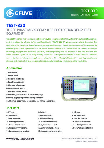
Generator G1 Relay ProtectionDescription of Operation2. Manufacturer’s SpecificationsThe manufacturer provided the following specifications regarding the generator’s capabilities:DescriptionsRated @ 40.0 CCurve A @ 15.0 CCurve B @ 10.0 C133.3120.00.85 / 605.57813.840.0160.0144.10.85 / 606.69413.815.0‐5.0 / 5.0StationaryANSI /IECB165.3148.80.85 / 606.91713.810.0Apparent Power (MVA)Active Power (MW)Power Factor / FrequencyStator Current (kA)Rated Voltage (kV)Cold Air TemperatureVoltage Range (%)Type of ExcitationStandardInsulation Class BStator WindingType of CoolingCooling MediumHeat Loss Dissipated at Rated LoadIndirectAir222.4 kWStator CoreType of CoolingCooling MediumHeat Loss Dissipated at Rated LoadRadialAir237.0 kWRotor WindingType of CoolingCooling MediumHeat Loss Dissipated at Rated LoadStator Winging – Slot Temperature RiseRotor Winding – Average Temperature riseDirect RadialAir287.7 kW62.8 K71.1 K Valence Electrical Training Services9888 West Belleview Ave., PMB #122, Littleton CO 50-8257Page 5 of 78
Generator G1 Relay ProtectionDescription of OperationEfficienciesDescriptionsOutput (MVA)Power FactorCold Gas Temperature ( C)Stationary – 100% LoadStationary – 75% LoadStationary – 50% LoadStationary – 25% LoadRated AtCurve ACurve 98.15%96.94%Output and Allowable Load UnbalanceContinuous Load Unbalance – Permissible I2Short Time (K I22t)Output at Deviating Cold Air TemperatureOutput Limit with 1 Cooler Section Out of ServiceOutput at CosΘ 0 – Under‐Excited (MVAR)Output at CosΘ 0 – Over‐Excited (MVAR)Output at CosΘ 0 – Over‐Excited – Curve A (15 C) (MVAR)Output at CosΘ 0 – Over‐Excited – Curve B (10 C) (MVAR)10%30ΔT 0.8% / K67%58.591.3109.691.3Generator – Exciter Currents and VoltagesGenerator LoadNo Load125% Load100% Load75% Load50% Load25% LoadRated @ 40.0 CCurrentField(A)Voltage (V)2981011822662519395142480391314247188Curve A @ 15.0 CCurrentField(A)Voltage (V)‐‐970‐‐‐‐‐459‐‐‐Curve B @ 10.0 CCurrentField(A)Voltage (V)‐‐1003‐‐‐ Valence Electrical Training Services9888 West Belleview Ave., PMB #122, Littleton CO 50-8257‐‐476‐‐‐Page 6 of 78
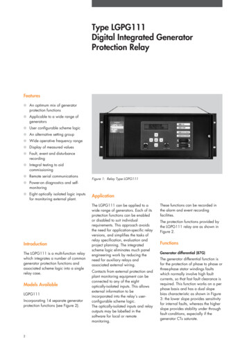
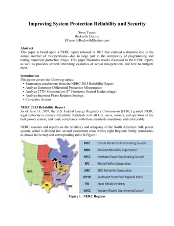
Generator G1 Relay ProtectionDescription of OperationReactances Base MVA 125MVAD‐Axis Sub‐TransientD‐Axis TransientD‐Axis SynchronousQ‐Axis Sub‐TransientQ‐Axis TransientQ‐Axis SynchronousNegative Phase SequenceZero Phase SequencePotierStator LeakageNo Load Short Circuit Ratio SAT.XD'' UNSATXD' UNSATXD UNSATXQ'' UNSATXQ' UNSATXQ UNSATX2 10.9%26.8%15.1%XD'' SATXD' SAT‐XQ'' SATXQ' SAT‐X2 ��0.57Time ConstantsD‐Axis Sub‐TransientD‐Axis TransientQ‐Axis Sub‐TransientQ‐Axis TransientDC Time ConstraintTD'' Short CircuitTD' Short CircuitTQ'' Short CircuitTQ' Short CircuitTA0.031s0.873s0.068s0.534s0.030sTDO'' No‐LoadTDO' No‐LoadTQO'' No‐LoadTQO' No‐Load0.045s7.150s0.150s2.500sResistancesOf Stator Windings @ 20 COf Rotor Windings @ 20 CPositive‐sequenceInverse SequenceNull 201%0.267%Reactive Capability Curve Valence Electrical Training Services9888 West Belleview Ave., PMB #122, Littleton CO 50-8257Page 7 of 78
Generator G1 Relay ProtectionDescription of Operation3. Power System SpecificationsA.Generator RelaysTwo generator protection relays from two different manufacturers have been chosen to provideredundant protection for the generator. The generator relay details are:Beckwith Electric Company M‐3425AModel Number M‐3425A#8736Frequency 60HzOutput Contacts 23Input Contacts 14Aux 125VDCCom 2 EthernetRated Voltage Inputs 60 – 140 VACRated Current Inputs 5A, NomPower Supply 1 85 – 165VAC/DCPower Supply 2 85 – 165VAC/DCB.Schweitzer Engineering LaboratoriesSEL‐300GModel Number 0300G30H425XX4XOutput Contacts 7Input Contacts 6Logic Input Voltage 125VDCRated Current Inputs 5A, NomPower Supply 1 125/250VDCInstrument TransformersThe generator is connected to the power system via the following instrument transformers: G1-PT Two Delta-connected PTs with a 120:1 ratio [14400:120V] connected to thegenerator terminals. G1-CTN Three Wye-connected C800 CTs installed around the generator neutralconductors with a 1600:1 ratio [8000:5A]. G1-NPT One single-phase power transformer connected between the generator neutral starpoint and ground to provide a high-impedance ground connection. The PT ratio is 31.75[7620:240V] with a secondary resistor connected across its secondary terminals. 52-G1-CT Three Wye-connected C800 CTs installed around the generator circuit breakerphase conductors with a 1600:1 ratio [8000:5A]. Valence Electrical Training Services9888 West Belleview Ave., PMB #122, Littleton CO 50-8257Page 8 of 78
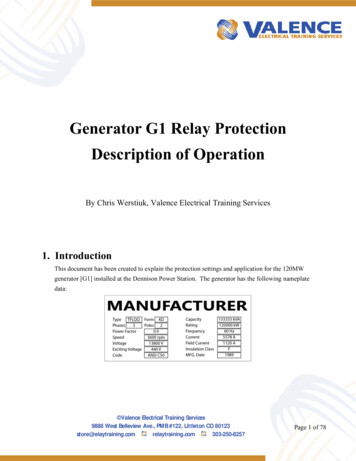
Generator G1 Relay ProtectionDescription of OperationC.Generator Step-Up TransformerThe generator is connected to a Generator Step-Up Transformer [GSU] with the followingspecifications: Designation GSU1Type ONAN/ONAF/ONAFMVA 130 / 175 / 215 MVAPrimary Volts 148,600 VSecondary Volts 13,800 VNumber of Taps 5Impedance [Tap3] 12.29 %ZaAc Connection Type: Yd1CBbTherefore, the transformer impedances are:The transformer impedance in ohms at 13.8kVis:Z(Ω) The transformer impedance measured bythe relay in ohms is:kVBASE2 Z%100 MVABASE13.82 12.29Z(Ω) 100 130Z CT RatioZSEC (Ω) PRIPT RatioZSEC (Ω) Z(Ω) 0.18 D.0.18 1600120ZSEC (Ω) 2.40 Power SystemA power system model was created, and the positive-sequence power system impedance wascalculated to be 0.15225Ω @ 80.00 . The power system impedance measured by the relay willbe:Z CT RatioZSEC (Ω) PRIPT RatioZSEC (Ω) 0.15225 @80.00 1600120Z(Ω) 2.03 @80.00 Valence Electrical Training Services9888 West Belleview Ave., PMB #122, Littleton CO 50-8257Page 9 of 78
Generator G1 Relay ProtectionDescription of Operation4. General Relay PrinciplesThe generator protection provided by these relays fall into the following categories: Some of the elements inside the relay [21, 24, 27, 32, 40, 46, 50/27, 59, 78, and 81] are set todetect problems with the generator or power system that can potentially harm the generator,but the protective element will operate before generator damage can occur. Any of these tripsshould open the generator circuit breaker to isolate the generator from the power system, butthe generator should remain energized, which will allow the operators to re-synchronize thegenerator after the problem has been corrected. The operators will also receive a normallyopen (NO) trip signal through the SCADA system so they can evaluate the situation andrespond accordingly. The following elements inside the relays [27TN, 59N, and 87] indicate a possible probleminside the generator. These elements will trip a generator lockout relay that will:o open the generator circuit breaker,o open the generator’s excitation circuit breaker,o send a shutdown signal to the generator’s prime mover, ando send a normally-open trip signal to the operators via a SCADA system. A breaker-failure scheme [50BF] will start timing when any of the internal relay tripelements operate when the circuit breaker is closed. The circuit breaker will be consideredclosed if the 52b contact connected to the relay opens, OR any measured phase currentthrough the circuit breaker is greater than 0.50 secondary amps. The breaker-failure schemewill seal itself in when any trip is received. If the circuit breaker does not open [52b contactcloses or all phase currents drop below 0.50 secondary amps] within 0.17 seconds after thetrip signal is detected, the relay will operate an 86BF-Lockout relay, which will trip allcircuit breakers directly connected to the generator circuit breaker to isolate the generatorfrom the rest of the power system. The breaker-failure scheme will disarm itself if thegenerator circuit breaker opens within 0.17s after a trip signal is detected. The relay will send a normally-closed [NC] alarm signal to the SCADA system if an overexcitation [24], unbalance overcurrent [46], or fuse problem [60] is detected. All aspects of the enabled protective elements and control functions should be recorded inthe relay’s sequence of event report to assist maintenance and troubleshooting personnel. All protective elements should have clear targets or messages on the front panel of the relayto help operators determine what caused a generator trip. All settings are based on the generator manufacturer’s supplied data, IEEE recommendationsin IEEE Guide for AC Generator Protection, IEEE Std C37.102 -2006(R2012), andNERC requirements for the Western Interconnection in Standard PRC-024-2 — GeneratorFrequency and Voltage Protective Relay Settings. Valence Electrical Training Services9888 West Belleview Ave., PMB #122, Littleton CO 50-8257Page 10 of 78
Generator G1 Relay ProtectionDescription of Operation5. Global SettingsThe following general settings should be applied to the protection relays to ensure they adequatelyprotects the generator and power system:A. M-3425A Settingsa) M-3425A System Settings - Setup System MenuThe following settings should be applied to ensure the relay properly interprets the signalsfrom the power system: The “Nominal Voltage” sets the nominal generator voltage [13,800V] through the PTs[120:1], which should be 115.0V [13,800V / 120] phase-phase [P-P] secondary voltsbecause the PTs are Delta connected. The “Nominal Current” sets the nominal generator current [5,578A] through the CTs[1,600:1], which should be 3.49A [5,578A / 1600] secondary amps. The “Phase Rotation” of the generator and power system is ABC, as shown on the singleline and three-line drawings. The “59/27 Magnitude Select” setting should be RMS to ensure maximum meteringinside the relay, which will add additional time delays for some non-time sensitiveelements. The “50DT Split Phase Diff” setting is disabled because no split phase conductors areavailable to monitor. The “Delta-Y Transform” setting should be Delta-AC to match the transformernameplate’s phase shift specification [Yd1] and nameplate images:aAcCBb The “V.T. Configuration” setting should be “Line to Line” to reflect the Delta-connectedPTs. The “V.T. Phase Ratio” should be 120.0 to match the 14,400:120V PTs connected to therelay. The “V.T. Neutral Ratio” should be 31.8 to match the 7,620:240V neutral groundingtransformer connected to the relay. The actual ratio [31.75:1] has been rounded up to31.8V because the relay only allows one decimal point. The “V.T. VX Ratio” is 1.0 because there is nothing connected to the VX terminals andthis setting cannot be disabled. Valence Electrical Training Services9888 West Belleview Ave., PMB #122, Littleton CO 50-8257Page 11 of 78
Generator G1 Relay ProtectionDescription of Operation The “C.T. Phase Ratio” should be 1600 to match the 8000:5 CTs connected to the IA, IB,and IC terminals on the relay, which should be the CTs installed on the generator circuitbreaker. The “C.T. Neutral Ratio” should be 1600 to match the 8000:5 CTs connected to the Ia,Ib, and Ic terminals on the relay, which should be the CTs installed around the generatorneutral conductors.b) M-3425A I/O Setup - Setup System MenuThe following settings should be applied to ensure the relay properly interprets the inputand output signals from the power system: All of the “Input Active State” input settings should be “Close” to match normalfunctionality. All of the “Latched Outputs” settings should be blank because none of the output relayson the relay should latch. All of the “Pulsed Outputs” settings should be blank because this application does not usepulsed outputs.c) M-3425A Output Seal-In Time - Setup System MenuAll of the “Relay Output Seal-In Time (Cycles)” settings should be set to 15 cycles, whichmeans that all outputs should stay closed at least 15 cycles after the element that caused thetrip resets. Relay output contacts can be damaged when they open while under load, andthis setting is applied to allow external devices to open the 125VDC control circuit beforethe relay contact can open.d) Set Date & TimeThe relay tester should make sure the M-3425A clock is turned on and set at the correctdate and time to ensure all event records are properly recorded and can be compared toother recording devices during troubleshooting tasks. Valence Electrical Training Services9888 West Belleview Ave., PMB #122, Littleton CO 50-8257Page 12 of 78
Generator G1 Relay ProtectionDescription of OperationB.SEL-300G Settingsa) SEL-300G Global Settings (SET G) The FNOM (Nominal Frequency) setting should be “60” Hz to match the nominalgenerator and power system frequency. The PHROT (Phase Rotation) setting should be “ABC” to match the phase rotation of thegenerator and power system, as shown on the single-line and three-line drawings. The DELTA Y (Phase Potential Connection) setting should be “D” to reflect the Deltaconnected PTs. The TGR (Group Change Delay) can be any value because the group settings inside therelay are disabled. The SS1 (Group 1 Select Input) setting should be “1” to ensure that the relay always staysin Group 1 because only Group 1 settings have been set to protect the generator. The SS2 (Group 2 Select Input) setting should be “0” to ensure that the Group 2 settingsare never applied because they are set to default settings and will not protect thegenerator correctly. All IN#0#D (Input Debounce time) settings should be “0.5” cycles to ensure that an inputhas been closed for at least 0.5 cycles before it will be considered ON in the relay’s logic.These settings will prevent nuisance operations caused by chattering contacts.b) SEL-300G Group 1 Settings (SET) The RID (Relay Identifier) setting should be “G1 SEL-300G” to match the lamacoidabove the relay, the designation for this relay on all drawings, and the designation of allof this relay’s coordination curves in the coordination and arc flash study. The ID (Terminal Identifier) setting should be “DENNISON SUBSTATION” to matchthe substation the relay is installed in. All drawing should reflect this location. The CTR (Phase (IA,IB,IC) CT Ratio) setting should be “1600” to match the
Generator G1 Relay Protection Description of Operation By Chris Werstiuk, Valence Electrical Training Services 1. Introduction This document has been created to explain the protection settings and application for the 120MW generator [G1] installed at the Dennison Power Station. The generator has the following nameplate data: