Transcription
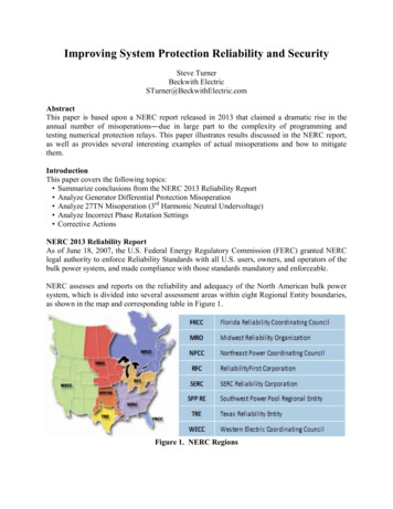
Improving System Protection Reliability and SecuritySteve TurnerBeckwith ElectricSTurner@BeckwithElectric.comAbstractThis paper is based upon a NERC report released in 2013 that claimed a dramatic rise in theannual number of misoperations―due in large part to the complexity of programming andtesting numerical protection relays. This paper illustrates results discussed in the NERC report,as well as provides several interesting examples of actual misoperations and how to mitigatethem.IntroductionThis paper covers the following topics: Summarize conclusions from the NERC 2013 Reliability Report Analyze Generator Differential Protection Misoperation Analyze 27TN Misoperation (3rd Harmonic Neutral Undervoltage) Analyze Incorrect Phase Rotation Settings Corrective ActionsNERC 2013 Reliability ReportAs of June 18, 2007, the U.S. Federal Energy Regulatory Commission (FERC) granted NERClegal authority to enforce Reliability Standards with all U.S. users, owners, and operators of thebulk power system, and made compliance with those standards mandatory and enforceable.NERC assesses and reports on the reliability and adequacy of the North American bulk powersystem, which is divided into several assessment areas within eight Regional Entity boundaries,as shown in the map and corresponding table in Figure 1.Figure 1. NERC Regions
The users, owners, and operators of the bulk power system within these areas account forvirtually all the electricity supplied in the United States, Canada, and a portion of Baja CaliforniaNorte, México. NERC released an official report in May of 2013 that featured statistics forprotection misoperations across the entire country.Major disturbances that occurred are ranked using a Daily Severity Risk Index. These include thefollowing blackouts: 1989 Quebec Solar Flare 1996 Western Disturbance 2003 Eastern Interconnection BlackoutMisoperations primarily resulted due to the following reasons as shown in Figure 2: Incorrect settings/logic/design errors Communication failure Relay failure or malfunctionThese events include Human Error during testing and maintenance activities. Human Errorduring testing and maintenance resulting in protection system activation has contributed to largedisturbance events.Figure 2. NERC 2012 Misoperation TableMost of these misoperations contribute to increasing Security Risk Index (SRI) and indicate thatthe number of transmission element outages is increasing.Corrective ActionsApplications requiring coordination of functionally different relay elements should be avoided.This type of coordination is virtually always problematic and is the cause of numerousmisoperations reported in the study period. For example, do not coordinate an overcurrentelement with a distance element; while the distance element has a fixed reach, the effective reachof the overcurrent element is dependent upon the strength of the source.
Misoperations due to setting errors can be reduced using the following techniques: Peer reviews Increased training More extensive fault studies Standard setting templates for standard schemes Periodic review of existing settings when there is a change in system topographyRemember that the greater the complexity of the protection scheme, the greater risk ofmisoperation. Simplicity is elegance.Misoperation Analysis87 Generator Phase Differential ProtectionThe customer reported a questionable generator protection relay trip. There are two mainprotection relays provided by different manufacturers but only one operated.Review of the relay settings revealed the relay that did not trip had a higher pickup setting by afactor greater than four times. The CTs have a knee point of 100 volts or less which is low andthere was the presence of heavy dc offset in the C-Phase current (Figure 3).Figure 3. C Phase Neutral Side CT Excitation CharacteristicFigures 4A and 4B show the high levels of dc offset present in C-Phase current during the event.DC offset current is the number one cause of CT saturation.
Figure 4A. Generator C-Phase CurrentFigure 4B. Generator C-Phase Differential CurrentHere is the minimum pickup for the relay that did not operate:Tap·O87P (4.4 amps)·(0.3) 1.32 ampsAs shown in Figure 5, the customer copied the settings from an arbitrary example in themanufacturer relay instruction book. The relay that tripped was more than four times as sensitive.
Figure 5. Nominal Current CalculationsThe blue triangle in Figure 6 corresponds to the C-Phase operating point which was just on theboundary of operation. The misoperation occurred when the current was coming out ofsaturation.Figure 6. 87 Phase Differential Operating CharacteristicThe DC offset present in fault current exponentially decays as shown in Figure 7. The digitalFourier transform algorithm cannot fully reject it.
Figure 7. DC Offset CurrentBest Practice: If the DC offset from transformer inrush (e.g., black start) or fault condition cancause CT saturation, then the following are appropriate for generator phase differentialprotection settings: Minimum pickup up to 0.5 amps secondary Slope of 20 percent Time delay up to 5 – 8 cyclesDetailed calculations are necessary for generator differential protection to determine if CTs cansaturate; do not simply copy settings from the relay instruction book without actual verification.Higher C class CTs can help to mitigate saturation (Figure 8).Figure 8. CT Saturation CalculationVCTMAX 2 (RCT 2 Rlead Rburden)The factor of 2 accounts for a fully offset current waveform which is worse case.
27TN Third Harmonic Neutral UndervoltageA utility experienced several misoperations when system voltage was low. However, the tripshown in Figure 9 occurred when the machine was under excited and drawing vars from system.Figure 9. Machine Real and Reactive Power at time of 27TN TripThe machine nominal power is 746.5 watts secondary.Conventional protection (59N) cannot detect grounds in last 5 to 10 percent of stator winding.27TN is not always reliable and may have to be blocked during specific operating conditions. Iffailure occurs in lower voltage portion of winding near neutral, a generator trip will not typicallyoccur until some other relay protection detects there is a problem, (e.g., arcing becomes sowidespread that other portions of winding become involved). 27TN sees stator ground faults veryclose to the machine neutral as shown in Figure 10.
Figure 10. 27TN and 59N Zones of Stator Ground Fault ProtectionThird harmonic neutral voltage changes as a function of load. The pickup setting is typically setequal to one-half of the minimum value measured during normal operation. Figure 11 illustrateshow complex it can be to securely set 27TN protection by use of the blocking functions.Figure 11. 27TN SettingsThe solution for this particular machine is to block on low forward power as this is the prevailingsystem condition when the nuisance trip occurs. The main drawback to this solution is there is noprotection for stator ground faults close to neutral during this operating condition.Best Practice: The customer was urged to considering installation of 100 percent stator groundfault protection using sub-harmonic voltage injection (64S) which they did (Figure 12).
20 HzGenerator20 HzBand oundingTransformer1A1SupplyVoltageDC age20 Hz CT64S RelayLowVoltage4445525359NVNINFigure 12. 64S Protection Connection DiagramThere has been recent experience with four such failures in large generators that demonstratelack of proper protection can be disastrous. Each of four failures caused massive damage togenerator and collectively had total cost, including repair and loss of generation, close to 500,000,000. This demonstrates that the failure of stator windings in the last five percent of thewinding is not uncommon. See Figures 13A, 13B and 13C.Figure 13A. Winding Damage - Broken Stator Winding Conductor
Figure 13B. Core and Winding Damage - Burned Open Bar in a SlotFigure 13C. Burned Away Copper - Fractured Connection Ring64S provides all of the following advantages: Detect stator ground when winding insulation first starts to break down and trip unitbefore catastrophic damage occurs. Trip in order of cycles since 20 Hz signal is decoupled from 60 Hz power system. Detect grounds close to machine neutral or even right at neutral thus providing 100percent coverage of stator windings. Detect grounds when machine is starting up or offline. Reliably operate with generator in various operating modes (such as a synchronouscondenser) and at all levels of real and reactive power output. 64S can be commissioned in less than one hour assuming there are no wiring errors. SeeFigure 14.Figure 14. Numerical Generator Relay 20 Hz Metering
Incorrect Phase Rotation SettingsNumerical protection relays require a setting to determine the correct phase rotation. Figure 15illustrates ABC phase rotation; however, some power systems are ACB.Figure 15. ABC Phase RotationTwo customers experienced generator protection misoperations due to incorrect phase rotationsettings. The first misoperation was 40 loss-of-field protection (Figure 16).Figure 16. 40 Loss-of-Field ProtectionSequence of events: 40 operates on Z1 (positive-sequence impedance) 40 measures incorrect impedance due to wrong phase rotation setting 40 trips each time customer attempts to synch the generator to the grid
The second misoperation was 78 out-of-step protection (Figure 17).Figure 17. 78 Out-of-Step ProtectionSequence of events: 78 operates on Z1 (positive-sequence impedance) 78 measures incorrect impedance due to wrong phase rotation setting 78 tripped during external eventHow did either incorrect relay setting make it past commissioning? Both elements (40 and 78)were effectively operating on Z2 (negative-sequence impedance) due to the incorrect phaserotation settings.Best Practice: Modern numerical relays have built-in tools provided to determine the actualphase rotation. Phase rotation can quickly be checked using numerical relay metering.ConclusionsThe 2013 NERC report covered relay misoperations across the country. 33 events (over one thirdof the total) were due to incorrect settings, logic, testing and design errors.Simplified software for complex applications and visualization tools can aid in enhancing properrelay settings and operation.Corrective actions include the following steps: Peer reviews Training Analysis Standard settings templates Periodic reviews
Author BiographySteve Turner, IEEE Senior Member, is a Senior Applications Engineer at Beckwith ElectricCompany. His previous experience includes work as an application engineer with GEC Alstom,and an application engineer in the international market for SEL, focusing on transmission lineprotection applications. Steve worked for Duke Energy (formerly Progress Energy), where hedeveloped a patent for double-ended fault location on overhead transmission lines.Steve has a BSEE and MSEE from Virginia Tech. He has presented at numerous conferencesincluding Georgia Tech Protective Relay Conference, Western Protective Relay Conference,ECNE and Doble User Groups, as well as various international conferences.
The customer reported a questionable generator protection relay trip. There are two main protection relays provided by different manufacturers but only one operated. Review of the relay settings revealed the relay that did not trip had a higher pickup setting by a . Conventional protection (59N) cannot detect grounds in last 5 to 10 percent .