Transcription
International Journal of Energy and Environmental ResearchVol.5, No.2, pp.55-73, June 2017Published by European Centre for Research Training and Development UK (www.eajournals.org)OPTIMIZATION OF EVACUATED TUBE COLLECTOR PARAMETERS FORSOLAR INDUSTRIAL PROCESS HEATAdel A. GhoneimApplied Sciences Department, College of Technological Studies, Public Authority forApplied Education and Training (PAAET), Shuwaikh, Kuwait,ABSTRACT: Evacuated tube solar collectors (ETC) are increasingly in use worldwidebecause of their high thermal efficiency and high working temperature compared to the flatplate solar collectors. The efficiency of ETC is substantially enhanced due to the presence ofvacuum between the absorber and the cover of evacuated tube solar collector (ETC). This ismainly attributed to the reduction in heat losses by convection ad conduction. The high energyabsorption increases the values of solar fraction and instantaneous efficiency. The objective ofthis paper is to investigate thermal performance of evacuated tube solar water collector in hotand harsh climate like Kuwait climate. An experimental rig facility was first set up to monitorthe thermal performance of ETC through one year period. The experimental data along withcorrelations obtained by linear regression are presented. A detailed developed nonlinearmodel for evacuated tube solar collectors is presented in the current work with morecomprehensive optical and thermal analysis. The variation of the temperature along both thecircumferential (fin) and the longitudinal (tube) directions is considered in the present model.The model analyzes separately the optics and the heat transfer in the evacuated tubes allowingthe analysis to be extended to different configurations. The predicted numerical values arefound to agree well with the experimental values obtained from experimental test facility. Theoptimum design parameters; collector tube size, mass flow rate and collector tilt angle basedon year around ETC thermal performance is determined under the meteorological conditionsof Kuwait. The maximum energy generation from the collector corresponds to tilt equal to 25 (i.e. latitude - 5 ) and for collector facing south (azimuth angle 0 ). The results indicate thatthe optimum tube length is 1.5 m as at this length a significant enhancement can be achievedin thermal efficiency for other tube diameters studied. The optimal mass flow rate is 30 kg/h.m2as thermal collector efficiency reaches its highest maximum value of 0.53 at this optimum massflow rate. Finally, integration of evacuated tube collector in industrial process as soft drinkindustry can provide 90% of the heat required with life cycle savings of approximately 18,000.KEYWORDS: Evacuated Tube Collector, Collector Efficiency, Optimum Parameters, SolarFraction, Solar Heat for Industrial ProcessesINTRODUCTIONSolar collectors are the major component in solar thermal systems, with flat plate and evacuatedsolar tube collectors the most common ones. Flat plate collectors operate efficiently at lowtemperatures which limits their applications to domestic water heating and space heating. Thehigh temperatures can be achieved by adapting a vacuum between the glass cover and theabsorber plate to reduce or eliminate convection losses. Solar high temperatures applicationsinclude power generation, air conditioning systems as well as solar industrial heat processes.There are several configurations of evacuate tube collector. The simplest one uses a flat platewith a flow arrangement attached to an evacuated glass cylinder. Introducing a heat pipe as the55ISSN 2055-0197(Print), ISSN 2055-0200(Online)
International Journal of Energy and Environmental ResearchVol.5, No.2, pp.55-73, June 2017Published by European Centre for Research Training and Development UK (www.eajournals.org)absorbing element in the collector tube greatly enhances the performance of evacuated tubecollector. A substantial thermal heat is transferred through the heat pipe with a smalltemperature difference between heat input and heat output. The heat pipe consists of a closedcontainer filled with a capillary device and charged with small amount of working fluid suitablefor the operating conditions. The incoming fluid is absorbed and then vaporized in the pipe.Heat pipes require different working fluids as fluid properties such as vapor pressure anddensity are temperature dependent. There are two categories of evacuated-tube solar collectors;first is the single-walled glass evacuated-tube and the other is the Dewar tube. The two basictypes have a distinction differences. As an example, heat extraction can be through a U-pipe,heat pipe or direct liquid contact.Evacuated tube collectors usually have much greater efficiencies than the conventional flatplate collectors especially at low temperature and isolation [1-3]. The performance of the heatpipe collectors have been studied and reported before [4-7]. Badar et al. [8] developed ananalytical steady-state model to study the thermal performance of an individual single-walledevacuated-tube with coaxial piping incorporating both single and two-phase flows. Acombination of single-walled evacuated-tubes comprising heat pipes with an external orinternal concentrator is presented by Nkwetta et al. [9]. Tang et al [10,11] presented amathematical procedure to determine the optimal choice of tilt and zenith angles. The thermalperformance comparisons in two types of the flat plate and vacuum tubes solar collectors havebeen carried out by Zambolin et al [12]. They concluded that, in the steady-state conditions,the slope of the linear regression instantaneous efficiency with increasing heat losses in flatplate collector is greater than the water-in-glass ETCs. An improved procedure for theexperimental characterization of optical efficiency in evacuated tube solar collectors has beenintroduced by Zambolin et al [13]. At the same environmental conditions, Ayompe et al. [14]conducted an experimental study to compare the performance of both FPC and a heat pipe ETCfor domestic water heating system application. The collector efficiencies were found to be46.1% and 60.7% and the system efficiencies were found to be 37.9% and 50.3% for FPC andheat pipe ETC, respectively. The thermal performance of four differently shaped absorbers ofthe evacuated-tube is analyzed numerically and experimentally by Kim and Seo [15].Zhao et al. [16] conducted an experimental and theoretical research on a prototype of a loopedheat pipe single walled evacuated tube water heating system. Yin and Harding [17] studied theeffect of a range of tube inclinations, manifold flow rates and inlet temperatures. Theyconcluded that for a wide range of operating conditions, buoyancy effects alone resulted inefficient heat transfer. Morrison et al. [18] presented a numerical study on a 45 inclinedevacuated tube collector. They found the possible presence of a stagnant region at the bottomof very long tubes. Evacuated tube collectors is preferably used for high temperatureapplications such as desalination of sea water, air conditioning, refrigeration, and industrialheating processes since their performance is better than that of FPC [19]. The effects of thermalflow and mass rate on forced circulation solar hot water system are experimentally investigatedby Gao etal. [20]. Two types of ETC namely water in glass and U pipe evacuated collectorswas adapted. Results showed that U pipe evacuated collectors have 25–35% higher energystorage than water in glass. In addition, they concluded that the energy storage and also pumpoperations are influenced by the flow rate and fluid thermal mass. It is noted that theperformance of energy collection will be reduced for higher flow rate. Mangal [21] stated thatETC are strong and long lasting. If any tube is broken, it is just replaced which is consideredas a cheaper option compared to flat plate collector (FPC) which require the replacement of thewhole collector. Optical and heat loss characteristics of water in glass evacuated tube solar56ISSN 2055-0197(Print), ISSN 2055-0200(Online)
International Journal of Energy and Environmental ResearchVol.5, No.2, pp.55-73, June 2017Published by European Centre for Research Training and Development UK (www.eajournals.org)heaters is investigated by Budihardjo and Morrison [22].The domestic water heating systemwas compared with FPC and the performance of 2 panel flat plate arrays was found to be higherthan 30 evacuated tube arrays. Shukla et al. [23] mentioned in the review of recent advancesin the solar water heating system that the performance of an ETSC is better than mostly usedFPC due to its ability to produce high temperature but ETSCs are not widely used because ofits high initial cost.A Dewar tube is made of two thin borosilicate glass walls that form the inner and outer tubes.A selective absorbance coating is deposited on the outside wall of the inner tube to collect solarenergy, and the layer between the inner and outer tubes is evacuated to reduce heat loss.However, the water-in-glass (direct liquid contract) tube is more popular than the Dewar tubewith a U-pipe or heat pipe inserted because of its lower price. The thermal performance of theDewar evacuated tube solar collector has been investigated concerning energy balance by Tian[24]. Louise and Simon [25] studied heat transfer and flow structure employing computationalfluid dynamics and an optimum inlet flow rate of 0.006–0.015 kg/s has been recommended.The thermal performance of single-phase ETCs with different tilt angles was carried out bySelvakumar et al [26]. They found that the daily efficiency of inclined solar water heater at22 C is relatively equal to that of inclined solar water heater at 46 C. So, they concluded thatthe result shows that the thermal performance of water-in-glass solar domestic hot water systemis independent of the collector slope.Ayompe and Duffy [27] analyzed the thermal performance of solar water heating system usingheat pipe evacuated tube collector. Measurement data are collected over one year period froma forced circulation solar water heating system. Water was used as the working fluid in thesystem and the maximum outlet temperature of water was recorded as 70.3 while 59.5 wasrecorded at the bottom of the hot water tank. Measurements obtained revealed that the heatpipe ETCs are more efficient than FPCs of a solar water heating system. The characteristicsand the performance of different types of ETSCs for solar water heating system sthrough outthe year was investigated by Arefin et al. [28]. They evaluated the system feasibility bycalculating the payback time. They also reported that all glass evacuated tubes are the cheapestand simplest and the heat loss is less than heat pipe collectors as the glass tube collectors aredirectly connected with the tank. In addition, they determined the operating temperature of thesystem to be 50 C which is good enough for domestic purposes and their cost analysis showedthat the solar water heater using an ETSC is more cost effective than the electric water heater.Morthy [29] studied the performance of solar air conditioning system using ETC. Theefficiency of heat pipe evacuated tube varies from 26% to 51% and the overall system hasefficiency from 27% to 48%.Pappis et al. [30] conducted economical and environmental comparison between FPC and ETC.They stated that the ETC are the best choice from the environmental point of view because ofthe least impact generated during the manufacturing process. On the other hand, FPC ispreferable from the economic point of view as it is much cheaper than ETC.Existing heating systems for industrial process heat are based on steam or hot water from aboiler, which mainly uses fossil fuels like oil, gas and coal or electricity generated by differentsources. There are several potential fields of application for solar thermal energy at mediumand high temperature level. Heat production for industrial processes is considered as one of themost important application in that concern. Many industrial sectors are considered as preferabletechnology for the application of solar energy. The most important industrial processes usingheat at a mean temperature level are: sterilising, pasteurising, drying, distillation and57ISSN 2055-0197(Print), ISSN 2055-0200(Online)
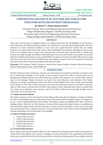
International Journal of Energy and Environmental ResearchVol.5, No.2, pp.55-73, June 2017Published by European Centre for Research Training and Development UK (www.eajournals.org)evaporation, washing and cleaning. A system without heat storage is economically feasible. Inthis case, the solar heat is forward directly into the desirable process. However, this system isnot economically feasible when heat is needed at the early or late hours of the day or atnighttimes. Most of the process heat is used in beverages, food and textile industry for differentprocesses as drying, cleaning, extraction and other different processes. Temperature level forthese applications may vary from ambient to low-pressure steam which can be provided eitherfrom flat plate or evacuated tube collector. The solar industrial process heat system uses thesame system components and mode of operation as solar domestic hot water system. Heatstorage is recommended to be added to the system so that the system can operate in periods oflow irradiation and/or nighttime. Hot water or low pressure steam at medium temperatures( 150 C) can be used either for preheating of water used for processes or for steam generation.The most common applications of industrial process heat has been introduced by Schweiger etal. [31]. In addition, he presented the history of solar industrial and agricultural processapplications as well as describing practical examples. Integration of solar heat systems intoindustrial applications requires storage and control strategies to handle the non-continuoussupply of solar energy [32]. Benz et al. [33] presented the details of two solar thermal systemsinstalled for producing process heat for a brewery and a dairy in Germany. The solar generationin both industrial processes is found to be comparable to the energy generated from solarsystems for domestic solar water heating or space heating.The main objective of the present work is to investigate thermal performance of evacuated tubesolar water collector in hot and harsh climate like Kuwait climate. An experimental test facilityis installed at the College of Technological Studies, Kuwait to record the thermal performanceof ETC through one year period. Linear regression analysis is adapted to correlate theexperimental data to collector thermal efficiency. In the present work, a detailed developednonlinear model for evacuated tube solar collectors is introduced with more comprehensiveoptical and thermal analysis. The variation of the temperature along both the circumferential(fin) and the longitudinal (tube) directions is considered in the present model. The predictednumerical values are compared with the experimental values obtained from experimental testfacility. The optimum design parameters; collector tube size, mass flow rate and collector tiltangle are determined based on year round ETC thermal performance under the meteorologicalcondition of Kuwait. Finally, the integration of evacuated tube collector to provide heat forindustrial processes like soft drink industry is evaluated.Experimental SetupFigure 1 shows a schematic diagram of the collector test facility, designed and constructed toconduct this work. It consists of evacuated tube collector (1), radiation pyranometer (2),anemometer (3), storage tank (4) of 100 liters capacity, cross flow heat exchanger (5), andconstant temperature circulator (6). A circulator pump (7) is employed to overcome thepressure resistance of the system, pressure relief valve (8), air vent (9). Flow meter (10) tomeasure mass flow rate, a control valve (11) is used to regulate the flow rate through the circuitwith the aid of a valve in the pump by-pass line. Filters (12) and several non-return valves (13)are fitted in the pipeline to define the flow direction.1. solar collector2. radiation pyranometer58ISSN 2055-0197(Print), ISSN 2055-0200(Online)
International Journal of Energy and Environmental ResearchVol.5, No.2, pp.55-73, June 2017Published by European Centre for Research Training and Development UK (www.eajournals.org)3. anemometer4. storage tank5. const. temp. circulator6. cross flow heat exchanger7. centrifugal pump8. pressure relief valve899. air vent10. flow meter11. flow control valve412. filter13. non return valve213312 12water makeup1513613131310 11Figure 1.712Schematic diagram of the collector test facility59ISSN 2055-0197(Print), ISSN 2055-0200(Online)
International Journal of Energy and Environmental ResearchVol.5, No.2, pp.55-73, June 2017Published by European Centre for Research Training and Development UK (www.eajournals.org)The circulator is fitted with standard RS232 interface enabling temperature control through thedata acquisition system. The heat exchanger is made from finned copper tubes with two fansto force the air across the tubes. The intensity of the global and diffuse solar radiation incidenton the collector surface (30 tilted) are measured and recorded by two Precision SpectralPyranometers. The pyranometer used to measure the diffuse solar radiation is fitted with ashading ring such that the detector is shielded from direct solar radiation to measure the diffuseradiation only.Three standard resistance thermometer detectors (RTD-PT100) are used tomonitor the surrounding ambient temperature, inlet and outlet fluid temperatures of thecollector.The water flow rate through the collector is measured using turbine flow meter suitable for 0.2to 5 liters/min with accuracy of 3%. The evacuated tube collector has an aperture area of 1.8m2 and is inclined 30 on the horizontal.A data acquisition system capable of recording 40 channels is used to record the instantaneousmeasurements of temperatures, flow rates and solar intensities and to control the collector inletfluid temperature through the constant temperature water circulator. The data acquisitionsystem has a resolution better than 0.01 C for thermocouple readings and for 4-wires RTDreadings. The experiments are carried out for global solar radiation between 600 and 1000W/m2, on a 30 -tilted collector surface with average ambient temperatures from 20 to 40 C.The inlet water temperature is changed from around the ambient temperature up to 85 C in10 C steps. The experimental procedure is started by flushing the system. Then, the system isfilled with water and the flow rate is adjusted to the required value. The solar collector isallowed to run for over 30 minutes (about 4 times the collector time constant) to achieve quasisteady-state conditions before the data collections were started. Each experiment continued for90 minutes, after that the inlet fluid temperature is changed and a new experiment is started.The collected data are examined to ensure that it presents quasi steady state conditionsaccording to the recommendations outlined by ASHRAE [34]. Knowing the inlet and outletfluid temperatures and the mass flow rate of water, the useful energy can be evaluated usingequation (1). The useful energy may also be expressed in terms of the energy gained by theabsorber and the energy lost from the absorber as given by equation (2). c p ( To Ti )Qu m(1)Qu ( τα ) A a G - UL A a ( Ti - Ta )(2)The instantaneous collector efficiency relates the useful energy to the total radiation incidenton the collector surface by equation (3) or (4).η c p ( To - Ti )mQu A aGA aGη FR [ ( τα ) - UL (Ti - Ta ) / G ](3)(4)The uncertainty analysis shows an experimental error of about 1.1, 1.2 and 2.9% for FRUL,FR( ), and the collector efficiency, , respectively. The uncertainty analysis, for theexperimental data fitted by equation 4, revealed that the optical efficiency, , is more sensitiveto experimental error than the heat loss coefficient, UL.60ISSN 2055-0197(Print), ISSN 2055-0200(Online)
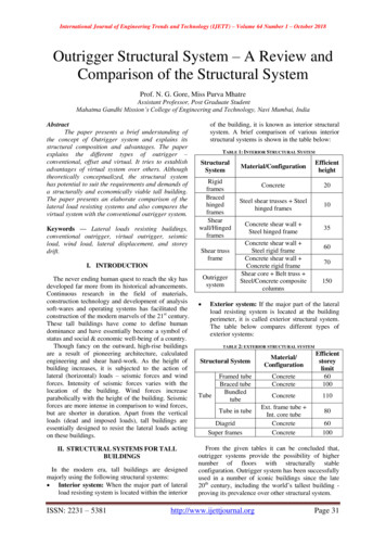
International Journal of Energy and Environmental ResearchVol.5, No.2, pp.55-73, June 2017Published by European Centre for Research Training and Development UK (www.eajournals.org)Theoretical Modeling of ETCEvacuated tube collector receiver consists of a copper U-tube inside a glass vacuumed tube.The copper tube is surrounded by a cylindrical aluminum fin pressed on it. This fin enhancesthe heat transfer area between the inner glass absorber surface and the U-tube. The workingfluid enters the collector inlet pipe, then it is evenly distributed to the U-tubes, absorbs heatand, at the end, it is returned to the outlet header pipe. The outer cylindrical glass transmits therays to the inner glass tube, which conducts the energy to the absorber fin. The energytransformed into heat is conducted by the fin to the copper U-tube and finally absorbed by theworking fluid, which is water in this case. Figure 2 shows a detailed schematic diagram of theevacuate tube and its cross section view.Figure 2. Schematic diagram of the glass evacuated tube solar collector with U-tubeOne dimensional analysis for the fin of a single unit of the glass evacuated tube solar collectoris carried out. To simplify the model, the following assumptions are considered: i) steady-stateconditions are considered with normal incidence angle of solar radiation; ii) thermal resistanceof the outer glass tube thickness is negligible; iii) perfect vacuum is assumed between the twoglass tubes, thus gas conduction is neglected; iv) an air layer of small thickness is consideredbetween aluminum fin and the absorber glass tube. The absorbed solar power (S), is equal tothe incident solar power times the optical losses and can be expressed as:S (τα)GAa(5)61ISSN 2055-0197(Print), ISSN 2055-0200(Online)
International Journal of Energy and Environmental ResearchVol.5, No.2, pp.55-73, June 2017Published by European Centre for Research Training and Development UK (www.eajournals.org)where is the glass cover transmittance, is the glass cover absorptance, G is the global solarirradiance on the collector surface and Aa is the collector aperture area. The theoretical modelis based on the heat balance equations for each part of the collector as follows:Outer glass tubehr g Lr g (Tr Tg ) hg a Lg (Ta Tg ) 0(6)where Tr, Tg, Ta are the inner glass tube temperature, outer glass tube temperature and ambienttemperature; hr–g is the heat transfer coefficient between the inner and outer glass tubes; and hg–a is the heat transfer coefficient between the outer glass tube and the ambient environment. Heatconduction can be ignored because the space between the inner and outer tubes is a very narrowvacuum layer, in which the vacuum level is 10-4 Pa and the heat conduction coefficient is lessthan 0.27 x 10⁻⁵ W/m C [34]. Considering hr–g hr–g,rad hr–g,cond, where hr–g,rad and hr–g,condare the radiation and conduction heat transfer coefficients between the outer and inner glasstube Also, hg–a hg–a,rad hg–a,conv, where hg–a,rad and hg–a,conv are the radiation and convectionheat transfer coefficients between the outer tube and the ambient environment, and hg–a,conv isa function of the wind velocity. Lr–g (Lr Lg)/2, where Lr and Lg are the perimeters of theinner and outer glass tubes.Inner glass tubehr g Lr g (Tg Tr ) hr Al Lr Al (TAl Tr ) Qe τg αr Dg G 0(7)where TAl is the aluminum fin temperature; and hr–Al is the total heat transfer coefficientbetween the inner glass tube and the aluminum fin, and hr–Al hr–Al,rad hr–Al,cond, where hr–Al,rad and hr–Al,cond are the radiation and conduction heat transfer coefficients between innerglass tube and aluminum fin, τg is the transmission coefficient of the outer glass tube; τr is theabsorption coefficient of the selective coating on the inner glass tube; dg is the diameter of theouter glass tube; G is the total solar irradiance on the collector aperture surface; Lr–Al (Lr LAl)/2, where LAl is the perimeter of aluminum fin, and Qe is the heat loss of the tube edge tothe manifold.Aluminum Finhr Al Lr Al (Tr TAl ) hAl Cu LCu (TCu TAl ) 0(8)where TCu is the U copper pipe temperature; and hAl–Cu is the total heat transfer coefficientbetween the aluminum fin and U copper pipe, hAl–Cu hAl–Cu,rad hAl–Cu,cond, where hAl–Cu,rad andhAl–Cu,cond are the radiation and conduction heat transfer coefficients between the aluminum finand U copper pipe, and LCu is the perimeter of the copper pipe.U copper pipehAl Cul LCu (TAl TCu ) hf LCu (Tf TCu ) 0(9)62ISSN 2055-0197(Print), ISSN 2055-0200(Online)
International Journal of Energy and Environmental ResearchVol.5, No.2, pp.55-73, June 2017Published by European Centre for Research Training and Development UK (www.eajournals.org)where hf is the fluid convective heat transfer coefficient inside the U copper pipe and it varieswith flow velocity.Working fluidhf LCu (TCu Tf ) x ṁcp (Ti To ) 0(10)where Ti and To are the inlet and outlet temperatures of working fluid in the U copper pipe andx is the interval of the fluid along the tube axis. ṁ and cp are the mass flow rate and specificheat capacity of the working fluid.The radiation heat transfer coefficient (hr–g,rad) between the outer and inner glass tube is givenby:hr g,radσ(Tr2 Tg2 )(Tr Tg ) 11εr εg 1(11)where r and g are the emission coefficients of the inner tube selective coating and glass ofthe outer glass tubes, respectively. Under the conditions given by the industrial temperaturerange, the ambient air can be treated as a transparent body of heat radiation, so that hg–a,rad canbe ignored.The convection heat transfer coefficient (hf) between the fluid and the U-pipe wall can beexpressed as [35]:hf f Nu f 1.75 [Gz 5.6DD 10 4 (GrPrLT)D10.7 3] (μav 0.14)μwall(12)where Nu is Nusselt number, Gz is Graetz number, Pr is Prandtl number, LT is the length ofthe tube, D is equivalent diameter for the theoretical model, µav and µwall are the viscosity offluid at average fluid temperature and wall temperature and f is the thermal conductivity ofthe fluid.The previous equations are adapted to develop a theoretical model to predict the performanceof evacuated tube collector under different climatic conditions.63ISSN 2055-0197(Print), ISSN 2055-0200(Online)
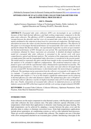
International Journal of Energy and Environmental ResearchVol.5, No.2, pp.55-73, June 2017Published by European Centre for Research Training and Development UK (www.eajournals.org)RESULTS AND DISCUSSIONSEvacuated Tube Collector PerformanceA comparison between the ETC performance predicted by the present model and thecorresponding performance resulted from linear regression of experimental data is presentedin Figure 3 for reduced temperature, (Ti-Ta)/G, ranging from 0 to 0.08 m2 K/W.0.8ModelExperimental0.7 i -Ta )/G (m 2K/W)Figure 3. Comparison between simulated and experimental ETC thermal efficiencySimulations are carried out under different test conditions to obtain the collector efficiencycurve shown in Figure3. The weather data adapted for present work is the hourly values ofglobal radiation and ambient temperature measured for a period of two years in the College ofTechnological Studies, Kuwait.The efficiency curves obtained from the present model and experimental data fitting are: model experiment 0.718 3.19 0.699 3.30(Ti Ta )G(Ti Ta )G(13)(14)Error analysis revealed that the maximum deviation between model and experimental opticalefficiency is about 2.6% while the maximum deviation between model and experimental64ISSN 2055-0197(Print), ISSN 2055-0200(Online)
International Journal of Energy and Environmental ResearchVol.5, No.2, pp.55-73, June 2017Published by European Centre for Research Training and Development UK (www.eajournals.org)overall heat loss coefficient is approximately 3.3%. The above graph and these predictionsclearly demonstrate the reliability of the present developed ETC numerical model.After validation and checking reliability, the theoretical model is employed to determineoptimum collector parameters. Figure 4 presents the variation of the annual energy productionfrom collector for various collector orientations. The slope of the collector is changed from 0 to 60 (i.e. latitude 30 ). In addition, different azimuth angles are examined ranging from 0 (due south) to 40 west of south. Each combination of slope and azimuth angle is examined ina single simulation period which is one year.5400Annual Energy Generation (MJ/year)Azimuth 0 deg.Azimuth 20 deg.Azimuth 40 llector Tilt (degrees)Figure 4. Variation of Annual energy generation with collector tiltAs seen from the figure, the energy production changes with both collector orientation andazimuth angle. It is obvious that the maximum energy generation from the collectorcorresponds to tilt equal to 25 (i.e. latitude -5 ) and for collector facing south (azimuthangle 0 ). Maximum energy production at angles greater than latitude is in accordance withthe fact that more solar energy is available in summer than in winter in Kuwait. So, annualenergy production can be maximized by using collector sloped at an angle of 25 .In spite of the significant effect of tube length and tube diameter on the thermal efficiency andthe manufacturing costs of evacuated tube collectors, few studies are carried out to analyze thiseffect. So, it is of high importance to analyze the thermal efficiency variation as function ofthe tube size. The variation of the thermal efficiency with different tube lengths is studied.65ISSN 2055-0197(Print), ISSN 2055-0200(Online)
International Journal of Energy and Environmental ResearchVol.5, No.2, pp.55-73, June 2017Published by European Centre for Research
a forced circulation solar water heating system. Water was used as the working fluid in the system and the maximum outlet temperature of water was recorded as 70.3 while 59.5 was recorded at the bottom of the hot water tank. Measurements obtained revealed that the heat pipe ETCs are more efficient than FPCs of a solar water heating system.