Transcription
conduitCONSTRUCTION GUIDEFor the installation of conduit, manholes and splice boxes1
One call to Miss Utility cansave time, money and lives.Before you pick up any equipment, pick up the phone and call Miss Utility. Miss Utilitywill notify all applicable utility companies and see to it that your job site is marked for allunderground utility lines. One simple phone call can save you the time and hassle ofdealing with job site mistakes and delays. Not to mention decrease liability, prevent damage,reduce injuries and possibly save lives. After all, safety is everyone’s job.Call Miss Utility, at least 48 hours prior to work, at 811 or 800.257.7777.DIG SAFELY CHECKLIST:1 Call Miss Utility at 811 or 800.257.7777 at least 48 hours prior to work.2 Allow the required time for utilities to mark the underground lines.3 Respect and protect all marks/flags.4 Excavate with care. Take all reasonable actions to properly protect,support and backfill underground utility lines.5 Immediately notify the utility if an underground utility line is damaged.6 If damage creates an emergency, take immediate steps to safeguard life, health and property.Please check with your individual jurisdictions with regard to waiting times andspecific digging guidelines.For more information, contact Miss Utility or check online at MissUtility.net.Call before you dig, every dig.It’s the law.MISS UTILITY 811 or 800.257.77772
IntroductionThe information in this manual provides general guidelines for the installation of conduit,manholes and splice/pull boxes as it relates to BGE gas and electric service.These guidelines assist developers, general contractors, builders, architects, engineers,licensed electricians and plumbers in the engineering, planning and construction ofcommercial, industrial and residential projects.This addendum provides clear and more consistent guidelines on the requirements forconduit and manhole construction. This publication does not cover all the rules and regulationsand is to be used in conjunction with the “Commercial, Industrial and Residential CustomerInformation Booklet”. For your convenience both booklets are available online at BGE.COM.BGE’s goal is to work with you to install gas and electric service promptly and safely whilemeeting all construction codes and safety standards. Now and in the future, we’re committedto providing safe and dependable natural gas and electric service.We hope the information in this manual answers your questions and guides you throughthe process. If there’s anything we haven’t made clear, please call us at 800.233.1854.A PDF version of this manual can be found on the Service Request section ofBGE.COM/MyAccount/MyService.3
Table of Contents1. GENERAL INFORMATIONGuidelines.6Customer Responsibilities. 6-72. CONDUITSpecifications for Customer Installation. 9-11Standard Duct Bank Arrangement/Installation.11Plastic PVC Duct Spacers General Information.12Road Crossing Specifications.133-Phase Transformer Pad Dimensions Detail.141-Phase Transformer Pad Dimensions Detail.15Turning Conduit into Transformer Pads.163. SPLICE/PULL BOXESGeneral Information.18Secondary (600V) Fiberglass Splice/Pull Box.19Installation Instructions for 13 and 34 kV Boxes.20Splice/Pull Box - 13kV (#2- 1/0 cables only).21Splice/Pull Box - 13kV (#2- 500 cables only).22Splice/Pull Box - 2-sets 13kV or 1- set 34kV (#2- 750 cables). 23-244. MANHOLESGeneral Information.26Installation of Precast Concrete Manholes . 26-27Small Secondary Manhole 1 to 4 Services. 27-29Large Secondary Manhole 1 to 7 Services. 30-31Precast Concrete Line Manholes. 32-33Precast Concrete Slotted End Wall Manhole. 34-36Installation Standards. 37-43Materials Available from BGE.445. DEFINITIONS AND FREQUENTLY ASKED QUESTIONSDefinitions. 47-48Frequently Asked Questions. 48-494
generalinformation5
General InformationGuidelinesBGE’s Underground Cable SystemsBGE’S UNDERGROUND CABLE SYSTEMSARE DIVIDED INTO THREE TYPES:1. Direct-Buried:(Cables/Gas Pipe installed directly in ground, notinstalled in any type of duct or sleeve)This type of system is typically used in urbanareas where: Load density is significant. Concentration of circuits via the same routeare planned or expected. Additional circuits will be added routinely.This type of system is typically used in rural orsuburban areas where: The concentration of circuits, limited Right-ofways and an expected high number of circuitsleaving distribution or master substations. Load density is relatively light; a concentrationof cables does not exist. Ducts are stacked on top each other. Circuits are not routinely added and front lotline installations. Dirt digging with occasional paving is expected. In these areas, the design principle used is loopfeed primary and joint trenching with telephoneand gas. Sleeving (short duct lengths) may be used inadvance of paving where BGE utilities are tobe installed at a later date (i.e. road crossings,parking lots, etc.).2. Direct-Buried Conduit:(cables/gas pipe installed in PVC or flex polyethyleneduct or sleeve that is installed directly in ground)This type of system is typically used in rural orsuburban areas where special situations existsuch as: Extensive paved areas with concrete or macadamsuch as parking lots. Secondary distribution through paved, limitedaccess, congested or potentially congestedareas, thus preventing easy maintenance diggingfor repairs or replacement of the installed lines. Rocky soil conditions which could damagethe cable.NOTE: Typically used in conjunction with splice/pullboxes and not concrete manholes.63. Concrete Encased Conduit:(Cables installed in concrete encased PVC duct)NOTE: Typically used in conjunction with concretemanholes and not splice/pull boxes.NOTE: Gas sleeves will not be concrete encased.Customer ResponsibilitiesThe information provided below is an addendum forconduit and manhole construction only. Please referto the “Natural Gas and Electric Service Guide”for the comprehensive list of rules, regulationsand responsibilities.The customer is responsible for engineering,designing, permitting, purchasing and constructingall required road crossings, ducts, conduit, splice/pull boxes and manholes according to the standardsset forth in this document in order for BGE toprovide gas and electric service.Customer’s responsibility toperform the following:Pre-Construction Phase Submit BGE service application and obtainproject number (Service Request or Work Order#). Provide loads and voltage class. Provide detailed utility site plans.
1 Meet with BGE representative to discuss projectscope, schedules and next steps. Develop detailed conduit and manhole drawingsincluding profiles and duct runs.** Submit conduit and manhole drawings toBGE for review.** Submit drawings to local municipality and obtainrequired permitting. Sign and return required BGE design drawingsand contract. Provide payment to BGE for project costs. Contact inspector noted on BGE design drawingsto schedule pre-construction meeting.Construction Phase Notify BGE immediately of any changesto schedule, scope or final design. Contact BGE to schedule“Pre-pour Inspection.” ** Contact BGE to schedule “Pre-backfillInspection.” ** Contact BGE to schedule “Mandreling andStringing Inspection.” **Post Construction Phase Satisfy all municipality inspections. Call BGE to schedule and release BGE project.** When indicated on BGE drawings.NOTE: Not following specifications and standards inthis booklet may cause delays in customer projectand additional costs necessary for BGE tocomplete the job.7
conduit8
ConduitSpecifications for CustomerInstallationNOTE: Conduit from the meter termination pointto the secondary side of the transformer is thestandard method of installation for most three-phasecommercial and industrial secondary services.The direct-buried method is still a method ofinstallation where conduit installation would beimpractical. When required by BGE, the customeris responsible for designing and building ductsand conduit systems.Direct-Buried Electric ConduitPrimary and Secondary Electric Conduit1. Secondary conduit will be 4” minimum insidedimension I.P.S.2. Primary conduit size varies, contact BGErepresentative for actual sizes.3. BGE shall specify the number, size andconfiguration of ducts.4. All direct-buried ducts shall be UL schedule 40.5. All bends shall be no less than 36” in radius.A total of two (2) 90-degree bends are allowedin the conduit line (i.e., conduit turn up attransformer pad is one (1) 90-degree bend).One (1) additional, wide-radius bend (minimumradius of five feet for this additional bend) will beallowed. If this still will not be sufficient for theconduit design/construction, contact your BGErepresentative. A hand hole, splice/pull box ormanhole may be required.6. The customer shall pull a mandrel (1/2” smallerin diameter than the conduit and 6” long)through each duct prior to BGE cableinstallation, followed by a pulling line (1800 lb.minimum tensile strength mule line preferred)which shall remain in each duct.7. Customers will connect all electric conduitwith sealed/glue couplings and terminate theirconduit with bell ends and plugs.28. Electrical ducts should be sloped away from thecustomer’s building whenever possible to reducethe potential for water intrusion into the buildingas a result of failed or missing duct seals.9. Required depth of conduit from final grade totop of conduit/conduit bank: 30” for secondary, minimum 36” for primary, minimum 48” maximum10. Backfill evenly around duct with clean dry earthand mechanically tamp in 12” lifts.11. Lengths of secondary duct banks shall beminimized to limit pulling distances andelectrical losses. Any secondary duct lengthsover 100 feet shall be approved by BGE priorto construction.12. The minimum longitudinal separation betweenforeign structures and conduit should beas follows: Telephone/Cable Television Conduit–3”of concrete or 12” of earth Gas, Water, Sanitary and Oil Mains–12”of earth13. Splice/pull boxes or manholes may be requiredby BGE depending on the specific installation.14. If electric service is being supplied from a newtransformer, the customer’s duct shall enter thetransformer as shown on page titled “TurningConduit into Transformer Pads” in section two (2)of this booklet.15. If electric service is being supplied from anexisting transformer, the customer shall end thesecondary duct five feet from the secondaryside of the transformer at a location determinedby BGE. BGE will continue the duct into thetransformer based on field conditions.Direct-Buried Gas Sleeves1. PVC UL Schedule 40 conduit (solid wall, notsplit) may be used as a sleeve installed inadvance of paving to facilitate future installation9
Conduitof small size (2” and smaller) gas services wherecasing is not required. The ends of the sleeveshould not be sealed after insertion of the carrierpipe to avoid containment of gas in case of a gasleak. However, the end of the sleeve on a serviceline nearest the building should be sealed afterinstallation of the carrier pipe and the oppositeend of the sleeve left open.2. Gas services common trenched with electric ductshall be in sleeves.3. Gas sleeves shall not exceed one 45-degreebend and must terminate a minimum of 5’ fromall buildings/ structures. NOTE: 90-degree bendsare not allowed.4. Only one gas service per sleeve is permitted.5. Gas sleeves will not be concrete encased.6. Installation of gas piping into any electricalconduit bank is prohibited.7. Installation of minimum 4” sleeve andunderground warning tape unless otherwisespecified for natural gas service under paving, orunder improved areas as required by BGE or anycity or county regulations. (Applicable only forplastic gas service sizes: 1/2” CTS; 3/4” IPS; 1”CTS; 1-1/4” CTS; 1-1/4” IPS and 2” IPS.)8. Lengths of continuous runs for gas sleeves shallnot exceed 300 feet.9. Mechanical joints on gas services are notallowed inside of sleeves. Open trench spaceprovision must be made to allow BGE room tomake these connections.10. Warning tape is required above all gas sleevesand can be purchased from the BGE warehouseby calling 410.470.7813.11. PVC sleeves for gas shall be two (2) standardpipe sizes larger than the gas pipe.12. Vertical separation for gas sleeves when crossingany foreign structure is a minimum of 12”.13. Radial separation between gas sleeves andelectric cable or conduit is a minimum of 12”.10Concrete Encased Electric Conduit1. Duct banks must be concrete encased if anyducts are stacked vertically (one on top of theother). All 2x2 duct banks and greater must beconcrete encased.2. If ducts are within municipality Right-of-way,it may be required to concrete-encase. Checkwith local Department of Public Works forspecific requirements.3. BGE shall specify the number, size andconfiguration of ducts.4. Schedule 20 PVC must be used for concreteencased ducts.5. Bends shall be no less than 36” in radius. A totalof two (2) 90-degree bends are allowed in theconduit line. If this still will not be sufficient forthe conduit design/construction, contact yourBGE representative. A manhole, splice/ pull boxor hand box may be required.6. Duct spacers that maintain a 2” separationbetween ducts are required every 6 1/2 - 7’.Required depth of conduit from final grade totop of conduit/conduit bank (unless otherwiseapproved by BGE): 30” for secondary, minimum 36” for primary, minimum 48” maximum7. Only standard 2,500-psi ready-mix concrete with1/2” pea gravel will be approved for encasement.8. After concrete cures for 24 hours, backfill aroundduct bank with clean select soil and mechanicallytamp in 8” lifts.9. The customer shall pull a mandrel (1/2” smallerin diameter than the conduit and 6” long)through each duct prior to BGE cable installation,followed by a pulling line (1800 lb. mule linepreferred), which shall remain in each duct.10. Secondary customer switchgear installationsthat incorporate metering compartments thatare supplied by eight or more ducts, requirea pit to be installed under that compartment.
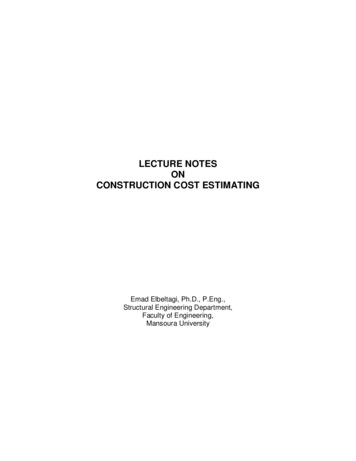
2The pit shall be 2’ deep and measure 1” lessthan the width and depth of the compartment.Ducts must enter the pit from the bottom, not thesides. Refer to the BGE Gas & Electric MeteringManual under the New Construction Servicessection available at BGE.COM for more details.12. If electric service is being supplied from anexisting transformer, the customer shall end thesecondary duct five feet from the secondaryside of the transformer at a location determinedby BGE. BGE will continue the duct into thetransformer based on field conditions.11. If electric service is being supplied from a newtransformer, the customer’s duct shall enter thetransformer as shown on page titled “TurningConduit into Transformer Pads” in section two (2)of this booklet.Standard Duct Bank Arrangement/Installation2W X 1H3W X 1H6"- 21"6"-29 1/2"5"- 19"5"4"-26 1/2"23 1/2"3"5"- 11 1/2"3"3"2"6"- 12 1/2"3"5"- 11 1/2"3"4"- 10 1/2"3"3"2"4"- 10 1/2"3"4W X 2H6"- 12 1/2"4"- 17"6" - 38"5" - 34"4" - 30"3W X 2H3"5"- 19"3"23 1/2"2"3"3"2"26 1/2"4"-5"- 19"6"- 21"2"5"- 19"4"-23 1/2"3"Duct SpaceTypical3"5"- 26 1/2"6"- 29 1/2"4"- 23 1/2"4"- 23 1/2"5"- 26 1/2"6"- 29 1/2"3"3"2"2"2"3"2"3"3"2"3"6"- 38"3"3"29 1/2"26 1/2"5"- 34"4"- 17"6"5"-3"5"- 19"4"- 17"4"- 30"6"- 21"2"6"- 21"3W X 3H2W X 3H3"4"- 17"3"5"- 19"6"- 21"2W X 4H3"2"4"- 17"3"3"3"3"5"-2"6"- 21"5"- 19"4"- 17"29 1/2"3"6"- 21"6"-3"4"- 17"2W X 2H11
ConduitPlastic PVC Duct Spacers General InformationGeneral InformationA. Duct spacers are used to hold PVC ducts inposition and maintain a 2” separation betweenadjacent ducts while pouring concrete.CapCapIntermediateB. There are 3 basic parts to the duct spacers—the base, intermediate, and cap. If required,there are also pads/feet that can be used with5” and 6” spacers for extra support in anunstable trench bottom.IntermediateBaseC. Standard cover for a primary conduit systemis 36” and 30” cover for a secondary conduitsystem. Both of these dimensions are measuredfrom final grade to the top of the concreteenvelope of the duct.36" cover for primaryD. Reinforcing bars are used to stabilize30" cover for secondarythe duct and spacers when theconcrete is poured. Drive #4 reinforcing36" cover for primary30" cover for secondarybars through the inside edges of theduct spacers and at least 6” intothe trench bottom.#4 Reinforcing BarsFinal Grade#4 Reinforcing BarsTrenchWallTrench Wall3"3"20' length6.5'to 7'3" Trench Wall3"Reinforcing barsdriven at least 6"into trench bottomReinforcing barsdriven at least 6"into trench bottomF. To properly support multiple ducts in a trench,the duct spacers are separated approximately6-1/2’ to 7‘ apart. Since PVC duct is manufacturedin 20’ lengths, this means there are three (3)spacers installed within one section of duct.12PadsFinal GradeTrenchWallE. The sides of the trench are used asretaining walls when the concrete is poured.The distance from the outer duct diameterto the trench wall should be 3” wide. This inturn gives the required 3” apron around thewhole duct bank.6.5'to 7'BasePads6.5'to 7'Duct Spacers
2Road Crossing SpecificationsNOTES: A minimum 12” radial separation must be maintained between gas and any other utility. Allow a minimum 6” separation between primary ducts or between primary and secondary ducts. Place an electronic marker 12” above the end of the PVC duct crossing(s).Final Grade of Road SurfaceElectronic Marker24”MinimumGas MainConsult BGE if gas mainis larger than 2” plasticStreetLightCable49.5” Minimum 60” MaximumTelephone &CATV e(s)Allowance for Rock BottomNOTES: All ducts to be 4” PVC SCH 40 unless otherwise noted. Ducts must extend a minimum 5’ beyondproposed paving. Place an electronic marker 12” above the end of each PVC duct crossing(s). Install a PVC duct plug on the end of each duct rker13
Conduit3-Phase TransformerPad Dimension Detail/Conduit DetailNOTES:A. The number of secondary 4” conduit shall notexceed 12 total.B. Approximate weight of precast pad is 2200pounds for 500kVA and smaller transformers(No. 12-668) or 4120 pounds for 750kVA andlarger (No. 12-790).C. Customer to install a ½’ x 8’ copper-clad groundrod as required, avoiding in-coming conduit.D. (No. 12-668 & No. 12-790) numbers refer to BGEMaterial Numbers.14E. Pad No. 12-790 has two knockouts that allowthe 50” opening dimension to be increased to amaximum of 66”.F.If the duct count exceeds nine, the ducts shallbe banded together within the transformerpad opening to ensure all ducts remain in theircorrect spaces within the transformer.G. Transformer pads can be purchased anddelivered to your site by calling the BGEwarehouse at 410.470.7813.H. If electric service is being supplied from anexisting transformer, the customer shall endthe secondary duct five feet from the secondaryside of the transformer at a location determinedby BGE. BGE will continue the duct into thetransformer based on field conditions.
21-Phase Transformer Pad Dimension Detail/Conduit Detail33NOTE:If electric service is being supplied from an existing transformer, the customer shall end the secondary ductfive feet from the secondary side of the transformer at a location determined by BGE. BGE will continue theduct into the transformer based on field conditions.15
Note: If electric service is being supplied from an existing transformer, the customer shall end theTurning Conduit into Transformer PadsConduit162Turning Conduit into Transformer Pads
1splice/pullboxes17
Splice/Pull BoxesSplice/pull boxes are primarily utilized on 13kV or34kV direct-buried or directional bored polyethyleneflex or PVC duct installations. For economic reasons,splice/pull boxes are not intended to be used fordirect- buried or concrete encased duct systems.The intent of a splice/pull box is to provide anenclosure in which to install splices or assist in cablepulling operations when duct runs exceed the reellength of a certain cable, or the duct run exceeds theallowed number of bends. Splice/pull boxes can alsobe used to break into and extend from existing 13kVor 34kV duct systems to maintain the connectivity ofthe duct system.Customers must only install BGE approvedsplice/pull boxes and should consult with a BGErepresentative prior to design and installation.When required, customers are responsible forpurchasing, engineering, designing andconstructing all ducts and splice/pull boxes.NOTES18There are various sizes and styles of splice/pullboxes. Depending on the specific situations andapplications, there are approved splice/pull boxesfor 600V, 13kV or 34kV systems and load bearingand non-load bearing applications.With the exception of the secondary splice/pull box(12-647) all splice/pull boxes are rated for heavyvehicular traffic in parking lots and driveways.They are designed to safely support the weight ofoccasional, slow moving traffic. They are notrated for frequent, fast moving traffic in street orhighway applications.
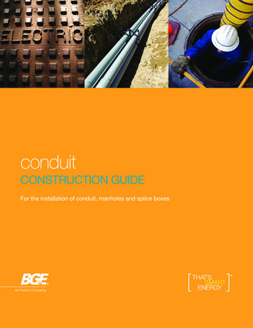
3Secondary (600v) FiberglassSplice/Pull Box—Pedestrian(Grassy) Areas Only—1 to 7 ServicesOUTSIDE DIMENSIONS: 50”W X 56”L X 32”H,APPROX. WEIGHT: 100 LB.MAT’L NO: 12-647NOTES:This fiberglass splice/pull box cannot be used inBaltimore City.4. Ducts can only enter and exit the splice/pullbox at opposite ends from each other. Whennecessary, the existing 6”x6” openings in theend walls can be enlarged to accommodatemultiple ducts (maximum opening 16”W x 10”H).This enlarged opening will allow up to six 4”diameter ducts (3W x 2H configuration) to enteror exit this box. However, only a maximum ofeight ducts can be joined to this splice/pull boxat any time, one for the secondary main and upto seven for service cables.For Baltimore City and traffic rated secondary splice/pull boxes see concrete manhole section.5. Install the ducts no more than 2” into the splice/pull box. Use aerosol foam sealer or duct sealingcompound around the ducts on the outside ofthe splice/pull box to seal openings.1. This fiberglass splice/pull box must be installedonly in pedestrian (grassy) areas on level ground.It must not be installed on a hill or slope.6. Place a block of wood over side wall openingswithout ducts, on the outside, to prevent backfillfrom entering the confines of the splice/pull box.2. Stabilize the bottom of the excavation with 6” ofpea gravel. The bottom flange of the splice/pullbox must be on a firm level foundation.7. Once the box and duct are installed, the covershould be securely fastened to the enclosureduring backfill compaction. This action willprevent any distortion of the sidewalls whilethe box is being backfilled.3. Position the enclosure in the excavation sothat the cover will be flush with final grade. Seediagram below.8. Backfill evenly around the splice/pull boxwith clean, dry earth and mechanically tampin 8” layers.PentaheadBolt24" MIN.32"Final Grade2"6"6" x 6"SidewallOpening2"NOTE:Up to a maximum of six4” diameter ducts canexit the box's extendedopening of 16"W x 10"H6" Minimum Pea Gravel10"Fiberglass Splice/Pull Box(Mat'l No. 12-647)PrView16"19
Splice/Pull BoxesInstallation InstructionsFor 13 and 34 kV Boxes1. Locate within 30’ of a truck accessiblepaved surface.2. Install in an area that will be easy to locate andeasy to access.3. Do not install on slopes or in areas that willbecome overgrown with vegetation.4. Do not install in swales or areas that areprone to flooding.5. Install a minimum 6” of pea gravel at the bottomof the excavation for water drainage.6. Install so that the top of the box is level and atfinal grade. If pavement is to be placed aroundthe enclosure, leave enough of the sidewallsexposed to account for paving.NOTES207. Slope the final grade away from the enclosureto match the surrounding grade.8. Insert the duct into the factory installed ductterminators in the end or side walls or cut outa circular hole to accept either the 4” or 6”duct. Do not cut this hole too large becausethe opening has to be moisture sealed.9. Insert duct a minimum of 1” and a maximumof 2” inside the box.10. Seal around the outside of the duct andterminators using aerosol foam sealer or ductsealing compound to prevent debris fromentering into the box.11. Securely fasten cover to box before backfillingto prevent distortion of the sidewalls.12. Backfill evenly around the splice box with clean,dry earth and mechanically tamp in 8” layers.
Box & Cover Section64- 3 8 "(Minimum 6" Pea Gravel for Water Drainage)Box - Plan View64"60"Box Cover atFinal Grade30"36"34- 12 "34- 14 "11"Two Piece CoverCover HandlesEnd ViewELECTRICPlace Splice/Pull Box in Level Ground Only1/2" Bolt forLifting SlingELECTRIC3Splice/Pull Box - 13kV (#2- 1/0 Cables Only)OUTSIDE DIMENSIONS: 35”W X 64”L X 36”H, APPROX. WEIGHT: 531 LB.MAT’L NO: 12-F6321
22Box & Cover Section85"(Minimum 6" Pea Gravel for Water Drainage)Box - Plan View86"81-3/4"36"Box Cover atFinal Grade51-3/4"56"55"56"Two Piece CoverEnd ViewELECTRICCover Handles1/2" Bolt forLifting SlingELECTRICPlace Splice/Pull Box in Level Ground OnlySplice/Pull BoxesSplice /Pull Box - 13kV (#2- 500 Only) CablesOUTSIDE DIMENSIONS: 56”W X 86”L X 36”H, APPROX. WEIGHT: 894 LB.MAT’L NO: 12-E23
Cable Entrance81– 3/4”86”SpliceOnly installdirectional bore ductBox & Cover Section85”(Recommended 6” Pea Gravel orCrush stone bottom for water drainage)Box — Plan ViewGroundRodSplice on opposite wallif cable is looped56”Mat’l No. 12–E23Weight 894 Lbs.36”Box Cover atFinal Grade51-3/4”55”56”Two Piece Cover81–1/4”End ViewELECTRICCover HandlesELECTRICPLACE SPLCE/PULL BOX IN LEVEL GROUND ONLY1/2” Bolt forLifting Sling51–1/2”3Splice /Pull Box - 2-Sets 13kV or 1- Set 34 kV (#2- 750 Cables)OUTSIDE DIMENSIONS: 56”W X 102”L X 34”H, APPROX. WEIGHT: 1322 LB.MAT’L NO: 12-E2423
Splice/Pull Boxes3TOP VIEWSplice/Pull Box - 2-Sets 13kV or 1- Set 34kV (#2- 750 Cables)(Cont’d.)24
2manholes25
ManholesPrecast concrete manholes are primarily utilizedon 600V, 13kV or 34kV concrete encased conduitsystems that require a heavy vehicular traffic rating.The intent of a manhole is to provide a housing inwhich to install splices or assist in cable pullingoperations when duct runs exceed the reel length ofa certain cable, or the duct run exceeds the allowednumber of bends. Manholes can also be used tobreak into and extend from existing 13kV or 34kVconduit systems to maintain the connectivity ofthe system.Manholes are typically used in urbanareas where: The concentration of circuits, limited Right-of-wayand municipality requirements necessitate theconduit system be in roadways and alleys. Submit conduit and manhole drawings to BGEfor review.** Submit drawings to local municipality and obtainrequired permitting. Contact inspector noted on BGE designdrawings to schedule pre-construction meeting. Contact BGE to schedule “Pre-pour Inspection”.** Contact BGE to schedule “Pre-backfillInspection”.** Contact BGE to schedule “Mandreling andStringing Inspection”.** Notify BGE immediately of any changes toschedule, scope or final design.** When indicated on BGE drawings. Load density i
electrical losses. Any secondary duct lengths over 100 feet shall be approved by BGE prior to construction. 12. The minimum longitudinal separation between foreign structures and conduit should be as follows: Telephone/Cable Television Conduit–3” of concrete or 12” of ea