Transcription
The Airbus safety magazineSafetyfirstSPECIAL EDITIONControl YourSpeed Series
Safety First, Special Edition, Control yourSpeed Series February, 2018. Safety firstis published by Airbus S.A.S. - 1, rond pointMaurice Bellonte - 31707 Blagnac Cedex/France.Publisher and Editor: Yannick Malinge,Chief Product Safety Officer.Concept Design by Airbus Multi Media Support20180245. Reference: X00D16031905 SpecialEdition 2. Photos by Airbus, A. Tchaikovski, S.Ramadier, P. Masclet, Lindner Fotografie, P.Pigeyre, JB. Accariez, A. Doumenjou, H. Gousse,F. Lancelot. Computer renderings by Fixion.This brochure is printed on Stucco.This paper is produced in factories that areaccredited EMAS and certified ISO 9001-14001,PEFC and FSC CoC. It is produced using pulpthat has been whitened without either chlorineor acid. The paper is entirely recyclable and isproduced from trees grown in sustainable forestresources.The printing inks use organic pigments orminerals. There is no use of basic dyes ordangerous metals from the cadmium, lead,mercury or hexavalent chromium group.Safety firstThe Airbus magazine contributing to the enhancementof the safety of aircraft operations by increasing knowledgeand communication on safety related topics.Safety first is published by the Product Safety department.It is a source of specialist safety information for the useof airlines who fly and maintain Airbus aircraft. It is alsodistributed to other selected organizations and is availableon digital devices.Material for publication is obtained from multiple sourcesand includes selected information from the Airbus FlightSafety Confidential Reporting System, incident and accidentinvestigation reports, system tests and flight tests. Materialis also obtained from sources within the airline industry,studies and reports from government agencies and otheraviation sources.Editorial TeamGuillaumeESTRAGNATTimothyROACHDanielPERCY Airbus S.A.S. 2018 – All rights reserved.Proprietary documents.By taking delivery of this Brochure(hereafter “Brochure”), you accept on behalfof your company to comply with the followingguidelines:No other intellectual property rights are grantedby the delivery of this Brochure than the right toread it, for the sole purpose of information.This Brochure and its content shallnot be modified and its illustrationsand photos shall not be reproduced withoutprior written consent of Airbus.This Brochure and the materials it containsshall not, in whole or in part, be sold, rented, orlicensed to any third party subject to payment.This Brochure contains sensitive informationthat is correct at the time of going to press.This information involves a number of factors thatcould change over time, effecting the true publicrepresentation. Airbus assumes no obligationto update any information contained in thisdocument or with respect to the informationdescribed herein.Airbus S.A.S. shall assume no liability for anydamage in connection with the use of thisBrochure and of the materials it contains, even ifAirbus S.A.S. has been advised of the likelihoodof such damages.All articles in Safety first are presented for informationonly and are not intended to replace ICAO guidelines,standards or recommended practices, operator-mandatedrequirements or technical orders. The contents do notsupersede any requirements mandated by the State ofRegistry of the Operator’s aircraft or supersede or amendany Airbus type-specific AFM, AMM, FCOM, MMELdocumentation or any other approved documentation.Articles may be reprinted without permission, except wherecopyright source is indicated, but with acknowledgementto Airbus. Where Airbus is not the author, the contents ofthe article do not necessarily reflect the views of Airbus,neither do they indicate Company policy.Contributions, comment and feedback are welcome. Enquiriesrelated to this publication should be addressed to:AirbusProduct Safety department (GS)1, rond point Maurice Bellonte31707 Blagnac Cedex - FranceFax: 33(0)5 61 93 44 29safetycommunication@airbus.comSafety first app available here
SafetyfirstSPECIAL EDITIONPROCEDURESP04Control your Speed. at take offP16Control your Speed. during climbP24Control your Speed. in cruiseP40Flight operationsControl your Speed. duringDescent, Approach and Landing
ARTPHONESSMARTPHONESOnOniOSiOSandandAndroidAndroid
Safety first - Special Edition February 2018Forewordln these articles, we detail everything that flight crews always wanted to knowabout speeds, but were afraid to ask.Our objective is to highlight the design and operational considerations underlyingall of the recommendations already published in Airbus documentation.We aim to provide some reminders about how the various speeds are elaboratedfrom the certification requirements to the flight test validation, and how they canbe implemented in daily operations.For all phases of flight we look at the following: What are the speeds that should be monitored? What do these speeds mean? Where do these speeds come from? What happens if these speeds are exceeded?Flight crews need to constantly monitor their speed, regardless of how theydecide to best optimize their flight.Fly safe and be ahead of your aircraft.LORRAINEDE BAUDUSFlight Operations Standards& Safety managementPHILIPPECASTAIGNSExperimental Test Pilot003
PROCEDURESControl your speed. at take-offControl your speed at take-offOne of the most critical decisions that every line pilot maypotentially encounter during every take-off is to continue orabort the procedure; hence the essential need to properlymonitor the airspeed during this phase.
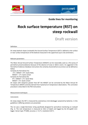
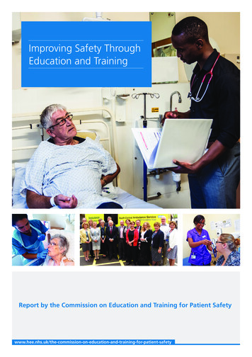
Safety first - Special Edition February 2018Overlooking the airspeed during take-off or conducting a takeoff with an inappropriate speed are directly associated to thefollowing main risks: a lateral or longitudinal runway excursion,maximum brake energy exceedance resulting in a brake fire,tail strike, lack of lateral control once the aircraft is airborne, orobstacle clearance trespassing.This article aims at providing some reminders on the ways thevarious take-off characteristic and limit speeds are elaboratedfrom the certification requirements to the flight test validation,and how they can be implemented in daily operations.We will offer a series of articles on this topic, in the presentand future issues of our magazine, aiming to detail everythingyou always wanted to know about speeds but were afraidto ask. The lines that follow are focusing on the take-off phase.SECURING YOUR TAKE-OFF:UNDERSTANDING SPEEDSCharacteristic speeds are intended to provide reference points that canbe used by pilots as a guide in making judgement in a very dynamicsituation. In this respect, they need close supervision. What speedsexactly should be monitored? What do these speeds mean and wheredo they come from? What happens if such speeds are exceeded?Our objective is to highlight the design and operational considerationsunderlying all recommendations Airbus has issued to flight crews regardingspeed monitoring during take-off.Take-off operating speeds V1, VR and V2 very precisely frame the aircraft takeoff performance limits and the margins that exist in the event of a failure (fig.1).For everyaircraft type, V1,VR and V2 arecomputed byAirbus on the basisof design speedsand evidencecollected during thecertification testingof the airplane.For every aircraft type, V1, VR and V2 are computed by Airbus on the basisof design speeds and evidence collected during the certification testing of theairplane.TAKE-OFF(fig.1)V1: Decision speedVR: Rotation speedV2: Take-off safety speedV1 VR V2005
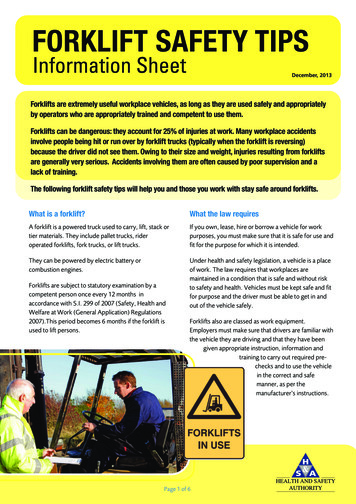
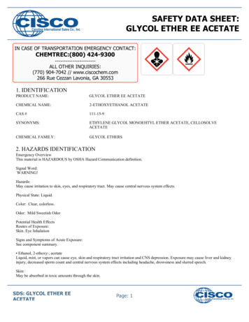
PROCEDURESControl your speed. at take-offV1: Decision speedDefinitionV1 is the maximum speed at which a rejected take-off can be initiated in theevent of an emergency.V1 is also the minimum speed at which a pilot can continue take-off followingan engine failure.This speed is entered by the crew in the MCDU during flight preparation, and it isrepresented by a “1” on the speed scale of the PFD during take-off acceleration(fig.2).How is V1 determined?If take-off is aborted at V1, the aircraft must be able to be stopped before the endof the runway, without exceeding the maximum energy the brakes can absorb.In addition, if an engine failure occurs after V1, then the aircraft must be ableto achieve safely take-off with TOGA or derated power (enough lateral control).These two conditions require identifying: The ground speed at which maximum energy is put into the brakes, whena RTO is performed at MTOW.This limit speed is defined during Airbus flighttests and is called VMBE Maximum Brake Energy speed. V1 must belower than VMBE.(fig.2)V1 on the PFD speed scale
Safety first - Special Edition February 2018 The minimum speed during take-off roll at which the aircraft can still becontrolled after a sudden failure of one engine (be it a two or four-engineairplane).In such a case, and if the take-off is continued, only the rudder will be able tocounteract the yaw moment that is generated by asymmetric engine(s) thrust.Therefore if a failure occurs before reaching this minimum speed, the takeoff must be interrupted to maintain control of the aircraft. This limit speed isdetermined during Airbus flight tests and is called VMCG Minimum Controlspeed on the Ground. VMCG mainly depends on engine(s) thrust and pressurealtitude. V1 must be greater than VMCG. The maximum aircraft speed at which the most critical engine can fail withoutcompromising the safe completion of take-off after failure recognition. Thisdesign speed is called VEF Engine Failure speed.Considering that it is generally assumed humans have a reaction time to anunexpected event (such as a failure) of 1 second, V1 must be greater than VEF.In addition, if an engine failure happens at VEF, then it must be possible tocontinue and achieve safely take-off with TOGA power. This means that VEFmust be greater than VMCG.VMCGVEFWhat are the operational implications of not respecting V1?Supposedly, there are two different ways of “disrespecting” the V1 speed criteria:1. The crew decides to continue take-off while an engine failure occurredbefore V1.Standard procedures encourage the crew to reject take-off if anengine fails before V1. If take-off is continued despite this recommendation, then the aircraft can potentially exit the runway laterally, or be unableto take-off before the end of the runway.BEST PRACTICEIn the event of an engine failure at low speed, any delay in reducing the thrust ofthe good engine(s) will lead to a loss of directional control and a very quick lateraldeviation. Max rudder pedal and max manual differential braking may be required(refer to the new FCTM recommendation AO-020 “Low speed engine failure”).2. An RTO is initiated above V1.Virtually, any take-off can be “successfully” rejected, on the proviso that thereject is initiated early enough and is conducted properly. In this respect, thecrew must always be prepared to make a GO/ NO GO decision prior to theaircraft reaching V1.Doing otherwise exposes the aircraft to an unsafe situation where thereeither may not be enough runway left to successfully stop the aircraft therefore resulting in a longitudinal runway excursion-, or maximum brakeenergy is exceeded and brakes catch fire.V1VMBE007
PROCEDURESControl your speed. at take-offBEST PRACTICEAs speed approaches V1, the successful completion of an RTO becomesincreasingly more difficult. After V1, the crew must continue take-off and considerusing TOGA thrust except if a derated take-off was performed (refer to FCOMPRO-ABN-10 operating techniques).V1 IN A NUTSHELLDo not continue take-offin the event of an engine failure below V1.Do not initiate an RTO at speeds in excess of V1.
Safety first - Special Edition February 2018VR: Rotation speedDefinitionVR is the speed at which rotation can be initiated at the appropriate rate ofabout 3 per second. VR ensures that V2 is reached at 35 feet above therunway surface at the latest, including in the event of an engine failure at VEF.Therefore at 35 feet, the actual speed is usually greater than V2.How is VR determined?In principle, VR shall not be lower than V1.In addition, whenever pilots initiate the rotation at VR, they must be assured thatthe aircraft will be controllable once airborne, including when the most adverseengine has failed after VEF.On the upper end, if the rotation of the aircraft is started at VR at maximumpracticable rate, lift-off must be possible at the end of the maneuver.These concepts involve understanding the following limit speeds: The minimum speed in the second segment (take-off) at which the pilot isstill able to maintain lateral and directional control when the most adverseengine fails.This limit speed is demonstratedby Airbus flight tests and is calledVMCA Minimum Control speed in the Air. VR shall not be lower than1.04 or 1.05 VMCA, the factors 1.04 and 1.05 being defined by AirworthinessAuthorities to ensure a safety margin. The minimum speed at which the aircraft becomes able to lift off and escapeground effect.This limit speed is based on evidence collected during certification tests andis called VMU Minimum Unstick speed. VMU is achieved by pitching theaircraft up to the maximum (tail on the runway, for aircraft that are geometricallylimited) during the take-off roll. The speed at which the aircraft first lifts off isVMU; therefore lift-off is not possible prior to VMU.VMU is different from the design lift-off speed VLOF, which applies to general casescenarios and is necessarily greater than VMU, according to the following criteria:NOTEThe multiplicative factors thatwere applied were specifiedby Airworthiness Authorities, inconsideration of safety margins.1.04 or 1.05 VMU (N-1)1.08 VMU (N)VLOFVLOF009
PROCEDURESControl your speed. at take-offIn turn, VLOF is limited by the design speed VTIRE, which corresponds to themaximum tyre speed
The Airbus safety magazine SPECIAL EDITION Control Your Speed Series. i rst is published by the Product Safety department. It is a source of specialist safety information for the use l y and maintain Airbus aircraft. It is also distributed to other selected organizations and is available on digital devices. Material for publication is obtained from multiple sources and includes selected .