Transcription
PV Grid Tie InverterSolis Single Phase Inverter-US versionInstallation and Operation ManualNingbo Ginlong Technologies Co., Ltd.No. 57 Jintong Road, Binhai Industrial Park,Xiangshan, Ningbo, Zhejiang, 315712, P.R.ChinaTel: 86 (0)574 6578 1806Fax: 86 (0)574 6578 1606Email: info@ginlong.comWeb: www.ginlong.comPlease record the serial number of your inverter and quote this when you contact us.C2014, Ningbo Ginlong Technologies Co., Ltd.Ver 2.5
Contents 31.1 Product Descriptions 31.2 Packaging 4 5 51. Introduction2. Safety Instructions2.1 Safety Symbols 52.3 Notice For Use 6 72.2 General Safety Instructions3. Overview3.1 Front Panel Display 7 7 8 8 9 94.2 Mounting the Inverter 10 11 155.1 Start the Inverter 155.2 Stop the Inverter 153.2 LED Status Indicator Lights3.3 Keypad3.4 LCD4. Installation4.1 Select Location for the Inverter4.3 Electrical Connections5. Start & Stop.1.
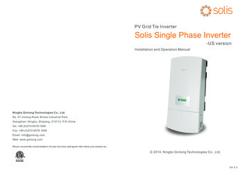
1. IntroductionContents 166.1 Main Menu 166.2 Information 16 18 18 18 196. Operation6.3 Settings6.3.1 Set Time6.3.2 Set Address6.4 Advanced Info.6.4.1 Alarm Message6.4.2 Temperature 19 206.4.3 Standard No. 20 20 20 21 21 22 236.5.4 Calibrate Energy 236.4.4 Version6.4.5 Communication Data6.5 Advanced Settings6.5.1 Select Standard6.5.2 Grid ON/OFF6.5.3 New Password6.6 ARC Fault7. Maintenance8. Trouble Shooting9. Specifications.2.1.1 Product DescriptionsSolis single phase US series inverters can transfer DC power from PV panels into ACpower and feed into grid.Solis single phase US series inverters contain 9 models which are listed below:Solis-1K-2G-US Solis-1.5K-2G-US Solis-2K-2G-US Solis-2.5K-2G-USSolis-3K-2G-US Solis-3.6K-2G-US Solis-4K-2G-US Solis-4.6K-2G-USSolis-5K-2G-USLED lightsLCD display4 buttons 23 24 24 26Water drill holeDC SwitchDC inputRS 485AC inputWiring boxFigure 1.1 Front side viewFigure 1.2 Bottom side view.3.
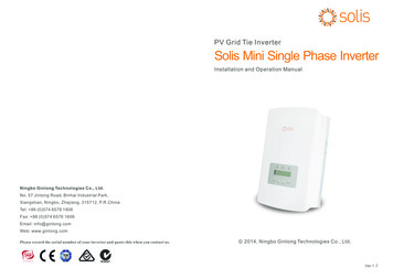
1. Introduction2.Safety Instructions1.2 PackagingImproper use may result in potential electric shock hazards or burns. This manualcontains important instructions that should be followed during installation andWhen you receive the inverter, please check if all the parts listed below are included:maintenance. Please read these instructions carefully before use and keep them forfuture reference.2.1 Safety SymbolsSafety symbols used in this manual, which highlight potential safety risks and importantsafety information, are listed as follows:2WARNING:WARNING symbol indicates important safety instructions, which if notcorrectly followed, could result in serious injury or death.NOTE:3NOTE symbol indicates important safety instructions, which if not correctlyfollowed, could result in some damage or the destruction of the inverter.4CAUTION:1PV Grid Tie InverterSolis Single Phase Inverter-US versionCAUTION, RISK OF ELECTRIC SHOCK symbol indicates important safetyinstructions, which if not correctly followed, could result in electric shock.Installation and Operation ManualCAUTION:CCAUTION, HOT SURFACE symbol indicates safety instructions, which if notcorrectly followed, could result in burns.2014, Ningbo Ginlong Technologies Co., Ltd.Ver 2.35Part NO.12DescriptionWARNING:PV grid tie inverter1Wall mounting bracket1Please don’t connect PV array positive( ) or negative(-) to the ground, it couldcause serious damage to the inverter.3Locking screws24Expansion screws45Manual1Table 1.1 Accessory list.4.2.2 General Safety InstructionsNumberWARNING:Electrical installations must be done in accordance with the local and nationalelectrical safety standards.5.
3. Overview2.Safety InstructionsWARNING:3.1 Front Panel DisplayTo reduce the risk of fire, over-current protective devices (OCPD) arerequired for circuits connected to the Inverter.The DC OCPD should be installed as local requirement. All photovoltaicsource and output circuit conductors shall have disconnects complying withthe NEC, Section 690, Part II. All single phase inverters areintegrate with DCswitch.The trip current for AC OCPD for 1-1.5kW models should be 10A, for 2-2.5kWmodels should be 15A, for 3-3.6kW should be 20A, for 4-5kW should be 25A.CAUTION:Risk of electric shock. Do not remove cover. There is no user serviceableparts inside. Refer servicing to qualified and accredited service technician.CAUTION:The PV array (Solar panels) supplies a DC voltage when it is exposed to light.Figure 3.1 Front Panel DisplayCAUTION:Risk of electric shock from energy stored in capacitors of the Inverter. Do notremove cover until 5 minutes after disconnecting all sources of supply. Servicetechnician only. Warranty may be voided if any unauthorized removal of cover.CAUTION:The surface temperature of the inverter can reach up to 75 (167 F).To avoid risk of burns, do not touch the surface when inverter is operating.Inverter must be installed out the reach of children.2.3 Notice For Use3.2 LED Status Indicator LightsThere are three LED status indicator lights in the front panel of the inverter. Left LED:POWER LED (red) indicates the power status of the inverter. Middle LED: OPERATIONLED (green) indicates the operation status. Right LED: ALARM LED (yellow) indicatesthe alarm status. Please see Table 3.1 for detailsLightDescriptionStatusONThe inverter can detect DC powerOFFNo DC power or low DC powerONThe inverter is operating properly.OFFThe inverter has stopped to supply power.POWERThe inverter has been constructed according to the applicable safety and technicalguidelines. Use the inverter in installations that meet the following sepcification ONLY:1.Permanent installation is required.OPERATIONFLASHING2.The electrical installation must meet all the applicable regulations and standards.3.The inverter must be installed according to the instructions stated in this manual.4.The inverter must be installed according to the correct technical specifications.ALARMThe inverter is initializing.ONAlarm or fault condition is detected.OFFThe inverter is operating properly.5.To startup the inverter, the Grid Supply Main Switch (AC) must be switched on, beforethe solar panel's DC isolator shall be switched on. To stop the inverter, the Grid SupplyTable 3.1 Status Indicator LightsMain Switch (AC) must be switched off before the solar panel's DC isolator shall beswitched off.6.7.
4. Installation3. Overview3.3 Keypad4.1 Select a Location for the InverterThere are four keys in the front panel of the Inverter(from left to right):To select a location for the inverter, the following criteria should be considered:ESC, UP, DOWN and ENTER keys. The keypad is used for:Scrolling through the displayed options (the UP and DOWN keys);Install on a wall or strong structure capable of bearing the weight.Install vertically with a maximum incline of /- 5 .If the mounted inverter is tilted to anangle greater than the maximum noted, heat dissipation can be inhibited, and may resultAccess to modify the adjustable settings (the ESC and ENTER keys).in less than expected output power.The inverter is designed to work in extreme temperatures. The ambient operating3.4 LCDtemperature range is from -25 to 60 .The two-line Liquid Crystal Display (LCD) is located at the front panel of the Inverter,should be kept between each inverter. The bottom of the inverter should be 500mmwhich shows the following information:clearance to the ground.300mmInverter operation status and data;Service messages for operator;300mmIf there is more than 1 inverter installed together, A minimum 300mm clearanceAlarm messages and fault indications.300mm500mm300mm500mm300mmFigure 4.1 Inverter Mounting clearanceVisibility of the LED status indicator lights and the LCD located at the front panel ofthe inverter should be considered.Adequate ventilation must be provided if the inverter is to be installed in a confined space.NOTE:Nothing should be stored on or placed against the inverter.8.9.
4. Installation4.2 Mounting the Inverter4. Installation3. Carefully hang the inverter on the upper part of the wall mount bracket by fitting thehooks into the slot of the bracket. Use M4 25 stainless steel screws and washersPlease use suitable fixings for wall type (e.g. use dynabolts for brick, masonry, etc).at holes E and F (in Figure 4.2) to secure the mounting hooks to the rear of the inverter.InverterABCDE (F)Figure 4.3 Wall Mount BracketFigure 4.2 Inverter MountingInverter should be mounted in a vertical position as shown in Figure 4.2. The steps tomount the inverter on the wall are given as follows:1. Locate the wall studs in the desired location and align the wall mount bracket over4.3 Electrical ConnectionsBefore connection the wire, please unscrew the four screws on both side of wiring box,then open the cover.Please press the cover of wiring box while loose the screw. Otherwise it couldbreak the screw thread.the studs. Mark the mounting holes. For masonry walls, the mounting holes should befor a suitable dynabolt type mounting system.2. MAKE SURE BRACKET IS horizontal. Ensure that the A, B, C, and D mounting holes(in Figure 4.3) are aligned with the wall's most secure points (e.g. wall studs in case ofclad building materials).WARNING:Bracket must be mounted vertically on a vertical wall surface.Figure 4.4 Bottom side of inverter.10.11.
4. Installation4. InstallationBefore electrical connection Please make sure below steps are strictly followed:Connect PV side of inverter:Warninga. Switch the Grid Supply Main Switch (AC) OFF.Before connecting inverter, please make sure the PV array open circuit voltage isb. Switch the DC Switch OFF.within the limit of the inverter. Otherwise the inverter could be damaged. TheTerminal connections:maximum allowable input short circuit current limit of the photovoltaic array for eachMPPT input channel is 10Adc for the 1-3.6kW models and it is 15Adc for the 4-5kWmodels.Please don’t connect PV array positive or negative pole to the ground, it couldcause serious damages to the inverterDC1 DC2 DC1- DC2-L1 L2 NBefore connection, please make sure the polarity of the output voltage of PV arraymatches the“DC ”and “DC-”symbols.Please use qualified DC cable for PV system.Figure 4.5 Connection area of inverter(Fuse type)Note:Damage to the DC Disconnect due to enlarged knockouts.Enlarged knockouts enable moisture to penetrate the DC Disconnect whichcould damage electronic components in the DC Disconnect.Terminal APlease refer figure 4.5 and 4.6 to connect the DC1 and DC2 in the DC terminal of inverter,Terminal Bthen connect the array mounting bonding conductor to two “PE” terminal of DC side. TheDC wire connected to DC terminals (shown in Figure 4.5 and 4.6) is recommendedAWG12-8. For fuse type inverter KLM-20 of Cooper Bussmann or the same type, onlyprofessional can replace it.Connect grid side of inverter:Figure 4.6 Connection area of inverter(Non-Fuse type)Fuse type connection:Strip the end of wire about 10mm, loose the screw on the terminal, then insert the wireinto the terminal. Tight the screws with the torque of 5Nm.Non-Fuse type connection:Strip the end of wire about 18mm. Use a slotted screwdriver, insert to the end of theterminal A and insert the wire into the terminal B. Loose the screwdriver, the cable will befixed in the terminal.12.WARNING:For fuse type: Damage to the inverter through the use of fuses as disconnectingunits in the output circuit of the inverter.The inverter is suitable for 208V and 240V grid. Please see table 4.1 to connect cable toinverter terminals. Due to inverter monitors voltage between L1 and L2, Neutral could beeither connected or not for 240V grid. Ground must be connect to the PE terminal. Thecable for grid connection to AC terminals (“L1”, “L2”, “N” and “PE”) is recommended forAWG 4-8. For fuse type inverter, KLM-30 of Cooper Bussmann or the same type could beused, only professional can replace it.13.
4. Installation5. Start & StopL15.1 Start the InverterL1GRIDSTANDARDTo start up the Inverter, it is important that the following steps are strictly followed:N1. Switch the grid supply main Switch (AC) ON first.2. Switch the DC switch ON. If the voltage of PV arrays are higher than start up voltage,L3L2L2the inverter will turn on. The red LED power will light, and the LCD shows the company'sname and the inverter model.208V 3PH- -3W240V SPLIT-PHASETERMINALL1L2NL1L2NConnection -USFigure 5.1 Company Name and Inverter Model on LCDTable 4.1 Grid terminal connection3. When both the DC and the AC sides supply to the inverter, it will be ready to generateInverter monitoring Connection:power. Initially, the inverter will check both its internal parameters and the parametersThe inverter can be monitored by Wi-Fi or GPRS functions. All the communicationfunctions are optional (Figure 4.6), please refer to communication connectioninstructions.of the AC grid, to ensure that they are within the acceptable limits. At the same time,the green LED will flash and the LCD displays the information of INITIALIZING.4. After 30-300 seconds (depending on local requirement), the inverter will start togenerate power. The green LED will be on continually and the LCD displaysSmart phone monitoringGENERATING.WARNING:Do not touch the surface when the inverter is operating. It may behot and cause burns.GPRS monitoringInternetRouterWeb serverWi-Fi monitoring5.2 Stop the InverterTo stop the Inverter, the following steps must be strictly followed:PC monitoringWi-Fi boxWi-Fi monitoring1. Switch the Supply Main Switch (AC) OFF.2. Wait 30 seconds. Switch the DC Switch OFF. All the LEDs of the inverter will be off in oneminute.Figure4.6 Wi-Fi communication function.14.15.
6. Operation6. OperationDuring normal operation, the display alternately shows the power and the operationstatus with each screen lasting for 10 seconds (see Figure 6.1). Screens can also bescrolled manually by pressing the UP and DOWN keys. Press the ENTER key toaccess to the Main Menu.Pressing theESC keycalls back theprevious menu.Power3424W01-01-2014 12:04DurationV DC1 350.8VI DC15.1A10 secV DC2 350.8VI DC25.1A10 secUP/DOWN orauto-scroll(10 sec)ManufacturerModel nameUP/DOWNPressing theENTER keygives access tothe main menu.V DC1: Shows input 01 voltage value.I DC1: Shows input 01 current value.V DC2: Shows input 02 voltage value.I DC2: Shows input 02 current value.UP/DOWNUP/DOWNV Grid: Shows the grid's voltage valueV Grid 230.4VI Grid8.1A10 secStatus: GeneratingPower: 1488W10 secGrid FrequencyF Grid 60.06Hz10 secF Grid: Shows the grid's frequency value.Total Energy0258458 kwh10 secTotal generated energy valueThis Month: 0123kwhLast Month: 0123kwh10 secToday:15.1kwhYesterday: 13.5kwh10 secAdvanced Info.Status: Generating01-01-2014 12:04DescriptionInformationSettings5 secStartMain MenuDisplayI Grid: Shows the grid's current value.Status: Shows instant status of the Inverter.Power: Shows instant output power value.Advanced settingsFigure 6.1 Operation Overview6.1 Main MenuThere are four submenus in the Main Menu (see Figure 6.1):This Month: Total energy generated this month.Last Month: Total energy generated last month.Today: Total energy generated today.Yesterday: Total energy generated yesterday.1. Information2. SettingsTable 6.1 Information list3. Advanced Info.4. Advanced SettingsPressing the ESC key returns to the Main Menu. Pressing the ENTER key locks(Figure 6.2(a)) or unlocks (Figure 6.2 (b)) the screen.6.2 InformationThe Solis Single Phase Inverter main menu provides access to operational data andinformation. The information is displayed by selecting "Information" from the menuand then by scrolling up or down.5.2 Stop the Inverter(a)(b)Figure 6.2 Locks and Unlocks the Screen of LCD.16.17.
6. Operation6. Operation6.3 Settings6.4 Advanced Info - Technicians OnlyThe following submenus are displayed when the Settings menu is selected:NOTE:To access to this area is for fully qualified and accredited technicians only.Please enter the password to “Advanced Info.” and “Advanced setting”1.Set Time2.Set AddressSelect “Advanced Info.” from the Main Menu. The screen will require the password as below6.3.1 Set TimeYES ENT NO ESC Password:0000This function allows time and date setting. When this function is selected, the LCD willdisplay a screen as shown in Figure 6.3.Figure 6.5 Enter passwordNEXT ENT OK ESC 01-01-2010 16:37Figure 6.3 Set TimePress the UP/DOWN keys to set time and data. Press the ENTER key to move from oneThe default password is “0010". Please press “down” to move the cursor, press “up” toselect the number.After enter the correct password the Main Menu will display a screen and be able to accessto the following information.digit to the next (from left to right). Press the ESC key to save the settings and return to1.Alarm Messagethe previous menu.2.Temperature3.Standard No.4.Version6.3.2 Set Address5.Communication DataThis function is used to set the address when the inverter is connected to the PC. Theaddress number can be assigned from “01”to “99”(see Figure 6.4). The default addressThe screen can be scrolled manually by pressing the UP/DOWN keys. Pressing the ENTERkey gives access to a submenu. Press the ESC key to return to the Main Menu.number of Solis Single Phase Inverter is “01”.YES ENT NO ESC Set Address: 026.4.1 Alarm MessageThe display shows the 10 latest alarm messages (see Figure 6.6). Screens can be scrolledFigure 6.4 Set AddressPress the UP/DOWN keys to set the address. Press the ENTER key to save the settings.Press the ESC key to cancel the change and return to the previous menu.manually by pressing the UP/ DOWN keys. Press the ESC key to return to the previousmenu.Alarm0: OV-G-VTime: 27-11 Data: 7171Figure 6.6 Alarm Message.18.19.
6. Operation6. Operation6.5 Advanced Settings - Technicians Only6.4.2 TemperatureThe screen shows the temperature inside the inverter (see Figure 6.7).Temperature046.6 Figure 6.7 Temperature inside the InverterNOTE:To access to this area is for fully qualified and accredited technicians only.Please follow 6.4 to enter password to access this menu.Select Advanced Settings from the Main Menu to access the following options:1.Select Standard2.Grid ON/OFF3.New Password4.Calibrate Energy6.5.1 Selecting Standard6.4.3 Standard No.The screen shows the reference standard of the Inverter (see Figure 6.8).This function is used to select the grid's reference standard (see Figure 6.11).YES ENT NO ESC Standard:UL-240V-AStandard: UL-240V-AFigure 6.11Figure 6.8 Example of Standard of the InverterNOTE:Before to using this function, please set "GRID OFF" to stop inverter (referto Section 6.5.2).6.4.4 VersionThe screen shows the model version and the software version of the Inverter(see Figure 6.9).Model: 08Software Version: D20001Press the UP/DOWN keys to select the standard (AS4777, VDE4105, VDE0126, UL-240V-A,UL-208V-A, UL-240V, UL-208V, MEX-CFE, G83/2 (for 1-3.6kW models), G59/3 (for 4-5kWmodels), EN50438 DK, EN50438 IE, EN50438 NL and “User-Def” function). Press theENTER key to confirm the setting. Press the ESC key to cancel changes and returns toFigure 6.9 Model Version and Software Version6.4.5 Communication Dataprevious menu.There are 4 settings for USA and CSA market, UL-240V and UL-208V are the settings forinverter without AFCI module, UL-240V-A and UL-208V-A are the settings for inverterThe screen shows the internal data of the Inverter (see Figure 6.10), which is for serviceintegrate with AFCI module.technicians only.01-05: 01 25 E4 9D AA06-10: C2 B5 E4 9D 55Figure 6.10 Communication DataNOTE:The default setting is 240V split phase “UL-240V” or “UL-240V-A”, if it’sdifferent please select 208V single phase “UL-208V” or “UL-208V-A” or220V split phase “MEX-CFE”. Other standards are for 50Hz grid, pleasedon’t select.NOTE:This function is for technicians use only.20.21.
6. Operation6. OperationSelecting the “User-Def” menu will access to the following submenu (see Figure 6.12),OV-V: 262VUN-V: 210V6.5.3 New PasswordThis function is used to set the new password for menu “Advanced info.” and “Advancedinformation” (see Figure 6.14).Figure 6.12YES ENT NO ESC Password: 0000NOTE:The " User-Def" function can be only used by the service engineer andmust be allowed by the local energy supplier.Figure 6.14 Set new passwordEnter the right password before set new password. Press the DOWN key to move theBelow is the setting range for “User-Def”. Using this function, the limits can be changedcursor, Press the UP key to revise the value. Press the ENTER key to execute the setting.manually.Press the ESC key to return to the previous menu.OV-V: 240---270VUN-V: 180---210VOV-G-F: 60.3—62.0Hz(50.3---52.0Hz)UN-G-F: 57.0—59.5Hz(47.0---49.5Hz)6.5.4 Calibrate EnergyMaintenance or replacement could clear or cause a different value of total energy. Use thisfunction could allow user to revise the value of total energy to the same value as before. IfPress the UP/DOWN keys to scroll through items. Press the ENTER key to edit thethe monitoring website is used the data will be synchronous with this setting automatically.highlighted item. Press the UP/DOWN keys again to change the setting. Press the ENTER(see Figure 6.15).key to save the setting. Press the ESC key to cancel changes and returns to the previousYES ENT NO ESC Energy:0000000kWhmenu.NOTE:Please, set "Grid ON" to start up the inverter after the settings (refer toSection 6.5.2). Otherwise the inverter won't start up.Figure 6.15 Calibrate energyPress the DOWN key to move the cursor, Press the UP key to revise the value. Press theENTER key to execute the setting. Press the ESC key to return to the previous menu.6.5.2 Grid ON/OFF6.6 Arc fault(for AFCI version)This function is used to start up or stop the power generation of Solis Single PhaseInverter (see Figure 6.13).6.5.3 Clearing EnergySolis Single Phase Inverter can integrate with AFCI module which can detect the arc in DCcircuit. If arc fault happen, it can only be removed manually.Grid ONGrid OFFDuring start up inverter will check AFCI module. If the check is OK, inverter will startnormally. If the check is fail, LCD will show below:Figure 6.13 Set Grid ON/OFFScreens can be scrolled manually by pressing the UP/DOWN keys. Press the ENTER keyto save the setting. Press the ESC key to return to the previous menu.AFCI Check FailRestart ESC Figure 6.16 AFCI check failPress ESC for 3 seconds, the inverter will restart. If the fault happen again, please turnoff inverter to restart. If the fault still happen, please contact us.22.23.
8. Trouble Shooting6. OperationAlarm MessageDuring normal operation, If arc fault happen in DC circuit, the inverter will stop output andLCDshow below:ARC-FaultRestart ESC Figure 6.17 Arc faultPlease check DC cables and connections to identify the source of possible arcing. Thenpress ESC for 3 seconds, the inverter will restart.7. MaintenanceOver grid voltageUN-G-VUnder grid voltageOV-G-FOver grid frequencyUN-G-FUnder grid frequencyG-IMPHigh grid impedanceNO-GRIDNo grid voltageOV-DCOver DC voltageOV-BUSOver DC bus voltageUN-BUSUnder DC bus voltageGRID-INTF.Solis Single Phase Inverter does not require any regular maintenance. However, cleaningthe dust on heat-sink will help the inverter to dissipate the heat and increase its life time.Initialization system faultOV-TEMOver TemperatureILeak-FAULTCAUTION:Do not touch the inverter's surface when it is operating. Some parts of the invertermay be hot and cause burns. Turn off the inverter (refer to Section 5.2) and wait fora cool-down period before before any maintenance or cleaning operation.Grid interferenceINI-FAULTGROUND-FAULTThe dust can be removed with a soft brush.Failure descriptionOV-G-VGround faultHigh Grid leakage currentRelay-FAULTRelay check faultDCinj-FAULTHigh DC injection currentAFCI Check FAULTARC-FAULTAFCI module self check faultARC detected in DC circuitThe LCD and the LED status indicator lights can be cleaned with a damp cloth if they are tooTable 8.1 Fault message and descriptiondirty to be read.NOTE:If the inverter displays any alarm message as listed in Table 8.1; pleaseturn off the inverter (refer to Section 5.2 to stop your inverter) and wait for 5minutes before restarting it (refer to Section 5.1 to start your inverter). If thefailure persists, please contact your local distributor or the service center.Please keep ready with you the following information before contacting us.NOTE:Never use any solvents, abrasives or corrosive materials to clean the inverter.8. Trouble Shooting1. Serial number of Solis Single Phase Inverter;The inverter is designed in accordance with the most important international grid-tied2. The distributor/dealer of Solis Single Phase Inverter (if available);standards and safety and electromagnetic compatibility requirements. Before delivering to3. Installation date.the customer, the inverter has been subjected to several tests to ensure its optimal operation4. The description of problem (i.e. the alarm message displayed on the LCD and the statusand reliability.of the LED status indicator lights. Other readings obtained from the Information submenuIn case of failure, the LCD screen will display an alarm message. In this case, the inverter(refer to Section 6.2) will also be helpful.);may stop feeding into the grid. The failure descriptions and their corresponding alarmmessages are listed in Table 8.1:5. The PV array configuration (e.g. number of panels, capacity ofpanels, number of strings, etc.);6. Your contact details.24.25.
2.5K-2G-US70 400Vdc2/2208V/240V208V/240V183 228(for208V rated)/211 264(for240V rated)183 228(for208V rated)/211 264(for240V rated)THD 3%THD 3%DC Switch 96.8% 96.8% 97.5%339W*657H*164D mm(13.3W*25.9H*6.5D inch)339W*657H*164D mm(13.3W*25.9H*6.5D inch)339W*657H*172.5D mm(13.3W*25.9H*6.8D 3 F 140 FNEMA 4XCAN/CSAC22.2 N107.1, UL1741, UL1998, UL1699B, FCC part 15, Class B0-100%.26.DC SwitchOptional-13 F 140 FNEMA 4XCAN/CSAC22.2 N107.1, UL1741, UL1998, UL1699B, FCC part 15, Class B0-100%.27.
240V183 228(for208V rated)/211 264(for240V rated)DC SwitchTHD 3%THD 3% 97.5% 97.5%339W*657H*172.5D mm(13.3W*25.9H*6.8D inch)339W*657H*172.5D mm(13.3W*25.9H*6.8D inch)15kg/33.1lb15kg/33.1lbOptionalDC SwitchOptional-13 F 140 F-13 F 140 FNEMA 4XNEMA 4XCAN/CSAC22.2 N107.1, UL1741, UL1998, UL1699B, FCC part 15, Class B0-100%.28.183 228(for208V rated)/211 264(for240V rated)CAN/CSAC22.2 N107.1, UL1741, UL1998, UL1699B, FCC part 15, Class B0-100%.29.
Solis-4K-2G-USSolis-4.6K-2G-US10 18Adc10 18Adc2/(1 and 2)2/(1 and 2)208V/240V208V/240V183 228(for208V rated)/211 264(for240V rated)183 228(for208V rated)/211 264(for240V rated)THD 3%THD 3% 97.8% 97.8%339W*657H*172.5D mm(13.3W*25.9H*6.8D inch)339W*657H*172.5D mm(13.3W*25.9H*6.8D inch)17kg/33.1lbDC SwitchOptionalDC SwitchOptional-13 F 140 F-13 F 140 FNEMA 4XNEMA 4XCAN/CSAC22.2 N107.1, UL1741, UL1998, UL1699B, FCC part 15, Class B0-100%.30.17kg/33.1lbCAN/CSAC22.2 N107.1, UL1741, UL1998, UL1699B, FCC part 15, Class B0-100%.31.
Solis-5K-2G-US10 18Adc2/(1 and 2)208V/240V183 228(for208V rated)/211 264(for240V rated)THD 3% 97.8%339W*657H*172.5D mm(13.3W*25.9H*6.8D inch)17kg/33.1lbDC SwitchOptional-13 F 140 FNEMA 4XCAN/CSAC22.2 N107.1, UL1741, UL1998, UL1699B, FCC part 15, Class B0-100%.32.
PV grid tie inverter 2 Wall mounting bracket 3 Lo cking s rews 4 Expansion screws 1 5 3 2 4 5 Manual Number 1 1 2 4 1 . Installation Inverter should be mounted in a vertical position as shown in Figure 4.2. The steps to mount the inverter on the wall are given as follows: 1. Locate the wall studs in the desired location and align the wall .