Transcription
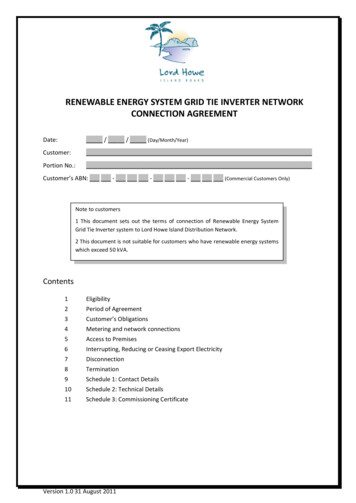
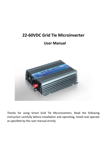
22-60VDC Grid Tie MicroinverterUser ManualThanks for using Smart Grid Tie Microinverters. Read the followinginstruction carefully before installation and operating, install and operateas specified by this user manual strictly.
CatalogueSmart Microinverter Introduction. 1Important Safety Information 2Technical Parameters . . .4Installation . 5-6LED Indicators . . .7-8General troubleshooting .9Stack used method . 10Warranty . .11Product Warranty Card . .12Explore Applications Diagra . . 13
Smart Microinverter IntroductionSmart grid tie inverter is a compact unit, which directly converts directcurrent into alternating current for powering appliances and/or officeequipments and connecting to utility grid. The AC output from SmartMicroinverter is synchronized and in-phase with the utility grid. It is akey device of power generation systems such as PV power generationsystem, wind turbine power generation system. Smart Microinverterspecially optimized design to work with modularization of DC powersupplies which includes the mainstream solar modules, 18V (36 cells),24V (60 cells) and 36V (72 cells) monocrystal and/or Polycrystallinesolar panels, wind turbines and batteries. Smart Microinverters arestabilization, reliable and high conversion efficiency items. It is the bestchoice for PV power generation systems.Smart Microinverter can be easily placed and attached to the rackunderneath of PV module. No need spaces for independent installationand low voltage DC wire connects from the PV module to SmartMicroinverter can eliminate the risk of high DC voltage. Distributedmodularization design philosophy for Smart Microinverter insures theproductiveness of the whole system and will not affect by a single pointof failure. Each Smart Microinverter is individually connected to each PVmodule in the array. This unique configuration means that an individualMaximum Peak Power Point Tracker (MPPT) controls each PV modulesand insures that the maximum power available from each PV module isexported to the utility grid regardless of the performance of the otherPV modules in the array which may be affected by shading, soiling,orientation or mismatch, etc. Smart Microinverter insures topperformance for maximizing energy production from the whole PVsystem and gets return on investment in less time.1/13
Advantages of Smart Microinverter1. Unique circuit design, choice of import industrial electronic components,higher efficiency, more stable performance.2. Creative MPPT technology, efficiency more than 99%, faster and moresensitive reaction, more reliable.3. Parallel type design for DC input and modularization design for inverter,small volume, distributed installation, easy for system configuration,flexible for combination, strong expansibility of system.4. Adopting high-frequency isolation transformer type, high efficiency, andhigh security.5. Perfect electrical protection function.6. Aluminum alloy housing, not rust, heat-resisting and cold-resistant as wellas anti-corrosion.7. Getting electronic circuit design, appearance design and other coretechnology patents.8. Wide input voltage (22-60VDC), suit for different DC power supply.Important Safety InformationRead this FirstThis manual contains important instructions for use during installation andmaintenance of the Smart Microinverter. To reduce the risk of electrical shock,and to ensure the safe installation and operation of the Smart Microinverter, thefollowing safety symbols appear throughout this document to indicate dangerousconditions and important safety instructions.DANGER! This indicates a hazardous situation, which if not avoided,will result in death or serious injury.WARNING! This indicates a situation where failure to follow instructionsmay be a safety hazard or cause equipment malfunction. Use extremecaution and follow instructions carefully.NOTE: This indicates information particularly important for optimalsystem operation.Follow instruction closely.2/13
Safety Instruction Do not use Smart microinverter in a manner not specified by the manufacturer.Doing so may cause death or injury to persons, or damage to equipment.Perform all electrical installations in accordance with all applicable localelectrical codes.Be aware that only qualified personnel should disassemble and repair the SmartMicroinverters and non-qualified personnel should not install and/or repair.Do not attempt to repair the Smart Microinverter; it contains nouser-serviceable parts. If it fails, contact customer service to claim a returnmerchandise authorization and start the replacement process. Tampering withor opening the Smart Microinverter will void the warranty.If the AC cable connector on the microinverter is damaged or broken, do notinstall the unit.Before installing or using the Smart Microinverter, read all instructions andcautionary markings in the technical description and on the Smart MicroinverterSystem and the PV equipment.Connect the Smart Microinverter to the utility grid only after you havecompleted all installation procedures and after receiving prior approval from thelocal electrical utility company.Be aware that the body of the Smart Microinverter is the heat sink. Undernormal operating conditions, the temperature is 15 C above ambient, but underextreme conditions the microinverter can reach a temperature of 65-70 C. Toreduce risk of burns, use caution when working with microinverters.Do NOT disconnect the PV module from the Smart Microinverter without firstremoving AC power when microinverter still working. The better disconnect ACterminal first and then disconnect DC terminal so as it help prevent componentsdamaged and protect the security of the human body.Keep away from children, no touching, no playing so as not to electric shockwhen using.Please installed in place of low humidity and well-ventilated so as to avoidinverter overheating, as well as clear around the inflammable and explosivematerials.3/13
Smart Grid Tie Microinverter Technical Parameters(Suit for 60 cells solar panel which Vmp is 26-30V as well as Voc is 34-38V.)(Suit for 72 cells solar panel which Vmp is 35-37V as well as Voc is 44-46V.)Power500WSolar panels500-600WDC input range22-60VDCMPPT Voltage24-48VDC MAX current45AAC MAX output550WAC output range120VAC(90-140VAC) or 230VAC(190-260VAC)Frequency range50Hz/60Hz(Auto control)Power Factor 97.5%THD 5%Phase Shift 2%Peak Efficiency/110V 85%Stable Efficiency/110V 84%Peak Efficiency/220V 88%Stable Efficiency/220V 86%ProtectionIslanding; Short-circuit; converse connection; Low Voltage;Over Voltage; Over temperature ProtectionWork Temperature-25 -65 Work Humidity0% 90%RH non-condensingGrade of WaterproofIndoor designShowLEDCoolingFanStand-by Power2-3WEMCEN61000-6-3:2007 EN61000-6-1:2007Grid DisturbanceEN 50178 EN 62109-1 VDE0126-1-12Grid DetectionDIN VDE 1026 UL1741CertificateCEMounting dimension16*13CM4/13
Packing SpecificationPacking AccessoryMechanical SizeNet Weight/PCSInner Box (L x W x H)Carton(L x W x H)Microinverter, AC Cord, User Manual(Warranty Card)21 x 16.5 x 5.3CM1.3KGS/PCS31 x 21 x 11.5 CM42 x 31.5 x 35.5 CM, 6pcs/CTN, 8/11KGSInstallation1. Diagrammatize DC input and AC output terminals,2.Attach the Smart Microinverter to the racking or fix onto the wall,3. Properly connect the positive and negative of solar panel and SmartMicroinverter,5/13
4. AC power cable connects with Smart Microinverter and residential powergrid which refers to low voltage civilian single-phase power grid.5. Switch on power grid after check for input and output connections arecorrect and then switch on the Smart Microinverter. At such time, LEDindicator light up from left to right, it is operating for LED indicators checking.Then operation will enter into DC voltage range checking as per referenceline of 4 of section of LED Indicators introduction. After such checking, LEDwill off from right to left one by one, and then in standby operation. WhenDC and AC connect properly, AC LED and AC frequency LED will light upaccordingly. And then Fault red LED off, blue ST LED and Power outputdisplay Red LED light up and flash. It is indicate that inverter is working.When LED flash slowly, it is indicate that MPPT operating. When blue LED6/13
long light and it is indicate that MPPT locking in. At the same time, Poweroutput display red LED indicators start to run from bottom to top as perreference line of 5 of section of LED Indicators introduction.Status Indications of LED1. Red Led1.1 Red FAULT LED indicator lights up under any conditions as listed below:a) Low-voltage protection(DC input voltage lower than 22V Min. inputvoltage of inverters)b) Over-voltage protection(DC input voltage higher than 60V Max. inputvoltage of invertersc) Over-temperature protection (inverters will be shut down for poweroutput when the temperature of body of inverters higher than 60-65 .)And inverter will be automatically restart up when the temperature of7/13
body of the inverter down to 40-50 d) Power grid fault protection (when 110VAC or 220VAC grid power outageand/or trippede) Islanding protection: inverter will be automatically shut down forpower output when disconnect with power grid1.2 Red LOW indicator: DC input voltage lower than 37VDC1.3 Red High indicator: DC input voltage higher than 37VDC1.4 Red Power LED indicator: starting up DC voltage checking and output powerLED status display2. Blue ST LEDa) Blue LED flash: adjusting for power output, MPPT operating for trackingb) Blue LED long light: indicates inverter locking-in Max. output poweroperation status3. Green LEDa) 120VAC/230VAC Indicators: associated LED lights up when run for power gridvoltage detectionb) 50/60Hz Indicators: associated LED lights up when run for frequencydetection4. Start Up DC Voltage Detection Indicator(Power Output Display)a) Within 10-20V DC input voltage range, one LED indicator flashb) Within 20-30V DC input voltage range, two LED indicators flashc) Within 20-30V DC input voltage range, two LED indicators flashd) Within 40-50V DC input voltage range, four LED indicators flashe) Within 50-60V DC input voltage range, five LED indicators flashRemark: LED indicators run from bottom to top and flash, and detectingtime is 10 times, 0.5s/time5. Output Power LED Indicators(Power output display)a) Output power within 10-100W, one LED indicator flashb) Output power within 100-200W, two LED indicators flashc) Output power within 200-300W, three LED indicators flashd) Output power within 300-400W, four LED indicators flashe) Output power within 400-500W, five LED indicators flashRemark: LED indicators run from bottom to top and flash.6. Please note that above operations only run at grid-connected status.8/13
Troubleshooting a non-operating Smart microinverter1. System halted and /or without power outputa) Check if switch of Smart Microinverter is turn on or not,b) Check if the DC connections to Smart Microinverter are correct or not,c) Check if any reverse DC connections for positive or negative or not,d) Check if DC input voltage is within the range of the Smart Microinverter’snot,e)Check if the utility grid voltage and frequency are fit in with the serviceablerange of Smart Microinverte or not,f)g)Check if fuses of DC side are fusing or not,Check if utility grid voltage properly connecting to Smart Microinverters ornot,DC power supply is normal but no power output:Check if utility grid voltage is connecting to Smart Microinverter or not,Check if utility grid voltage is fit in with the serviceable range of SmartMicroinverte or not,Please visual inspection for the LED operation status, red LED will turn offand green LED will flash or run when inverter connecting with DC powersource which input voltage is fit in with the range as specified and powergrid properly. If still no power output when green LED flash or run, probablyinternal components are damaged, in such case, please turn the defectiveinverter back for further analyze.Please visual inspection for the LED operation status, red LED still turn onand green LED without any flash or run when inverter connecting with DCpower source which input voltage is fit in with the range as specified andpower grid properly, probably internal components are damaged, in suchcase, please turn the defective inverter back for further analyze.2.a)b)c)d)9/13
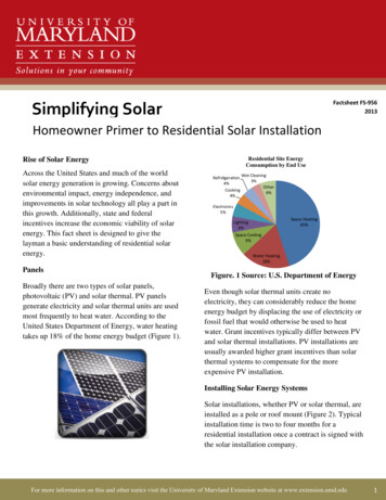
Smart Microinverter Stack Wiring DiagramSmart Microinverter Three Phase output Wiring Diagram10/13
WarrantyWarranty ConditionsWarranty Period: 15-year limited warranty period.Warranty Evidence: The B/L,Tracking no, and a completed warranty card.We Grants from date month year to date month year.If your device has a defect or malfunction during the warranty period, pleasecontact your retailer or installer.Warranty claims are excluded for: Alterations or repairs to the unit without prior authorization Improper use or operation of device Improper and non-standard installation operating the equipment with defective safety devices Impact of foreign objects and force majeure (lightning, surge, storm, fire) Inadequate or nonexistent ventilation of the device disregarding of safety regulations shipping damage The Product has been improperly stored or was damaged while in possessionof the Dealer or end user;WARNING! Only qualified electrical professionals can do the trouble shootingof the Smart Microinverter system.WARNING! Do not disconnect the microinverter from its PV module whenthe inverter is still operating. Disconnect the inverter from the PV moduleduring running may damage the microinverter and bring electrical hazardto the person nearby.WARNING! Disconnect the AC grid first before disconnecting the inverterfrom the PV module.WARNING: Do not attempt to repair the Smart Microinverter. This may bringelectrical hazard to the person and it will also void the Microinverterwarranty. If troubleshooting methods fail, please contact customer support toreturn the Microinverter and initiate for replacement process.11/13
Product Warranty Card(Invalid Duplicate)Customer Feedback:NameCountry and/or TerritoryTelephoneEmailPurchase Channels and/orSourcesModelsDate of PurchaseDate of InstallationTime of UsingBrief Fault DescriptionImprovement SuggestionsDistributor and/or Sales RepresentativeDistributor NameTelephone and/or EmailSales RepresentativeDate of CustomerFeedbackDate of finish DisposalDisposalQCTechnicianOthers12/13
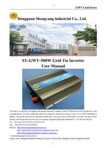
Explore Application Diagram1.Compatible with solar panel as specified in parameter table2.Work with wind turbine,if the wind turbine do not build in wind chargecontroller,need add wind charge controller(24V/36V)3.Work with battery, PV module and wind turbine charging the battery and batterydischarging to inverter for converting AC power which will feed into power grid.13/13
22-60VDC Grid Tie Microinverter User Manual Thanks for using Smart Grid Tie Microinverters. Read the following instruction carefully before installation and operating, install and operate as specified by this user manual strictly. . Smart grid tie inverter is a compact unit, which directly converts direct .