Transcription
2019-10-13 01:061/31ESS Design & installation manualESS Design & installation manual1. ESS Introduction & featuresWhat is ESS?An Energy Storage System (ESS) is a specific type of power system that integrates a power gridconnection with a Victron Inverter/Charger, GX device and battery system. It stores solar energy intoyour battery during the day, for use later on when the sun stops shining.It allows for time shifting power, charging from solar, providing grid support, and exporting powerback to the grid.When an ESS system is able to produce more power than it can use and store, it can sell the surplusto the grid; and when it has insufficient energy or power, it automatically buys it from from the grid.In the ESS system, there must at least be one inverter/charger and also a GX device:Color Control GXVenus GXOther components can be added when needed, see chapter 2.When is it appropriate to use ESS?Use ESS in a self-consumption system; a backup system with solar, or a mixture of both: For exampleyou can use 30% of the battery capacity for self-consumption, and keep the other 70% available as abackup in the event of utility grid failure.Optimizing self-consumption:When there is more PV power than is required to run loads, the excess PV energy is stored in thebattery. That stored energy is then used to power the loads at times when there is a shortage of PVpower.The percentage of battery capacity used for self-consumption is configurable. When utility grid failureis extremely rare it could be set to 100%. In locations where grid failure is common - or even a dailyoccurrence - you might choose to use just 20% of battery capacity and save 80% for the next gridfailure. African countries for example.Keep batteries 100% charged:ESS can also be configured to keep the batteries fully charged. Utility grid failure is then the only timebattery power is used - as a backup. Once the grid is restored, the batteries will be recharged eitherfrom the grid or from solar panels - when available.Victron Energy - https://www.victronenergy.com/live/
Last update: 2019-10-10 10:01ess:design-installation-manual allation-manualESS in a system with a generatorConfiguring ESS in a system which uses a diesel generator as backup - for extended mains failures can be achieved. Grid code and Loss of Mains configuration will need special attention, see here.And on the GX device, select 'Generator' as the AC Input type in the Settings System setup menu.The system will then enable generator charging; ensure that the generator is properly loaded, and willbe automatically switched-off as soon as parameters are met.When not to use ESSOff-grid systems - either with or without generator.Marine systems.Automotive systems.Inverter priority, also known as 'Intentional islanding“ or 'Ignore AC' input systems.With and without grid-meterESS can be used both with an external grid-meter, or without one.Where there is a grid-meter; either a full or partial grid-parallel system can be configured to runalongside.Where there is no grid-meter; all loads are connected to AC-out. And where there is a PV Inverterpresent, that is also connected to AC out.Optional feed-in of MPPT Solar charger powerPower from an MPPT can be fed back to the grid. Enabled/disabled by a user setting on the CCGX:Settings ESS.Fronius Zero feed-in optionBy using the Power Reduction feature in Fronius grid-tie inverters, the ESS system can automaticallyreduce the output of the installed PV Inverters as soon as feed-back is detected; without switchingand frequency shifting.It is not possible to combine ESS with the Fronius Smart Meter - but it's not necessary either, as ESSalready has metering.With ESS, it is not possible to disable feed-in a system with other brands of grid-tie inverters. SeeChapter 2.1.2 for more nted on 2019-10-13 01:06
2019-10-13 01:063/31ESS Design & installation manualESS TrainingESS Webinar 2016-12-19 Youtube (EN)ESS Webinar 2016-12-19 Youtube (DE)ESS Webinar 2016-12-19 Youtube (ES)ESS Webinar 2016-12-19 PPTEnergy Storage System introduction, examples and diagramsA seperate document that provides further introductory information, overviews, and system examplesis available to download here.Advanced control optionsSee ESS mode 2 and 3.1.1 Let's look at the following example-installations:Residential scale Energy Storage System with MPPT Solar ChargerRetrofitting an existing Grid-tie inverter installationSystem with Generator backup (using the auto genset start/stop feature in CCGX)Backup system with SolarAll loads are wired on the AC output of the inverter/charger. The ESS mode is configured to 'Keepbatteries charged'.When using a grid-tie inverter, it is connected to the AC output as well.When grid power is available the battery will be charged with power from both the grid and the PV.Loads are powered from PV when that power-source is available.Feed-in is optional, and can be enabled or disabled depending on local regulations.1.2 ComponentsInverter/chargerThe Energy Storage system, uses a Multi or Quattro bidirectional inverter/charger as its maincomponent.Note that ESS can only be installed on Multis and Quattros which feature the 2nd generationmicroprocessor (26 or 27). All new systems shipped have 2nd generation chips.Victron Energy - https://www.victronenergy.com/live/
Last update: 2019-10-10 10:01ess:design-installation-manual allation-manualGX deviceThe system is managed by the Color Control GX (CCGX), which also provides extensive monitoring,both locally and remotely via our VRM Portal and the VRM App.BatteryVictron Lithium batteries/lithium-battery-24v-180ahThird-party battery compatibilityPlease see this list of third-party batteries with which Victron equipment is ery compatibility:startLead batteries: OPzS and OPzVThe relatively high internal-resistance of these types of batteries should be taken in to account whendesigning a system which uses them.Lead batteries: AGM / GELNote that the use of standard AGM and GEL batteries is not recommended for installations designedto cycle the battery bank every day.Battery MonitorIn most situations, it is not necessary to install a battery monitor:Lithium batteries with canbus connection (BYD B-Box, Pylon, LG Resu and others) already havea built-in battery monitor. Adding another will only set up a conflict. Always use the canbusconnection to provide battery status/state-of-charge data for these batteries.Redflow ZBM / ZCell zinc-bromide flow batteries with the ZCell BMS also support the samecanbus protocol. This is the preferred integration approach for these batteries.The built-in battery monitor of the Multi Inverter/Charger can be used to provide data whereinstalled batteries do not have a monitor built-in. The advantage here is that in an ESS systemthe charge currents from MPPT Solar Chargers will also be taken into account.The only situation where an external battery monitor is required is when a system using a no-monitorbattery type also has additional power sources: for example a DC wind generator. (No monitor batterytypes include lead batteries, for example, or Victron 12.8V lithium batteries.)Where an additional battery monitor is necessary, use one of these:BMV-700Lynx Shunt VE.Canhttps://www.victronenergy.com/live/Printed on 2019-10-13 01:06
2019-10-13 01:065/31ESS Design & installation manualDetailed information is available in the CCGX manual chapter 2.4.Grid Meter (optional)For a full or partial grid-parallel installation an Energy Meter can be installed in the main distributionpanel between the grid and the installation.A grid meter is only required when there is an additional energy source (e.g. PV) connected betweenthe grid and the input side of the Multi/Quattro systems. If all renewable-energy sources areconnected 'downstream' (on the output side) of the inverter/chargers a grid meter will not berequired, but can be added.Click here for more information about the configuration of grid meters.PV (optional)ESS can work with both Grid-tie PV inverters and/or MPPT Solar Chargers. (A mix of both is alsopossible.)When using Grid-tie PV Inverters we recommend monitoring is performed using the CCGX. See CCGXmanual for the options.ESS can also be operated without PV. This is typical for virtual power plants, where the installation ispart of a cluster of small storage systems - supplying energy to the grid during peak demand.2. System design2.1 PV2.1.1 MPPT Solar Charger and/or Grid-tie inverterESS can work with either an MPPT Solar Charger or a grid-tie inverter, and a mix of both.Generally speaking the MPPT Solar Charger will be more effective than a grid-tie inverter in a smallsystem. The reason for this is that an MPPT Solar Charger is up to 99% efficient whereas the PVenergy coming from a grid-tie inverter is first converted from DC to AC, and then back from AC to DC,causing losses up to 20 or 30%. This will be even more noticeable when the energy consumptiontakes place mainly in the mornings and the evenings.When most of the energy consumption takes place during the day - say in an office with airconditioning - a grid-tie inverter will be more efficient. After (very efficient) conversion to AC, the PVenergy is used directly by the air-conditioning unit.In the case of 'no Feed-in' consider using an MPPT Solar Charger - or otherwise a Fronius PV Inverter,and then use the Zero Feed-in function. This will lead to a much more stable system.Victron Energy - https://www.victronenergy.com/live/
Last update: 2019-10-10 10:01ess:design-installation-manual allation-manual2.1.2 Feed-in or no Feed-inThe rules around Feed-in differ all around the world. In various countries:1. Energy can be sold back to the grid- or to reduce the electricity bill by running in reverse.2. Feed-in is allowed, but not rewarded: All energy being fed back is lost in the sense that theutility provider will not pay for you it. It is, however, an ecologically-sound power-contribution.3. Feed-in is absolutely not tolerated - even for a few seconds: there are certain prepaid meters inSouth-Africa that will disconnect from the grid when they detect Feed-in.4. Feeding-in results in inflated bills because the electricity meter can only count in one direction up. Every kWh fed-back to the grid is erroneously counted as energy used, and will be chargedfor.Feed-inFeed-in of PV power via an MPPT Solar Charger can be enabled or disabled in the Energy StorageSystems menu on the CCGX. Note that when disabled, the PV power will still be available to power ACloads.Feed-in of PV connected to grid-tie inverters occurs automatically. There are no settings or specialdesign considerations to be considered whether connected on the input and/or output of theinverter/charger.No feed-inFeed-in of PV power via an MPPT Solar Charger can be enabled or disabled in the Energy StorageSystems menu on the CCGX.For grid-tie inverters, the only option is to use a Fronius grid-tie inverter and use the Fronius ZeroFeed-in function. See chapter 2.1.3.Using other brands of grid-tie inverters in a No-feed-in system is not recommended. With ESS it is notpossible to prevent feed-in where other brands are installed. And using the Hub-2 Assistant as analternative method leads to a less-than-perfect installation. There can be problems with flickeringlights - or even a whole-system shut-down, through overload, when a large load is switched on or off.2.1.3 Fronius Zero Feed-inFor Fronius grid-tie inverters ESS has a special feature: Zero feed-in.With the Zero feed-in option enabled, the ESS system will continuously monitor and actively controlthe output power of the Fronius grid-tie inverter. See chapter 4.3.11 for detailed requirements andsettings.2.1.4 MPPT Solar ChargersAll Victron MPPT solar chargers can be used: both the models with a VE.Direct port as well as themodels with a VE.Can port.https://www.victronenergy.com/live/Printed on 2019-10-13 01:06
2019-10-13 01:067/31ESS Design & installation manual2.1.5 Grid-tie inverter in parallel or on AC out?There are two options when connecting the grid-tie inverter:in parallel with the Multi or Quattro.on the AC out.When connected on the AC out, the factor 1.0 rule must be adhered to. There are no exceptions tothis. Also use the factor 1.0 rule in countries where the utility grid rarely fails; and also whenconnecting a Fronius grid-tie inverter on the AC out, and employing 'Zero feed-in'.2.2 Battery bank capacityIn a grid-parallel system, the size of the battery bank has these effects:Small batteries will be more cost effective: but all available storage capacity is used every daySmall batteries will be charged and discharged with high currents. This will cause lead batteries,in particular, to have a shorter life.Larger batteries, combined with a relatively large PV installation, can store excess power onsunny days. Power might then be available during several consecutive days of poor weather.Larger batteries provide longer autonomy during a power outage. When the installation isrequired to operate as an Uninterrupted power supply a large battery capacity provides securepower provision for longer periods.In a backup system, the battery size is calculated by the required autonomy during a mains failure.See AC-Coupling minimum battery capacity for minimum battery sizes of systems with a grid-tie PVInverter connected on the AC output of the Multi(s) or Quattro(s).2.3 Inverter/charger sizeThe required size of the inverter/charger depends on the type of installation.In a grid-parallel installation, the size of the inverter/charger can be (much?) smaller than the highestexpected nominal and peak loads. For example, to cover the base load of a two-person household, an800VA inverter/charger may be sufficient. For a family, a 3000VA inverter/charger can run mostappliances - as long as not more than one of them is running at the same time. This means that thesystem can reduce grid power consumption from late spring to early autumn - perhaps to zero - withsufficient storage.In a backup installation, the inverter/charger needs to be sized according to the expected loads.2.4 Anti-islandingESS always requires anti-islanding. This is also true for a No feed-in-system.For several countries the built-in anti-islanding in our products can be used. For example the MultiGridin Germany, and the MultiPlus in the United Kingdom. See certificates on our website for details.Victron Energy - https://www.victronenergy.com/live/
Last update: 2019-10-10 10:01ess:design-installation-manual allation-manualIn case there is no certified product available for the country of installation, install external antiislanding.More details here: VEConfigure: grid codes & loss of mains detection.3. InstallationFollow the instructions in the manuals of each component for its correct installation.When installing a single-phase ESS in a system with a three-phase connection to the utility grid, makesure you install the ESS on phase one, L1.Temperature-compensated chargingMulti, MultiPlus, MultiGrid or QuattroConnect the temperature sensor supplied with the device. In the case of installations with multipleunits in parallel, and/or dual- or three-phase configurations, the temperature-sense wire can beconnected to any unit in the system. For more information, see the Parallel and three phase VE.Bussystems.The Multi will, of course, use the measured battery temperature for temperature-compensatedcharging. It will also do this when charging with power coming from a grid-tie PV Inverter whetherconnected to mains, or - in case of a mains failure - with solar power coming from a grid-tie PVInverter when that inverter is connected to the output.Solar chargersSolar chargers will automatically use the information from the Multi or Quattro for temperaturecompensated charging as well. Both VE.Direct Solar chargers and VE.Can Solar chargers.Voltage-sense wiringMulti, MultiPlus, Multi Grid and Quattros: wire the voltage-sense according to the instructions in themanual.VE.Direct solar chargers: there is no voltage-sense option: no voltage sense is used.VE.Can solar chargers: connect a voltage-sense wire to one of the solar chargers in each 'sync' group.4. Configuration4.1 Update to latest firmwareUpdate all components to the latest firmware version:https://www.victronenergy.com/live/Printed on 2019-10-13 01:06
2019-10-13 01:069/31ESS Design & installation manual1. Venus-OS v2.15 or newer. Instructions to upgrade to v2.00 can be found here.2. Multi, MultiGrid, MultiPlus or Quattro to 422 or newer. Instructions here.3. Solar Chargers, either VE.Can or VE.Direct must run their latest firmware version.For firmware files and instructions, see the Firmware section in Victron Professional.4.2 Multi/Quattro and ESS AssistantSettings to be made in VEConfigure:1. Grid tab: configure the country code. A password is required: ask your supplier. Moreinformation in VEConfigure: grid codes & loss of mains detection. Note: If you leave this settingas 'None', the system will not supply battery energy to support local AC loads when the grid isconnected. You do need to change this setting even if it is your intention not to export DCenergy to the grid.2. Add the ESS Assistant. Instructions on how to add an Assistant here.3. General tab: the ESS Assistant will have enabled the built-battery monitor. Leave that enabled(!). Also when there is a BMV or intelligent canbus-connected battery in the system.4. Charger tab: the ESS Assistant will have already selected the proper battery type, as well asdisabled the Storage mode. Verify and where necessary change the rest of the settings: chargevoltages & maximum charge current. Note that, for systems with the ESS Assistant installed,the MPPT Solar Chargers will follow the charge curve as set in VEConfigure. The chargeparameters configured in the MPPT Solar Chargers are ignored in an ESS setup.5. Configure all the other settings.Notes with regards to the Input current-limit and PowerAssist:Input current-limiter setting - The configured limit is used as the threshold for AC current at theAC-in of the Multi/Quattro. Further notice that:Loads in parallel with the Multi/Quattro are not taken into account: therefore, install allloads on the AC-out of the Multi or Quattro in systems that require AC Input Currentlimiter functionality. For example - systems with a small AC load connected.The current limiter will be used for both directions of the current.The PowerAssist setting in VEConfigure3 will be disabled and ignored when ESS isinstalled.The Dynamic current limiter in VEConfigure3 will be disabled and ignored when ESS is installed.Notes relating to Low battery warning levels:The low battery warning is active when the battery voltage drops below the dynamic cut-offlevel plus the restart offset, which defaults to 1.2 Volt for a 48V system. Just like the cut-offvoltage, the warning voltage level is also dynamic.There is no hysteresis: the warning will dissapear when the voltage rises again.During this warning, also called a pre-alarm, the red LED on the Multi will blink, and optionallyCCGX will show a notification. For most ESS systems its recommended to disable thatnotification on the CCGX. See FAQ below.The related parameters on the Inverter tab, ie. the DC input- low shut-down, restart and prealarm levels do not apply. They are ignored when the ESS Assistant is installed.General notes:Victron Energy - https://www.victronenergy.com/live/
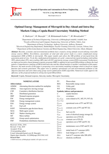
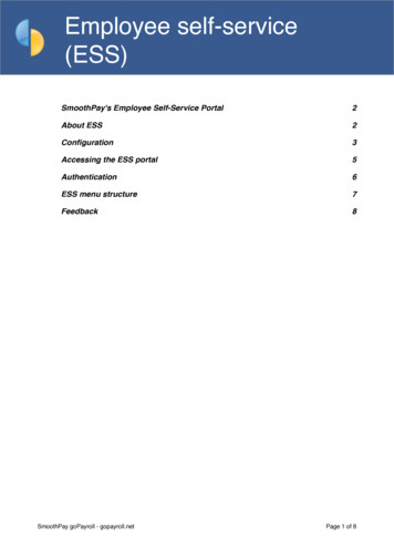
Last update: 2019-10-10 10:01ess:design-installation-manual allation-manualPV power coming from a grid-tie inverter, either connected in parallel on the AC out, will beused to charge the battery. Charge current and other charge parameters are configured on theCharger tab in VEConfigure3.Make sure to keep the lithium batteries checkbox on the charger page consistent with thebattery choice in the Assistant.When using a VE.Bus BMS and a Multi Compact, check the DIP switches: DIP switch 1 must beon, and DIP switch 2 must be off.4.3 GX device - ESS SettingsNavigate to Settings ESS, to see this menu:4.3.1 ModeOptimized (with BatteryLife) and Optimized (without BatteryLife)At times when there is excess PV power, the PV energy is stored in the battery. That stored energy isthen used later, to power the loads at times when there is a shortage of PV power.Keep batteries chargedFailures of the utility grid are the only periods at which the battery will be discharged. Once the grid isrestored, the batteries will be recharged with power from the grid, and of course also solar, whenavailable.External controlhttps://www.victronenergy.com/live/Printed on 2019-10-13 01:06
2019-10-13 01:0611/31ESS Design & installation manualThe ESS control algorithms are disabled. Use this when self-implementing a control loop. Moreinformation.BatteryLifeFor details on BatteryLife operation, see Chapter 6.2. In short, enable BatteryLife for thesetechnologies:OPzV, OPzSGEL / AGMVictron 12.8V Lithium batteries, and other lithium batteries that have passive cell balancingBecause it makes no sense to leave a battery discharged, without reserve power in case of mainsfailure, we recommend leaving BatteryLife enabled on the following battery technologies, too:Lithium with active cell balancingRedflow ZCellHowever, BatteryLife can be disabled in these cases.4.3.2 Grid meter installedLeave Off when no Victron grid meter is installed, and set to 'On' when such meter is installed.All loads and (optional) grid-tie inverters must be installed on the AC out in a system without a Victrongrid meter. See earlier in the manual for more information.4.3.3 Inverter AC output in useSetting this to 'Disabled' hides the AC-out graphic in the overview pane. Use this in systems wherethere is nothing connected to the output of the Multi or Quattro, which is typical for certain gridparallel systems in Western Europe.4.3.4 Feed-in excess solar charger powerSet to 'On' to make the Solar Charger always operates at its maximum power point. The first priorityis powering the loads, and the second priority is to charge the battery. If more power is availablewhen those two priorities are met, then that power will be fed to the utility grid.Please note that when enabling this option, the DVCC charge current limit configured under Settings Limit charge current won't be active. The Solar charger will operate at full power for maximumfeed-in into the grid. It's advisable to configure a safe limit on the solar chargers when used with asmall battery bank.4.3.5 Phase compensationSee see chapter 7.Victron Energy - https://www.victronenergy.com/live/
Last update: 2019-10-10 10:01ess:design-installation-manual allation-manual4.3.6 Minimum Discharge SOC (unless grid fails)Configurable minimum SOC limit. Either with or without BatteryLife enabled, ESS will drop loads oncethe SOC has fallen to the configured setting - except when the utility grid has failed and the system isin Inverter mode. In this case it will continue discharging the battery until one of the other thresholdshave been met. See chapter 6.1 for more information.4.3.7 Actual state of charge limit(Applies only when BatteryLife is enabled)This % shows the maximum usable capacity of the system - which will never be more than 80%.Use this setting to see the current BatteryLife SOC level.4.3.8 BatteryLife stateThe different BatteryLife states are:Self-consumption: normal operation - discharging allowed.Discharge disabled: the battery has been discharged to the actual SOC limit. (The state willreturn to self-consumption whenever the SOC rises 5% above the set limit).Slow charge: ESS will slowly charge the battery when the SOC has been below the actual SOClimit for more than 24 hours. It will keep slow charging until the lower limit has been reached atwhich point the system once again switches to Discharge disabled.Sustain: the Multi/Quattro has gone into sustain mode after the battery voltage has reached thedynamic cut-off voltage during discharge.4.3.9 Limit charge powerThis setting limits the amount of AC power used by the Multi for battery charging. The limit alsoapplies to AC power received by the Multi from a grid-tie PV Inverter.In other words, this setting limits the flow of power from AC to DC.This setting does not reduce the charge power coming from MPPT Solar Chargers.This setting only applies to utilities connected to AC-in: In inverter mode, the 'charge-currentsetting' - as configured in VEConfigure - is used to control power coming from grid-tie PVInverters.4.3.10 Limit inverter powerLimit the power drawn by the Multi: ie. limit the power being inverted from DC to d on 2019-10-13 01:06
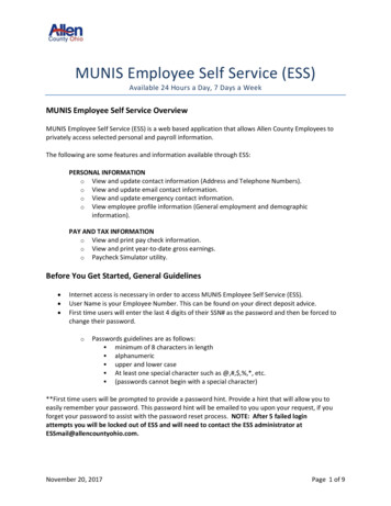
2019-10-13 01:0613/31ESS Design & installation manualThe losses in the inverter/charger are not taken into account. If you want to limit the amount ofpower being drawn from the battery, you will have to set this limit slightly lower to compensatefor those losses.Power coming from the MPPTs is not taken into account. Using this feature in a system withMPPTs can cause the output power from the MPPT to be reduced.This limit is with respect to power drawn from the battery and will affect the total of all phases.This limit only applies while connected to AC-in: In inverter mode, the AC loads determine howmuch power is drawn from the battery.4.3.11 Zero feed-in (Fronius PV inverters only)The earliest Fronius firmware version which can be used is 3.7.3-2If there is more than one Fronius PV Inverter present in the system, they will all be limitedZero feed-in is not supported on Fronius IG Plus inverters.Change the following settings in the Fronius web interface:In the Fronius setup menu, set Data export via Modbus to tcp.In the same menu, set Sunspec Model Type to int SFIn Settings DNO Editor, make sure dynamic power reduction is set to No limit (this is thedefault).Use the Fronius Zero feed-in active menu item to double check that all above criteria are met. It willshow No if the firmware requirement; the Data export; or the Sunspec Model type settings areincorrect.Do not use a Fronius Smart Meter for limiting export when part of a Victron ESS System. More detailsabout when a Fronius Smart Meter can, and can not be used is explained here.4.3.12 Grid setpointThis sets the point at which power is taken from the grid when the installation is in self-consumptionmode. Setting this value slightly above 0W prevents the system from feeding back power to the gridwhen there is a bit of over-shoot in the regulation. The default value is therefore 50W - but should beset to a higher value on large systems.4.4 GX device - Scheduled Charging4.4.1 IntroductionThe Scheduled Charging setting is located in the ESS menu of the GX device. It allows you to set up tofive scheduled periods, during which the system will take power from the grid to charge the battery.This is typically used to charge the battery during off-peak tariff time windows (TOU). For eachschedule, configure a start-time, duration, and optionally set the percentage up to which you want thebattery to be charged.If the target state of charge is reached, and it is still within the period of time set, the battery will stopVictron Energy - https://www.victronenergy.com/live/
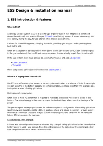
Last update: 2019-10-10 10:01ess:design-installation-manual allation-manualcharging but will not discharge (unless there is grid outage). This optimises battery cycling and stillallows room in the battery for PV charging.4.4.2 ConfigurationScheduled charging is available as part of ESS. It is accessible on the GX device menus under Settings ESS. It is only available when the ESS mode is set to Optimised. Scheduled charging naturallymakes no sense when the mode is set to Keep Batteries Charged.You can see at a glance what is configured, with a summary of the start day, time and duration shownfor each.For each schedule you can select a specific day of the week, every day of the week, or you may opt tocharge on all weekdays or only on weekends.The Multi will start charging from the grid at the specified start time, and stop after the set duration orwhen the set SOC limit is reached. The period designated by the day, start time and duration willsubsequently be referred to as a scheduled charge window.https://www.victronenergy.com/live/Printed on 2019-10-13 01:06
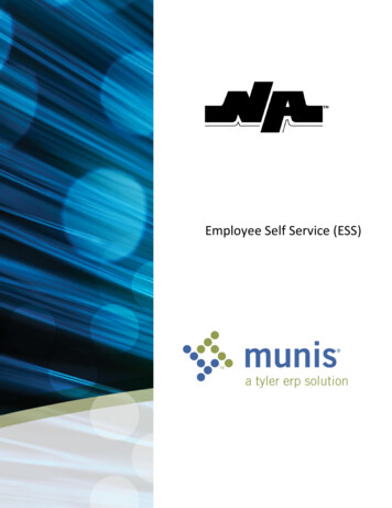
2019-10-13 01:0615/31ESS Design & installation manualDuring charging, the ESS state will ind4.4.3 Stop charge on SOCWhen a SOC limit is set for a scheduled charge window, charging will stop when the batteries reachthe requested SOC. The batteries will however not discharge until the scheduled charge window ends.The goal is to be at or near the requested SOC at the end of the scheduled charge window.4.4.4 Frequently asked questionsWhy does the Multi not discharge the battery after charging ends?Discharge is disabled until the end of the scheduled charge window. The goal is to exit the window atthe requested SOC.How can I prevent discharge to reserve battery capacity for later in the day?Set a charge window for the required period with a low SOC Limit. Discharge is disabled in ascheduled charge window.What happens if I set overlapping schedules?The first matching schedule takes priority. If the two schedules have different SOC limits, the limit ofthe second matching scheduled charge window takes effect after the first scheduled charge windowends.4.5 GX device - Other settingsVictron Energy - https://www.victronenergy.com/live/
Last update: 20
2.1.1 MPPT Solar Charger and/or Grid-tie inverter ESS can work with either an MPPT Solar Charger or a grid-tie inverter, and a mix of both. Generally speaking the MPPT Solar Charger will be more effective than a grid-tie inverter in a small system. The reason for this is that an MPPT Solar Charger is up to 99% efficient whereas the PV


![ESS Design & installation manual [Victron Energy]](/img/34/17369-ess-design-installation-manual-victron-energy.jpg)