Transcription
Electrical Safety in SolidlyGrounded, Resistance Groundedand Ungrounded Power SystemsDetailed Guidelines for Installers, System Designers &Technical Personnel
IntroductionGround Faults in Modern Power SystemsIntroductionHazardous ground faults occur frequently in electrical systems. There are multiple ways to describea ground fault. Some typical definitions are: A leakage current from a conductor to frame or ground measured in milliamperes or amperes An insulation breakdown measured in Ω or kilo-Ω A charging current leaking to ground (capacitive leakage)The 2017 NEC describes a ground fault as an unintentional, electrically conductive connection between anungrounded conductor of an electrical circuit and the normally non-current-carrying conductors, metallicenclosures, metallic raceways, metallic equipment, or earth. Different countries use the term earth faultas it is synonymous with ground fault. Throughout this text, the classic North American terminology willbe used.Why do we have different terms to describe similar occurrences?What amount of current can be expected in a power system?What does the resistor do in a resistance grounded power system?What type of ground-fault monitors does Bender recommend for my system?These question are generated due to the variety of power systems employed. There is a huge variety ofrelays on the market to protect these systems. This booklet has been written to provide a brief introductionto the major power systems and the devices manufactured by Bender which are best suited to protectthese systems in case of a ground fault. The calculations made in the following examples were based onsimple forms assuming test bench or ideal conditions. Values were chosen randomly to support the basicideas and fundamentals. The following information can be used as a guideline for an integrator or as areference for a system designer who is facing the first hurdle of identifying a product for a ground-faultproblem.Detailed information including manuals and datasheets for each product can be found atwww.benderinc.com.This booklet covers the three most common power-system grounding types and their ground-faultprotective devices:Solidly Grounded, Resistance Grounded, and Ungrounded.2
Table of ContentsGeneral InformationTechnology for various power systemsSolidly Grounded SystemsBasic Power SystemsThe Ground FaultGrounded AC systems 60 Hz - The Ground-Fault DeviceGF interrupting - Shunt trip breakerGF interrupting - ContactorGrounded AC systems with VFDsDC SystemsLocating Ground FaultsResistance Grounded SystemsBasic power systemsThe ground faultResistance grounded AC systems- GFGC (Ground Fault Ground Check)- Ground Fault - NGR MonitorLocating ground faultsUngrounded (floating) SystemsBasic power systemsThe ground faultInsulation Monitoring Device IMD- Passive IMD- Active IMDsUngrounded systems- Locating ground faults with portable equipment- Story: Ground fault location in a 480 V delta fed system- Locating ground faults with fixed 5Off-Line MonitoringOff-line monitoring with Bender IR . devices26Index27Products for Solidly and Resistance Grounded Power Systems28-29Products for Ungrounded Electrical Systems30-313
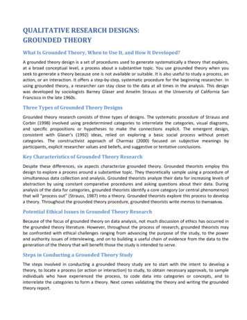
General InformationDetection Technologies for different power system typesNo single type of ground-fault detector works on every type of power system. For instance, a residualcurrent monitor (RCM) ground-fault relay (GFR) in combination with a zero-sequence current transformer(CT) can be used on solidly grounded or resistance grounded systems, but will need very specialconsideration if employed on an ungrounded (floating) system. Similarly, an insulation monitoring device(IMD) can be used on an ungrounded system, but will nuisance trip or false alarm in a grounded system.Case # 1The IMD installation below will not work! The IMD (online megaohmmeter) applies a measuring signal ontoa three-phase ac system. The signal will immediately find the neutral ground bonding jumper and indicatea ground fault. This is equally true for resistance-grounded systems.Supply side 4.16kV:480 / 277 VacL1L2L3circuit breakerLoad: 3 Phase motorL1T1L2T2L3T3BenderIMDNeutral Ground (NG)JumperGNDWRONGapplication!AMP measuring modeFigure 1: A grounded system with an IMD, the wrong part for the jobCase # 2The GFR installation below will not work! The current transformer (CT) in combination with this particularGFR requires a large amount of current to operate. A floating delta cannot create the fault currentmagnitude needed since it does not have a low impedance ground return path, and typically the systemcharging current is lower than the operating point of most GFR’s. The device will never trip, not even if abolted fault (a very low impedance connection between a phase and ground) existed for multiple days.L2NO currentreturn pathL3transformer, passiveLoad: 3 Phase F relayLeakagecapacitanceL1circuit breakerFaul t4.16kV:480 VacGF i.e. dead shortonly mA currentFigure 2: An ungrounded system with RCM technology, another wrong part for a job4
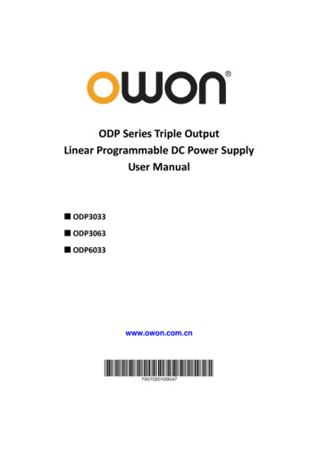
Solidly Grounded SystemsBasic Power Systems - Solidly GroundedSolidly grounded systems have a power source in which the neutral or X0 point of the transformer orgenerator is connected to ground through a solid bonding jumper. This jumper has minimal resistance orimpedance to ground - it does not appreciably limit ground-fault current. Common examples are threephase 208/120-V Wye or 480/277-V Wye configurations, as well as single-phase transformers with thesecondary neutral connected to ground (in rare instances, corner-grounded delta). North Americans arevery familiar with solidly grounded systems as household power typically a split-phase 240/120-V systemwith its neutral bonded solidly to ground. The center tap is bonded solidly to ground.There are advantages and disadvantages to this grounding method. One disadvantage is the largeprospective ground-fault current. Fire, electrical-component damage, or personnel injury can occur.Nevertheless, a tripped overcurrent device (circuit breaker or fuse) or ground-fault circuit-interrupter(GFCI) enables the electrictian to quickly locate the faulted circuit. Corrective action will often takeplace after the fault has occured and the damage is done. Preventative maintenance is not necessarilyassociated with the solidly grounded system.4.16kV:480Vaccircuit breakerLoad: 3 Phase motorL1L1L2L2L3L3VT1V12 480 VV13 480 VT2V23 480 VT3GNDVVNG 0 VV 277 V3GNeutral to GroundBonding JumperFigure 3: A Solidly Grounded Three-Phase System5
Solidly Grounded SystemsThe Ground FaultThe magnitude of ground-fault current in a solidly grounded system can be very large and is dependenton the system voltage and the resistance of the ground-fault current path. This, by NEC definition, is theelectrically conductive path from the point of a ground fault on a wiring system through normally noncurrent-carrying conductors, equipment, or the earth to the electrical supply source. The ground-faultcurrent can easily reach a value that is much higher than the nominal load current. Ground-fault currentis also commonly referred to as residual current and as zero-sequence current. A simplified calculationexplains the high currents:Please review the schematic at the bottom of this page. Fault current IF is defined as:IF IFV3GRGF RGR RNG Fault Current, an amperesV3G Voltage between faulted phase and ground, in voltsRGF Resistance of the ground fault, in ohmsRGR Resistance of the ground-return pathRNG Resistance of neutral-to-ground bonding jumper(Please note: The resistance values are selectively chosen for illustration)IF Power dissipated at the point-of-fault is:P I2 R 692.52 * 0.1 48 kWThis is released as heat.277 V 692.5 A0.1Ω 0.2Ω 0.1ΩThe amount of energy released by the ground fault depends on how long the fault is allowed to persist.It can be shown with this example that fault current can be severe if a dead short occurs. Nevertheless, aground-fault relay or over current protective device should trip very quickly to interrupt power to the load.How much current would flow if a person would create the fault by touching the same circuit? Answer:Replace the dead-short value of 0.1 Ohm with the typicaly resistance of a human body. Assume that aperson is touching the frame of a faulted motor, and is the only path to ground. We will presume 1,000 Ωof resistance for a human body. The calculation for fault current is now:IF 277 V 277 mA1000 Ω 0.2Ω 0.1ΩThe current is several times 15 mA, which is the let-go threshold. 50 mA can be lethal. Overcurrentprotection devices will not trip--a supplemental low-level GFR must be used to guard against this scenario.Supply side 480 / 277 V ACL1L2Neutral to GroundJumper6NG path(resistanceassumed 0.1 Ohm)L3Fault 2 (GF)i.e. dead shor tResistance 0.1Ohmcircuit breakerL1T1L2T2L3T3Motor, 3 p hVFault current p ath via ground(resista nce assumed 0.2 Ohm)GNDV 277 V3GFault 1(break)Figure 4: A 3-phase solidly grounded system with a ground fault and broken ground wire
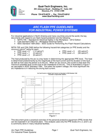
Solidly Grounded SystemsSolidly Grounded AC Systems 60 Hz - The Ground Fault DeviceMost technicians are very familiar with current transformer-based, ground-fault current relays. Nontechnical people also encounter them on a daily basis - GFCI’s protect wall outlets in wet areas such askitchens and restrooms. The operating theory behind the relay is as follows. The power wires leading tothe protected load are passed through a current transformer (CT). It is important that all hot and neutralwires are fed through the CT, and that ground conductors are not. This applies to both, single andthree-phase systems, and CT’s used in this fashion are sometimes referred to as zero-sequence CT’s.Some solidly-grounded three-phase systems do not have a distributed neutral, and may power a pumpor other industrial motor. In this case the three phases only will be fed through the CT. Basic rule forthree-phase systems: If the neutral is carried out to the load, feed it through the CT. If there is no neutral,only the phase conductors pass through the CT window. The CT and ground-fault relay will always readzero current in a healthy system, even under a full-load or overload condition. Assuming that there is noground-fault, incoming and outgoing current through the CT window will cancel each other out, addingto zero. Assume a 10 A load connected to a 480/277 ac system. 10 A will be fed from the source intothe load, therefore 10 A will have to return from the load back to the source. The CT will measure bothsimultaneously, since it is placed around all conductors and measures the sum of the currents carried byall conductors - zero.Σ I1,I2 ,I3 ,.,I x 0Here is what the CT would measure at a specific moment in time. In accordance with the schematicbelow (for a healthy system):10 A 5 A 5 A 0 ASuppose a ground fault (assume IF 1 A) occurs and diverts some of current I3 to the frame, with IFbypassing the CT as IF returns back to the source through the ground-return path. The new equation forthe CT is now:10 A 5 A 4 A 1AWhereas 10 A goes out to the load on L1, 9A return to the source via phases L2 and L3, and 1 A returnsto the source via the ground wire. The sum of currents through the CT is now 1A instead of 0A. The CToutput signal increases, which will cause the GFR to signal an alarm if the measured value (1A) andduration exceeds the GFR’s pickup value and delay time. A GFR in combination with a zero sequenceCT can work in resistance grounded systems as well. Basic GFR devices may have performance issueswhen used on circuits with waveform modifying elements, such as Variable Frequency Drives (VFDs) orrectifier components.4.16kV:480 / 277VacL1L2L3circuit breakerCT passiveLoad: 3 Phase motorL1I1 10 AT1L2I1 5 AT2L3I1 4 AT3Fault 1GNDBenderGF relay (1)withsummationNeutral Ground (NG)Jumper(1) Relays:RCM series, CT: W-SeriesI1 1 AFigure 5:A solidly Grounded System with a Ground-Fault and GF relay7
Solidly Grounded SystemsGround-fault protection – Shunt-trip circuit breakerSome solidly grounded and resistance grounded systems require power interruption when a ground faultoccurs. The ground fault has to be sensed and power has to be removed (often in milli-seconds). Triplevels for ground-fault protection vary depending on the application. In the U.S., Canada, and Mexico,personnel protection on systems up to 240VAC is defined by the standard UL 943 to be 6 mA. Triplevels for equipment protection ranges from 10 mA to multiple amperes. Industrial branch-circuit or loadprotection is often set to 5 A. Service entrance protection is most likely set to trip at levels in hundreds ofAmps. The U.S. NEC and Canadian CEC mandate ground-fault protection on solidly grounded systems,usually at rather high levels, and 6-mA personnel protection for specific circuits. Below is a wiringschematic that shows the connections between a typical Bender RCM-type device, a shunt-trip circuitbreaker, and a three phase load.RCM Terminals: A1, A2 external power supply; k,L CT connection; 11,12 contacts that close andapply 120VAC to the shunt trip coil when ground-fault current through the CT exceeds the RCM set point.The shunt-trip circuit breaker then trips and interrupts power to the load. The circuit breaker must bemanually reset after a trip and after the ground fault is removed or repaired.A1120 VACkBender RCMA2L11RCM12144.16kV:480/277VacL1L2L3Load: 3 Phase motorL1T1L2T2L3T3CTNGRshunt-trip circuit breakerFigure 6: An RCM connected to a shunt-trip circuit breaker in a resistance-grounded system8GND
Solidly Grounded SystemsGround-fault protection - ContactorThe wiring schematic on page 8 employed a shunt-trip circuit breaker. A contactor can accomplish thesame task when upstream overcurrent protection is installed. Please review the schematic below:A1, A2 external power supply; k,L CT connection; 11,14 alarm contacts will open and remove power(120 VAC) from the contactor holding coil (also known as an under-voltage release coil) when groundfault current exceeds the set point. The contactor will drop (open) and interrupt power to the load. Thecontactor can be configured to automatically reset after the fault has been cleared and the RCM groundfault relay is locally or remotely reset.A1120 VACkBender RCM GF relayA2L11RCM1214Load: 3 Phase GRCTGNDFigure 7: An RCM connected to a contactor in a resistance-grounded system9
Solidly Grounded SystemsGrounded AC systems with VFDs60 Hz GFRs have performance limitations when the power system includes Variable Frequency Drives(VFDs). Tests have shown that the typical GFR will not accurately detect a ground fault when the VFDoutput frequency is significantly below 60 Hz. A total inability to detect a ground fault can be expectedat frequencies below 12 Hz. A VFD rectifies the incoming AC voltage to a DC voltage, which is thenmodulated into an adjustable-frequency AC voltage to control the speed of a typical induction motor. ADC ground-fault internal to the VFD cannot be detected using conventional GFR technology, nor cana ground-fault in the motor or cable when the VFD is operating at a low speed. A typical CT can onlydetect AC current and therefore DC fault currents are not detected. Some drives are equipped withtheir own internal scheme to detect ground faults to protect themselves against high-current AC faults.Often drives are manufactured to operate on solidly grounded systems where there is no limitation tothe ground-fault current. The ground-fault current sensitivity of the drive should be checked to determineif it is compatible with resistance-grounded systems and lower-current ground faults. Early warning orpersonnel protection quite likely requires a supplemental GFR.Other issues with VFDs: VFDs often include power quality and EMI filters. Filters and surge protection devices provide leakagepaths to ground and add to the overall system leakage current. Filter components may be rated for line-to-neutral voltage. When installed on an ungrounded orresistance-grounded system, catastrophic component and drive failure can occur during a groundfault. VFDs switch at a kHz carrier frequency. Capacitive reactance decreases as frequency increases,therefore higher frequencies generate higher levels of leakage. Carrier frequencies across insulation,which is a distributed capacitance, adds further to the leakage inherent to the device. Harmonic frequencies that are a result of the switching operations further adds to the impact of theseleakage paths. Transient voltage spikes are a known issue on drives, in particular when the manufacturer’srecommended separation distance between the drive and the motor is exceeded.The solution: VFD’s on grounded systems should be protected with GFR’s capable of detecting AC andDC faults.The Bender NGRM, RCMA, RCMB, and RCMS-series GFM’s, in combination with an activeCT employ a dual winding system, which accurately measures AC, DC, and mixed AC/DC currents. Trip/alarm settings range from 6 mA to 10 A.circuit breakerL1L2L3L1Variable Frequency DriveEMI filterRectifierDC linkInverterL2diodeNeutral to GroundJumperT1T2L3Bender RCMA relay (1)with active CT3 Phase motorPossibleAC fault60 HzCapacitiveleakagethroughEMI filtersSCRInternalDC faultT3GND4.16kV:480/277VacaVriable frequencyAC faults with harmonicsFigure 8: An grounded AC system with a variable-frequency drive & RCMA AC/DC ground-fault protection(1) Relays:10NGRM series, RCMA series, RCMB series, RCMS series.CT’s: CTUB series, W-AB series
Solidly Grounded SystemsDC systemsBender RCMA and RCMB GFR’s monitor DC and mixed AC/DC systems. The unique measuring principlecan be used for protection if the DC system is grounded as shown below. In this example, the negativepole of the DC power supply or battery is connected to the ground. Both the negative and positiveconductors leading to the load are passed through the active-CT window. When a ground fault occurs,DC fault current will flow through ground back to the supply, bypassing the CT. Its magnitude will becalculated by the AC/DC GFM and an alarm will be signaled or the system will trip if so configured. Onekey advantage over voltage-based DC fault detection is that this method can be used to locate a groundfault. It’s important to note that this technology works on AC, DC and mixed AC/DC circuits. For example:A single RCMA relay can protect a DC and an AC system at the same time. Consider a DC control circuitand a 120 VAC power wire going through the same CT. A standard GFR would only monitor the AC line;the RCMA will protect both.circuit breakerActive CT(CTUB series)Load: DC motorI 10 A(L )L I(L-) 9 AVA1F2A2VV(L-G) 0 VBender RCMA relayT2F1V(L G) 125 VL-Faul t(isolation)T1GNDSupply side 125 V DCIF 1 AFigure 9: 125V DC grounded system with RCMA relay and ground-fault11-
Solidly Grounded SystemsLocating ground faults with portable equipmentNormally, it is not too difficult to locate a ground fault in a solidly-grounded system. As describedabove, the ground fault current is usually large and will force the overcurrent device or the groundfault relay to trip the faulty circuit. A ground-fault relay trip can cause unwanted downtime when thereis only a single ground-fault relay, protecting multiple feeders and loads, installed at the power source.A single fault anywhere on that system will cause the power to be disconnected. A typical situation inan industrial plant with a roof-mounted air conditioner that develops a ground fault which trips the mainservice entrance, because no branch-level protection was installed. It is not a simple task to find thefaulted unit when there are 50 other loads on the system. One solution to the problem is shown below:Locating faults in de-energized systems (Offline search)A typical means of checking for a ground fault in a de-energized system uses a megaohmmeter,also known as a hi-pot tester or “Meggering device”. The megaohmmeter is connected across themotor leads and ground (chassis), and applies a high voltage (normally at least 500 V) to the motorcircuit. A ground fault is indicated if the test voltage causes current to flow, which indicates a path toground in the circuit. Note: The megaohmmeter only works on disconnected systems. Make sure that thesystem being tested is locked out from power before applying the megaohmmeter test.4.16kV:480/277VacL1L2L3circuit breakerCB open!Load: 3 Phase motorL1T1L2T2L3T3500 VNeutral to GroundJumperMegaohmeter currentFigure 10: Offline fault location using a Megaohmmeter12Fault 1GND
Solidly Grounded SystemsLocating ground faults with a current clampLocating faults in live systems (Online search)Current-transformer-based ground-fault relays are similar to a sensitive ammeter with a set point. Thetypical clamp-on type ammeter is used to measure load currents by clamping it around a single conductor.The same ammeter will read zero if it is clamped around all conductors (including the neutral, if there isone present) in a healthy system. This is the zero-sequence principle described earlier in the GroundedAC system 60 Hz section on page 7. A healthy system will reveal zero current, but a ground-fault currentwill show up on the clamp. Please note: Do not include the ground conductor when placing the clamparound the power wires. The ground fault can be found by clamping around the conductors coming fromthe power supply first. From there measure individual branch feeders. After the feeder is located, thefault can be further tracked by measuring each load (for example, the circuits from each breaker in adistribution panel can be measured). Proper safety procedures and personal protective equipment mustbe worn when using this method.A typical clamp-type ammeter designed for measuring load currents will work to locate faults if themagnitude of the ground-fault current exceeds a few amperes. A more sensitive ammeter has to beused if the ground fault has a magnitude less than one ampere. Illustration 1 below shows an ammeterwhich is capable of detecting faults below 10 mA. Note the clamp jaw size may limit application on manycircuits. Please be advised that using a clamp meter to find a bolted fault on a solidly grounded system isineffective, as the overcurrent devices will have tripped long before the handheld ammeter can be used.The methods described above will work for ground faults below the trip level of the circuit breakers thatprotect the feeder, which on high-resistance grounded systems is all ground faults. The charging currentfrom unfaulted feeders in the system flow to the ground-fault through system capacitance, which canmake recognizing the actual fault current difficult. A rule of thumb for estimating system charging currentis 1/2 A per 1000 kVA of load for low-voltage systems and 1 A per 1000 kVA for medium-voltage systems.Charging current can also be measured or more-accurately calculated.Effect of Leakage Capacitance: A motor consists of windings, wire and insulation enclosed by a metalframe. The insulation that separates a conductor from ground acts as a small capacitor between thetwo. The insulation also has a certain resistance. The capacitance is usually extremely small and theresistance is in general in the Megohm range. Nevertheless, the leakage current through the combinedpaths can add up. The larger a power system is, the larger the overall natural leakage will be. Imaginea motor in an industrial plant which leaks a minor fraction of current to ground (e.g. 1 mA 1/1000 of anampere). That does not sound like very much and the decision is made to employ a ground-fault relaywith a 10 mA set point. The GFR trips immediately because it was overlooked that there are 15 similarmotors connected to this branch. 15 x 1 mA 15 mA leakage already present in the system. This does noteven account for the capacitive leakage of cabling, surge arrestors, or drive components such as filters.hotneutralIllustration 01: Measuring fault and leakagecurrent with a clamp meter13
Solidly Grounded SystemsLocating Ground Faults in Large Systems using Fixed EquipmentOnline systemAssume that there is a 208-VAC three phase system with 120 branch feeders installed in a facility.Management wants to know at all times if the system is in good condition or if there is a problem.A problem has to be indicated immediately, identified and repaired. The zero-sequence ground-faultmeasuring technology described earlier can help. A permanently installed ground-fault monitoring systemcan monitor an unlimited numbers of circuits 24/7. In this case, a CT will be installed at each feederand branch feeder. The CTs will connect to 12 channel Residual Current Monitoring Systems (RCMS).The RCMS’s can be connected to a central processing system complete with a display unit (CP700).Ground-fault current will flow from the source into the faulty branch, into the faulty load and from thefault back to the source. Zero-sequence CTs in this path will detect the fault current and the RCMS willindicate the channel representing the faulted feeder or load. The central processing unit will display theamount of fault current and the fault location. The faulted circuit can be de-energized if so configured.The ground-fault information can be sent to local indication or externally via communications to PLC’s oreven text messages to mobile devices. Fixed ground fault location systems are tremendously beneficialto maximize uptime and quickly locate and repair faulted equipment.Note that the CTs can measure very low levels of ground-fault current and are designed todetect leaks at an early stage. Fast-developing ground faults, such as a bolted fault on a solidlygrounded system, may trip the overcurrent device before the RCMS will locate the fault. TheRCMS in a solidly grounded system will perform at its best when the fault level is below the branchovercurrent-trip levels. Ground-fault protection is meant to be low level protection and must beco-ordinated with higher-level fault protection.Current transformersfor AC/DC loads (0 2000 Hz)Grounded SystemCurrent transformersfor AC loads (42 2000 Hz)CTUBCTUBCTUBCTUBIllustration 2: Application of RCMS460-D in a multi-branch system14
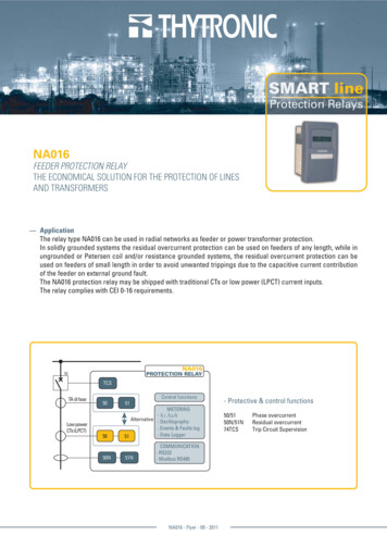
Resistance Grounded SystemsBasic Power Systems - Resistance GroundedA resistance-grounded power system has a fault-current limiting neutral-grounding resistor (NGR)installed between system neutral and ground. Typically these are in three-phase, three-wire (no neutral)wye configured power systems, but sometimes are connected to the “artificial neutral” of a zigzagtransformer. As with ungrounded systems, high-resistance grounded (HRG) systems can be allowedto operate with one phase faulted to ground, and industrial plants where continuity of service is criticaloften use HRG systems. Other facilities, such as in mining, use HRG systems that trip on a groundfault, for maximum safety. A main advantage of the resistance-grounded system is that the resistor limitsthe amount of current available to a ground fault, dramatically reducing point-of-fault damage and theprobability of an arc flash.The Ground FaultGround-fault current in a resistance grounded system is limited in magnitude. This is the main differencewhen compared to the solidly grounded systems discussed earlier. The ground-fault magnitude dependson the NGR rating, and the return-path and ground-fault impedances. Typical HRG and NGR ratings are5, 10, or 25 A. The resistor must be rated for continuous duty use for non-tripping systems and is usually10-s rated on tripping systems.The resistance-grounded system also allows for selective ground-fault tripping which is achieved bymonitoring all feeders and with adjustable time delays on cascaded relays.VLGRGF RGR RNGRIF (3) Fault CurrentIFVLG Voltage between faulted phase and groundRGF Resistance value at point of faultRGR Resistance of ground return pathRNGR Resistance of neutral grounding resistorExample calculation:IF Power dissipated at the point-of-fault is:P I2R 52 *0.1 2.5 W277 V 5A0.1Ω 0.2Ω 55 ΩThe calculation shows that the ground-fault current will not be as devastating as in a solidly groundedsystem if a bolted ground fault occurs. The maximum fault current will be limited, therefore vital machinerycan be kept running until the process is finished. Another approach is to trip on non-critical loads faultsand alarm for those loads that are critical.Supply side 480 / 277 V ACcircuit breakerMotor, 3 p hGT2L3T3dL2unT1roL1L1Ground ReturnResistance 0.2 OhmFigure 11: A resistance grounded system with a ground faultGNDPoint of FaultResistance 0.1 OhmNGRtNeutral grounding path resistanceResistance 55 OhmulL3FaL215
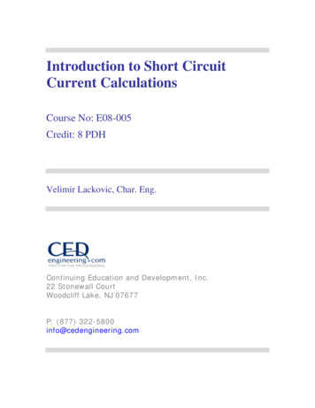
Resistance Grounded SystemsResistance Grounded AC systemsGround Fault Ground CheckAn open-NGR failure leaves a power system ungrounded and therefore without ground-fault detection.Similarly, the failure of the bonding connection to ground at a feeder or piece of equipment leaves aportion of the system without protection. As a result, a hazardous touch voltage can exist. This problemis especially important for mobile or movable loads that rely on the cable ground conductor as the groundreturn path. Ground-check monitors protect against the open-ground-path condition by monitoring thecontinuity of the circuit consisting of a ground-check (pilot) conductor and ground conductor in the cable,terminated at the load by a specialized component that is recognized by the monitor. The ground-checkfault condition is directly related to a ground-fault hazard, therefore the Bender RC48C combines bothGF and GC functions.If ground-fault current exceeds the pickup value, the “Alarm Ground Fault” LED lights and the alarmrelays change state after the selected delay time. The alarm remains latched until
The magnitude of ground-fault current in a solidly grounded system can be very large and is dependent on the system voltage and the resistance of the ground-fault current path. This, by NEC definition, is the electrically conductive path from the point of a ground fault on a wiring system through normally non-