Transcription
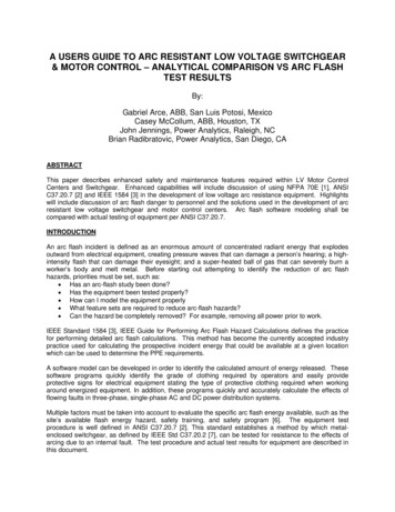
Qual-Tech Engineers, Inc.TheElectricalPowerEngineers201 Johnson Road – Building #1 · Suite 203Houston, PA 15342-1300Phone 724-873-9275 – Fax 724-873-8910www.QualTechEng.comARC FLASH PPE GUIDELINESFOR INDUSTRIAL POWER SYSTEMSFor industrial applications in North America and many countries around the world, the keydocuments with regard to arc flash hazard protection are the following: NFPA 70E – Standard for Electrical Safety in the Workplace – 2012 Edition CSA Standard Z462-12 – Workplace Electrical Safety IEEE Standard 1584-2002 – IEEE Guide for Performing Arc-Flash Hazard CalculationsNFPA 70E and CSA Z462 define the following hazard/risk categories (or PPE levels) and theminimum cal/cm2 rating for each: PPE Level 3(25 cal/cm2) PPE Level 0(1.2 cal/cm2)2 PPE Level 1(4 cal/cm ) PPE Level 4(40 cal/cm2)2 PPE Level 2(8 cal/cm )The heat produced by the arc is a key factor in determining the appropriate PPE level. The heatis determined predominantly by the magnitude of the fault current and the duration of the fault,as well as how near the person is to the arc. When an arc occurs, the current is less than themaximum possible fault current due to the impedance of the arc. This is illustrated in Figure 1as calculated in IEEE Standard 1584. The lower the system voltage, the more significant thearc impedance is in reducing the arcing fault current.Arc Fault Current vs Bolted Fault Current As Calculated In IEEE Standard 1584Grounded or Ungrounded Systems120.00208V System480V System100.00600V System2.4 kV to 13.8 kV SystemsArc Fault Current .0120.0Bolted Fault Current (kA)Figure 1This document gives a practical overview of the personal protective equipment (PPE) levels thatcan be expected in an industrial plant. This analysis uses only the PPE levels of 0, 2, and 4, asis commonly done in many industrial facilities.Arc Flash PPE GuidelinesFor Industrial Power SystemsPage 1Qual-Tech Engineers, Inc.
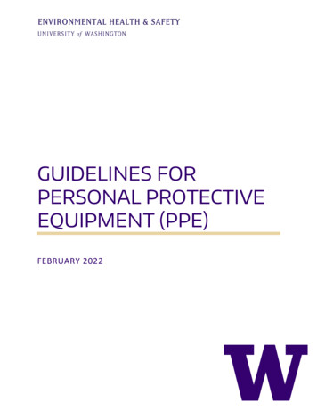
1.012.47 KV TO 13.8 KV SYSTEMSUsing the equations given in IEEE 1584, curves are given which define the maximum clearing timefor a given bolted (or maximum) fault current that would correspond to a PPE level of 2 or 4 for12.47 kV to 13.8 kV systems. A working distance of 36” is used. Figures 2 and 3 illustrate thecalculated limits for metal enclosed switchgear for solidly grounded and impedance groundedsystems respectively.12.47 kV to 13.8 kV PPE RequirementsMaximum Fault Clearing Time vs. Magnitude of the Bolted Fault Current2.0Max. Fault Clearing Time for PPE 2Max. Fault Clearing Time for PPE 41.5Time (Seconds)Calculations are based on IEEE Standard 1584:- 36" Working Distance- Switchgear Equipment Class- Wye-Grounded System1.00.50.00510152025303540Bolted Three-Phase Fault Current (kA)Figure 212.47 kV to 13.8 kV PPE RequirementsMaximum Fault Clearing Time vs. Magnitude of the Bolted Fault Current2.0Max. Fault Clearing Time for PPE 2Max. Fault Clearing Time for PPE 41.5Time (Seconds)Calculations are based on IEEE Standard 1584:- 36" Working Distance- Switchgear Equipment Class- Ungrounded or Impedance Grounded System1.00.50.00510152025303540Bolted Three-Phase Fault Current (kA)Figure 3Arc Flash PPE GuidelinesFor Industrial Power SystemsPage 2Qual-Tech Engineers, Inc.
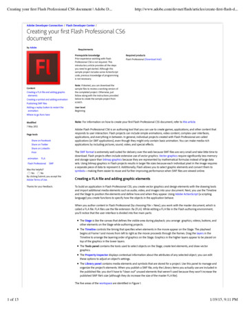
Figures 4 and 5 illustrate the calculated limits for open air switchgear for solidly grounded andimpedance grounded systems, respectively.12.47 kV to 13.8 kV PPE RequirementsMaximum Fault Clearing Time vs. Magnitude of the Bolted Fault Current2.0Max. Fault Clearing Time for PPE 2Max. Fault Clearing Time for PPE 41.5Time (Seconds)Calculations are based on IEEE Standard 1584:- 36" Working Distance- Open Air Class- Wye-Grounded System1.00.50.005101520253035403540Bolted Three-Phase Fault Current (kA)Figure 412.47 kV to 13.8 kV PPE RequirementsMaximum Fault Clearing Time vs. Magnitude of the Bolted Fault Current2.0Max. Fault Clearing Time for PPE 2Max. Fault Clearing Time for PPE 41.5Time (Seconds)Calculations are based on IEEE Standard 1584:- 36" Working Distance- Open Air Class- Ungrounded or Impedance Grounded System1.00.50.0051015202530Bolted Three-Phase Fault Current (kA)Figure 5Arc Flash PPE GuidelinesFor Industrial Power SystemsPage 3Qual-Tech Engineers, Inc.
2.02.4 KV AND 4.16 KV SYSTEMSUsing the equations given in IEEE 1584, curves are given which define the maximum clearing timefor a given bolted (or maximum) fault current that would correspond to a PPE level of 2 or 4 for2.4 kV and 4.16 kV systems. A working distance of 24” is used in Figures 6 and 7 to illustrate thecalculated limits for metal enclosed switchgear for solidly grounded and impedance groundedsystems respectively.2.4 kV & 4.16 kV PPE RequirementsMaximum Fault Clearing Time vs. Magnitude of the Bolted Fault Current2.0Max. Fault Clearing Time for PPE 2Max. Fault Clearing Time for PPE 4Time (Seconds)1.5Calculations are based on IEEE Standard 1584:- 24" Working Distance- Switchgear Equipment Class- Wye-Grounded System1.00.50.00510152025303540Bolted Three-Phase Fault Current (kA)Figure 62.4 kV & 4.16 kV PPE RequirementsMaximum Fault Clearing Time vs. Magnitude of the Bolted Fault Current2.0Max. Fault Clearing Time for PPE 2Max. Fault Clearing Time for PPE 41.5Time (Seconds)Calculations are based on IEEE Standard 1584:- 24" Working Distance- Switchgear Equipment Class- Ungrounded or Impedance Grounded System1.00.50.00510152025303540Bolted Three-Phase Fault Current (kA)Figure 7Arc Flash PPE GuidelinesFor Industrial Power SystemsPage 4Qual-Tech Engineers, Inc.
Figures 8 and 9 illustrate the calculated limits for a working distance of 36” for 2.4 kV and 4.16 kVsystems compared to 24” in Figures 6 and 7.2.4 kV & 4.16 kV PPE RequirementsMaximum Fault Clearing Time vs. Magnitude of the Bolted Fault Current2.0Max. Fault Clearing Time for PPE 2Max. Fault Clearing Time for PPE 4Calculations are based on IEEE Standard 1584:- 36" Working Distance- Switchgear Equipment Class- Wye-grounded SystemTime (Seconds)1.51.00.50.00510152025303540Bolted Three-Phase Fault Current (kA)Figure 82.4 kV & 4.16 kV PPE RequirementsMaximum Fault Clearing Time vs. Magnitude of the Bolted Fault Current2.0Max. Fault Clearing Time for PPE 2Max. Fault Clearing Time for PPE 4Time (Seconds)1.5Calculations are based on IEEE Standard 1584:- 36" Working Distance- Switchgear Equipment Class- Ungrounded or Impedance Grounded System1.00.50.00510152025303540Bolted Three-Phase Fault Current (kA)Figure 9Arc Flash PPE GuidelinesFor Industrial Power SystemsPage 5Qual-Tech Engineers, Inc.
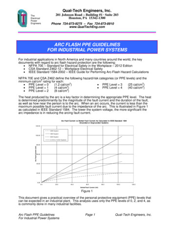
3.0600 VOLT SYSTEMSUsing the equations given in IEEE 1584, curves are given which define the maximum clearingtime for a given bolted (or maximum) fault current that would correspond to a PPE level of 2 or 4for 600 volt systems. A working distance of 18” is used in Figures 10 and 11 to illustrate thecalculated limits for metal enclosed switchgear for solidly grounded and impedance groundedsystems, respectively.600 Volt PPE RequirementsMaximum Fault Clearing Time vs. Magnitude of the Bolted Fault Current2.0Max. Fault Clearing Time for PPE 2Max. Fault Clearing Time for PPE 41.5Time (Seconds)Calculations are based on IEEE Standard 1584:- 18" Working Distance- Switchgear Equipment Class- Wye-Grounded System1.00.50.00102030405060708090100Bolted Three-Phase Fault Current (kA)Figure 10600 Volt PPE RequirementsMaximum Fault Clearing Time vs. Magnitude of the Bolted Fault Current2.0Max. Fault Clearing Time for PPE 2Max. Fault Clearing Time for PPE 41.5Time (Seconds)Calculations are based on IEEE Standard 1584:- 18" Working Distance- Switchgear Equipment Class- Ungrounded or Impedance Grounded System1.00.50.00102030405060708090100Bolted Three-Phase Fault Current (kA)Figure 11Arc Flash PPE GuidelinesFor Industrial Power SystemsPage 6Qual-Tech Engineers, Inc.
4.0480 VOLT SYSTEMSUsing the equations given in IEEE 1584, curves are given which define the maximum clearingtime for a given bolted (or maximum) fault current that would correspond to a PPE level of 2 or 4for 480 volt systems. A working distance of 18” is used in Figures 12 and 13 to illustrate thecalculated limits for metal enclosed switchgear for solidly grounded and impedance groundedsystems, respectively.480 Volt PPE RequirementsMaximum Fault Clearing Time vs. Magnitude of the Bolted Fault Current2.0Max. Fault Clearing Time for PPE 2Max. Fault Clearing Time for PPE 4Time (Seconds)1.5Calculations are based on IEEE Standard 1584:- 18" Working Distance- Switchgear Equipment Class- Wye-Grounded System1.00.50.00102030405060708090100Bolted Three-Phase Fault Current (kA)Figure 12480 Volt PPE RequirementsMaximum Fault Clearing Time vs. Magnitude of the Bolted Fault Current2.0Max. Fault Clearing Time for PPE 2Max. Fault Clearing Time for PPE 41.5Time (Seconds)Calculations are based on IEEE Standard 1584:- 18" Working Distance- Switchgear Equipment Class- Ungrounded or Impedance Grounded System1.00.50.00102030405060708090100Bolted Three-Phase Fault Current (kA)Figure 13Arc Flash PPE GuidelinesFor Industrial Power SystemsPage 7Qual-Tech Engineers, Inc.
5.0208 VOLT SYSTEMSUsing the equations given in IEEE 1584, curves are given which define the maximum clearingtime for a given bolted (or maximum) fault current that would correspond to a PPE level of 2 or 4for 208 volt systems. A working distance of 18” is used in Figures 14 and 15 to illustrate thecalculated limits for metal enclosed switchgear for solidly grounded and impedance groundedsystems, respectively.208 Volt PPE RequirementsMaximum Fault Clearing Time vs. Magnitude of the Bolted Fault Current2.0Max. Fault Clearing Time for PPE 2Max. Fault Clearing Time for PPE 4Time (Seconds)1.5Calculations are based on IEEE Standard 1584:- 18" Working Distance- Switchgear Equipment Class- Wye-Grounded System1.00.50.00102030405060708090100Bolted Three-Phase Fault Current (kA)Figure 14208 Volt PPE RequirementsMaximum Fault Clearing Time vs. Magnitude of the Bolted Fault Current2.0Max. Fault Clearing Time for PPE 2Max. Fault Clearing Time for PPE 4Time (Seconds)1.5Calculations are based on IEEE Standard 1584:- 18" Working Distance- Switchgear Equipment Class- Ungrounded or Impedance Grounded System1.00.50.00102030405060708090100Bolted Three-Phase Fault Current (kA)Figure 15Arc Flash PPE GuidelinesFor Industrial Power SystemsPage 8Qual-Tech Engineers, Inc.
6.0DIFFERENTIAL AND INSTANTANEOUS RELAYS ONMEDIUM VOLTAGE SYSTEMSIn 2.4 kV to 13.8 kV systems the fastest fault clearing times for circuit breakers with conventionalrelays will result from using differential or instantaneous relays. The arcing time of the fault currentin these cases tends to be defined by the following items:Relay Response TimeLockout Relay Response Time (if used)Breaker Opening TimeTotal Time1 to 3 cycles0 to 1 cycle3 to 5 cycles4 to 9 cyclesThe total time could be as fast as 4 cycles and as long as 9 cycles. Using the 9 cycles as a worstcase would give a clearing time of 0.15 seconds for a 60 Hz system. Based on the curves inFigures 2 through 9, it is possible to determine a conservative maximum current that would givea PPE 2 for this voltage range and the 0.15 second clearing time. Some key values aresummarized in Table 1. The key points are noted as follows: For a working distance of 36”, a PPE 2 is possible when using differential andinstantaneous relays for fault currents up to 30 kA for 2.4 to 13.8 kV systems.For a working distance of 24”, a PPE 2 is possible when using differential andinstantaneous relays for fault currents up to 20 kA for 2.4 to 4.16 kV systems.(A working distance of 24” is sometimes appropriate on these lower voltage systems.)With faster clearing times, a PPE 2 can be achieved for higher fault currents.Table 1Maximum Fault Currents to Achieve PPE 2For Medium Voltage SwitchgearSystem kVWorkingDistanceMaximumClearing Time forArcing Current(Seconds)Maximum BoltedFault CurrentTo AchievePPE 2 (kA)SeeFigures12.47 to 13.836"0.15302, 32.4 to 4.1624"36"0.150.1520306, 78, 9Arc Flash PPE GuidelinesFor Industrial Power SystemsPage 9Qual-Tech Engineers, Inc.
7.0LOW VOLTAGE BREAKERSWhen using low voltage breakers, the instantaneous trip on the feeder breakers is typicallyon the order of 0.05 seconds. The main breaker is often set with a delay on the order of0.30 seconds. Based on these typical clearing times, the maximum bolted fault currents areestimated to give PPE 2 and 4 values for low voltage systems in Table 2 based on theinformation given in Figures 10 to 15. For example: The main breaker on a 480V system with an arcing fault clearing time of 0.30 secondscan achieve a PPE 4 for bolted fault currents up to 60 kA for a working distance of 18”.If an instantaneous trip can be used with a clearing time of 0.05 seconds on a 480V system,a PPE 2 can be achieved for bolted fault currents up to 70 kA.Table 2Maximum Fault Currents to Achieve PPE 2 & 4For Low Voltage Circuit BreakersSystem VoltsWorkingDistanceMaximumClearing Time forArcing Current(Seconds)Maximum BoltedFault Current (kA)To Achieve PPEPPESeeFigures60018"0.050.3050402410, 1110, 1148018"0.050.3070602412, 1312, 1320818"0.050.301001002414, 1514, 15Arc Flash PPE GuidelinesFor Industrial Power SystemsPage 10Qual-Tech Engineers, Inc.
8.0TYPICAL PPE LEVELSSeveral examples are given here to illustrate typical PPE levels on industrial power systems due todifferent protection methods. There can be many variations in the parameters which can result insome variation of the PPE levels which are shown here.Example 1Figure 16 illustrates a portion of a typical industrial plant configuration, where the incoming voltageis in the range of 1 to 15 kV. Key observations and characteristics are noted as follows: The overcurrent protection on the medium voltage system is coordinated time overcurrent,but there is no differential protection on the main transformer or main bus.The medium voltage main breaker coordinates with the feeder breaker. The feeder breakerhas an instantaneous trip, but the main breaker does not.A fuse on the primary of the transformer typically does not limit the PPE to 4 on the lowvoltage secondary (i.e. location 5) for transformers of 1500 kVA. For smallertransformers and/or tighter fusing, it is possible to achieve PPE 4 at this location.A fuse on the main low voltage bus typically would not limit the PPE to 4 on the main bus(i.e. location 6).If the conductor length from location 7 to location 8 is quite long, the PPE level at location 8can exceed PPE 2.Small down-line loads may achieve PPE 0 (i.e. location 9).Figure 16Arc Flash PPE GuidelinesFor Industrial Power SystemsPage 11Qual-Tech Engineers, Inc.
Example 2Figure 17 illustrates a portion of a typical industrial plant configuration, where the incoming voltageis in the range of 1 to 15 kV. Compared to Example 1, low voltage breakers are illustrated insteadof low voltage fuses. Key observations and characteristics are noted as follows: A main low voltage breaker can typically achieve PPE 4 at location 6 if on the mainbreaker the short time pickup is 3 and the short time delay is 0.4 seconds.At location 6, typically PPE 2, if on the main breaker the instantaneous pickup is 3;however, this characteristic would not coordinate with the feeder breakers. This settingcould be used as a temporary condition to allow some tasks to be done at this lower PPElevel,At location 7, typically PPE 2, if the feeder breaker is equipped with an instantaneous tripcharacteristic. If it does not have an instantaneous, typically PPE 4.At location 8, typically PPE 2, if the feeder breaker is equipped with an instantaneous tripcharacteristic. If it does not have an instantaneous and location 8 is relatively close tolocation 7, typically PPE 4.Small down-line loads may achieve PPE 0 (i.e. location 9).Figure 17Arc Flash PPE GuidelinesFor Industrial Power SystemsPage 12Qual-Tech Engineers, Inc.
Example 3Figure 18 illustrates a portion of a typical industrial plant configuration, where the incoming voltageis in the range of 1 to 15 kV. Compared to Example 2, differential protection is added to themedium voltage main transformer and the main bus. Key observations and characteristics arenoted as follows: The faster differential protection, typically results in a PPE 2 at locations 1 and 2.Figure 18Arc Flash PPE GuidelinesFor Industrial Power SystemsPage 13Qual-Tech Engineers, Inc.
Example 4Figure 19 illustrates a portion of a typical industrial plant configuration, where the incoming voltageis in the range of 1 to 15 kV. Compared to Example 3, a digital relay is used in the feeder breakerthat has a definite time characteristic with a delay of 0.3 to 0.5 seconds that would result in thebreaker tripping for a fault on the low voltage side of the transformer. Key observations andcharacteristics are noted as follows: The faster feeder relay typically results in a PPE 4 at location 5. However, if multipletransformers are fed from the same medium voltage feeder breaker, power would be lostfor all of these transformers for a three-phase secondary fault on one of the transformers.Figure 19Qual-Tech Engineers, Inc.QT-616-0212Arc Flash PPE GuidelinesFor Industrial Power Systems201 Johnson Road · Building #1 - Suite 203Houston, PA 15342-1300724-873-9275FAX 724-873-8910www.QualTechEng.comPage 14Qual-Tech Engineers, Inc.
calculated limits for metal enclosed switchgear for solidly grounded and impedance grounded systems, respectively. 0.0 0.5 1.0 1.5 2.0 0 1020 3040 5060 7080 90 100 Time (Seconds) Bolted Three-Phase Fault Current (kA) 600 Volt PPE Requirements Maximum Fault Clearing Time vs. Magnitude of the