Transcription
ODP Series Triple OutputLinear Programmable DC Power SupplyUser Manual ODP3033 ODP3063 ODP6033www.owon.com.cn
July 2019 edition V1.2.0Copyright LILLIPUT Company. All rights reserved.The LILLIPUT's products are under the protection of the patent rights, including ones which havealready obtained the patent rights and those which are applied for. The information in this manual willreplace all materials published.The information in this manual was correct at the time of printing. However, LILLIPUT will continue toimprove products and reserves the rights to change specification at any time without notice.is the registered trademark of the LILLIPUT Company.Fujian LILLIPUT Optoelectronics Technology Co., Ltd.No. 19, Heming RoadLantian Industrial Zone, Zhangzhou 363005 P.R. ChinaTel: 86-596-2130430Fax: 86-596-2109272Web: www.owon.com.cnE-mail: info@owon.com.cn
General WarrantyOWON warrants that the product will be free from defects in materials and workmanshipfor a period of 2 years (1 year for accessories) from the date of purchase of the productby the original purchaser from the OWON Company. This warranty only applies to theoriginal purchaser and is not transferable to a third party.If the product proves defective during the warranty period, OWON will either repair thedefective product without charge for parts and labour, or will provide a replacement inexchange for the defective product. Parts, modules and replacement products used byOWON for warranty work may be new or reconditioned like new. All replaced parts,modules and products become the property of OWON.To obtain service under this warranty, the customer must notify OWON of the defectbefore the expiration of the warranty period. Customer shall be responsible forpackaging and shipping the defective product to OWON's designated service centre, acopy of the customer’s proof of purchase is also required.This warranty shall not apply to any defect, failure or damage caused by improper use orimproper or inadequate maintenance and care. OWON shall not be obligated to furnishservice under this warranty a) to repair damage resulting from attempts by personnelother than OWON representatives to install, repair or service the product; b) to repairdamage resulting from improper use or connection to incompatible equipment; c) torepair any damage or malfunction caused by the use of non-OWON supplies; or d) toservice a product that has been modified or integrated with other products when theeffect of such modification or integration increases the time or difficulty of servicing theproduct.Please contact the nearest OWON's Sales and Service Offices for services.For better after-sales service, please visit www.owon.com.cn and register the purchasedproduct online.Excepting the after-sales services provided in this summary or the applicable warranty statements,OWON will not offer any guarantee for maintenance definitely declared or hinted, including but notlimited to the implied guarantee for marketability and special-purpose acceptability. OWON shouldnot take any responsibilities for any indirect, special or consequent damages.
Table of Contents1. General Safety Requirements. 12. Safety Terms and Symbols . 23. Quick Start . 33.1 Front/Rear Panel and User Interface . 33.1.1 Front Panel . 33.1.2 Rear Panel . 53.1.3 User Interface . 5Mode Icons . 6Status Icons . 73.2 General Inspection . 73.3 Power-On Check . 73.4 Output Inspection . 83.4.1 Voltage Output Inspection . 83.4.2 Current Output Inspection . 84. Front Panel Operation. 94.1 Turn On/Off the Channel Output . 94.2 Set the Output Voltage/Current . 94.2.1 Set the Output Voltage . 94.2.2 Set the Output Current . 94.3 Over Voltage/Current Protection .104.3.1 Set O.V.P . 104.3.2 Set O.C.P . 104.4 Programmable Output .114.4.1 Data View . 114.4.2 Output Set . 114.4.3 Data process . 124.4.4 Turn On/Off Programmable Output . 134.5 Save Settings/Auto Record .134.5.1 Save Settings . 134.5.2 Auto Record . 144.5.3 View Record . 144.6 Output mode .154.7 Utility Settings.184.7.1 Language . 184.7.2 Brightness . 184.7.3 Beeper . 184.7.4 Clock . 18i
4.8 System Info .184.8.1 View System Information . 184.8.2 Set as Default. 184.8.3 Update . 194.9 Port Settings .204.9.1 Serial port . 204.9.2 LAN Set . 214.9.3 LCD Test . 214.9.4 Key Test . 215. Troubleshooting . 226. Technical Specifications . 237. Appendix . 257.1 Appendix A: Packaging .257.2 Appendix B: General Care and Cleaning.25ii
1.General Safety Requirements1. General Safety RequirementsBefore use, please read the following safety precautions to avoid any possible bodilyinjury and to prevent this product or any other connected products from damage. Toavoid any contingent danger, ensure this product is only used within the rangesspecified.Only a qualified person should perform internal maintenance.To avoid Fire or Personal Injury: Use Proper Power Cord. Use only the power cord supplied with the product andcertified to use in your country. Product Grounded. This instrument is grounded through the power cord groundingconductor. To avoid electric shock, the grounding conductor must be grounded. Theproduct must be grounded properly before any connection with its input or outputterminals. Check all Terminal Ratings. To avoid fire or shock hazard, check all ratings andmarkings on this product. Refer to the user manual for more information aboutratings before connecting to the instrument. Do not operate without covers. Do not operate the instrument with covers or panelsremoved. Use the Proper Fuse. Use only the specified type and rating fuse for this instrument. Avoid exposed circuit. Be careful when working on exposed circuitry to avoid risk ofelectric shock or other injury. Do not operate if any damage. If you suspect damage to the instrument, have itinspected by qualified service personnel before further use. Use your instrument in a well-ventilated area. Please keep well ventilated andinspect the intake and fan regularly. Do not operate in damp conditions. To avoid short circuiting to the interior of thedevice or electric shock, please do not operate in a humid environment. Do not operate in an explosive atmosphere. To avoid damages to the device orpersonal injuries, it is important to operate the device away from an explosiveatmosphere. Keep product surfaces clean and dry. To avoid the influence of dust or moisture in air,please keep the surface of device clean and dry.1
2.Safety Terms and Symbols2. Safety Terms and SymbolsSafety TermsTerms in this manual (The following terms may appear in this manual):Warning: Warning indicates conditions or practices that could result in injury orloss of life.Caution: Caution indicates the conditions or practices that could result indamage to this product or other property.Terms on the product. The following terms may appear on this product:Danger: Indicates an immediate hazard or injury possibility.Warning: Indicates a possible hazard or injury.Caution: Indicates potential damage to the instrument or other property.Safety SymbolsSymbols on the product. The following symbols may appear on the product:Hazardous VoltageRefer to ManualProtective Earth TerminalChassis GroundPublic Ground2
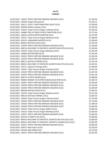
3.Quick Start3. Quick Start3.1 Front/Rear Panel and User Interface3.1.1 Front Panel②①③ ④⑤⑥⑯⑦⑮⑧⑭⑬⑫⑪⑩⑨Figure 3-1 Front panel overview① LCDUser interface display② Numeric keys area Parameter input, includes the numeric keys, decimal point andbackspace key.③ Up and downdirection keySelect sub menu④ Enter keyEnter menu or confirm the parameter entered⑤ KnobSelect menu or change the value, pressing it has the sameeffect as pressing the enter key⑥ Left and rightdirection keySet sub menu or move the cursor⑦ CH3 control areaVolt CH3 key: Set the output voltage of CH3Curr CH3 key: Set the output current of CH3ON/OFF CH3 key: Enable/disable the output of CH33
3.Quick Start⑧ CH2 control areaBlue Volt/CV key: Set the output voltage of CH2Blue Curr/CC key: Set the output current of CH2Blue ON/OFF key: Enable/disable the output of CH2⑨ CH2 outputterminalsChannel 2 output connectors⑩ MODE keySwitch between All Channel mode (CH1 & CH2 & CH3) andDual Channel Mode (CH1 & CH2).⑪ CH1 outputterminalsChannel 1 output connectors⑫ CH3 outputterminalsChannel 3 output connectors⑬ USB Host portConnect as a "host device" with an external USB device, suchas connect a USB disk to the instrument.⑭ Power buttonTurn on/off the instrument⑮ CH1 control areaOrange Volt/CV key: Set the output voltage of CH1Orange Curr/CC key: Set the output current of CH1Orange ON/OFF key: Enable/disable the output of CH1⑯ Function keysUtility key: Menu of output mode, utility, info, port settings.Record key: Save settings, auto record, and view recording.Program key: Programmable output.KeyLock key: Press and hold this key for 5 seconds to lockthe panel keys. Unlock method: Press and hold the key formore than 5 seconds, and release.Instructions for panel key indicatorON/OFF key: The indicator will be lit after you turn on the channel.Volt/CV key: The indicator will be lit when the channel is in Constant Voltage outputmode.Curr/CC key: The indicator will be lit when the channel is in Constant Current outputmode.4
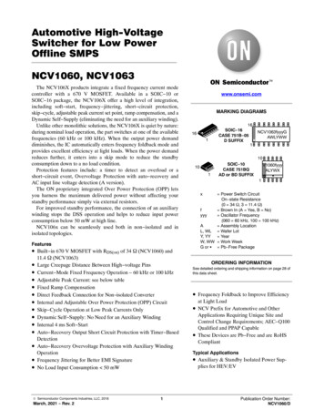
3.Quick Start3.1.2 Rear Panel①②③④⑤⑥Figure 3-2 Rear panel overview① Local AreaNetwork (LAN)ConnectorThe power supply can be connected to the network forremote control via this connector.② USB DeviceConnectorConnect as a "slave device" with an external USB device, suchas connect the instrument to a PC.③ COM ConnectorConnect the power supply with external equipment as serialport.④ Power socketAC input connector⑤ FuseLine fuse⑥ FanFan inlet3.1.3 User InterfaceWhen the output mode is in independent output, or channel tracking mode, there aretwo display modes: All channel mode (CH1 & CH2 & CH3), Dual channel mode (CH1 &CH2). Press the Mode panel key to switch between the modes. All Channel Mode5
3.Quick StartCV: Constant Voltage outputCC: Constant Current outputChannel 2Channel 1Mode iconActual power outputActual voltage outputStatus iconsActual current outputSet values of voltageSet values of currentSet values of O.V.P/O.C.PFigure 3-3 User interface in All channel mode Dual Channel ModeCV: Constant Voltage outputChannel 1CC: Constant Current outputChannel 2Channel 3Mode iconActual power outputActual voltage outputStatus iconsActual current outputSet values of voltageSet values of currentSet values of O.V.P/O.C.PFigure 3-4 User interface in Dual channel modeMode IconsIconsInstructionAll mode, display CH1, CH2 and CH3Dual channel mode, display CH1 & CH2The output mode is parallel trackingThe output mode is series tracking6
3.Quick StartStatus IconsIconsInstructionConnected to the network via LAN connectorConnected as a slave device with PCA USB device is connectedRecording the current outputThe panel keys are lockedThe beeper is turned on3.2 General InspectionWhen you receive your new power supply, it is recommended that you check theinstrument following these steps:1. Check for transportation damage.If it is found that the packaging carton or the foamed plastic protection cushion hassuffered serious damage, do not throw it away until the complete device and itsaccessories have been electrically and mechanically checked.2. Check the AccessoriesThe supplied accessories are described in the "Appendix A: " of this Manual. Pleaseensure that all the listed accessories are present and undamaged, if any problemsare found please contact your distributor or OWON’s local office.3. Check the Complete InstrumentIf there is any physical damage, operational fault, or performance issue pleasecontact your distributor or OWON’s local office. If there is any transportationdamage to the instrument please ensure you keep the original packaging. Ideally youshould always keep the original packaging if the instrument must be returned forrepair.3.3 Power-On Check(1) Connect the instrument to the AC supply using the supplied power cord.Warning:To avoid electric shock, the instrument must be grounded properly.7
3.Quick Start(2) Push the power button on the front panel, the keys will light and the screen willshow the boot screen.3.4 Output InspectionOutput inspection is to ensure that the instrument can achieve its rated outputs andproperly respond to operation from the front panel. For the procedures below, it issuggested that you read "Turn On/Off the Channel Output" on page 9 and "Set the OutputVoltage/Current" on page 9.3.4.1 Voltage Output InspectionThe following steps verify basic voltage functions without load:(1) When the instrument is under no load, select a channel and ensure the outputcurrent setting for this channel is not at zero.(2) Turn on the channel output, then ensure the channel is in Constant Voltage outputmode.(3) Set some different voltage values on this channel; check if the actual voltage valuedisplayed is close to the set voltage value, and also that the actual current valuedisplayed is nearly to zero.(4) Check that if the output voltage can be adjusted from zero to the maximum rating.3.4.2 Current Output InspectionThe following steps check basic current functions with a short across the power supply'soutput:(1) Connect a short across ( ) and (-) output terminals with an insulated test lead on thischannel. Use a wire size sufficient to handle the maximum current.(2) Set the output voltage to the maximum rating on this channel.(3) Turn on the channel output. Ensure the channel you used is in Constant Currentoutput mode.(4) Set some different current values on this channel; check if the actual current valuedisplayed is close to the set current value, and to check if the actual voltage valuedisplayed is nearly zero.(5) Check that if the output current can be adjusted from zero to the maximum rating.(6) Turn off the channel output and remove the short circuit from the output terminals.8
4.Front Panel Operation4. Front Panel Operation4.1 Turn On/Off the Channel OutputPress the orange ON/OFF key to turn on/off the Channel 1 output.Press the blue ON/OFF key to turn on/off the Channel 2 output.Press the ON/OFF CH3 key to turn on/off the Channel 3 output.4.2 Set the Output Voltage/Current4.2.1 Set the Output Voltage Set the output voltage of CH1Press the orange Volt/CV key, the first digit of the CH1 set voltage is flashing,indicating the value is editable. There are two methods to change the value.Modify: Turn the knob to change the value. Press the / key to move thecursor. Press the knob or thekey to confirm.Input: Use the numeric keys to input, the input box of Channel 1 output voltage willpop up. Enter a desired value. Press thekey to confirm. Set the output voltage of CH2Press the blue Volt/CV key to enter edit mode. You can set the value in the same wayas CH1 above. Set the output voltage of CH3Press the Volt CH3 key to enter edit mode. You can set the value in the same way asCH1 above.4.2.2 Set the Output Current Set the output current of CH1Press the orange Curr/CC key, the first digit of the CH1 set current is flashing,indicating the value is editable. There are two methods to change the value.Modify: Turn the knob to change the value. Press the / key to move thecursor. Press the knob or thekey to confirm.Input: Use the numeric keys to input, the input box of Channel 1 output current willpop up. Enter a desired value. Press thekey to confirm. Set the output current of CH29
4.Front Panel OperationPress the blue Curr/CC key to enter edit mode. You can set the value in the same wayas CH1 above. Set the output current of CH3Press the Curr CH3 key to enter edit mode. You can set the value in the same way asCH1 above.Note: If the input value is out of the rated range, the box prompts "ERROR"; you need toinput another value within the rated range.4.3 Over Voltage/Current ProtectionWhen the Over Voltage Protection (O.V.P) or Over Current Protection (O.C.P) is enabled,once the output voltage/current reaches the set value of O.V.P/O.C.P, the instrument willcut off the output, a warning will show on the screen.Note:When the instrument disables the output due to protection, after you make someadjustments, the channel must be restarted to output normally.This function can keep the power output from exceeding the load rating to protect theload.4.3.1 Set O.V.P Set the O.V.P of CH1Press the orange Volt/CV key, the first digit of the CH1 set voltage is flashing. Pressthe key, the first digit of the CH1 O.V.P is flashing, indicating the value is editable.There are two methods to change the value.Modify: Turn the knob to change the value. Press the / key to move thecursor. Press the knob or thekey to confirm.Input: Use the numeric keys to input, the input box of Channel 1 limit voltage willpop up. Enter a desired value. Press thekey to confirm. Set the O.V.P of CH2Press the blue Volt/CV key, then press the key to enter edit mode. You can set thevalue in the same way as CH1 above. Set the O.V.P of CH3Press the Volt CH3 key, then press the key to enter edit mode. You can set thevalue in the same way as CH1 above.4.3.2 Set O.C.P Set the O.C.P of CH110
4.Front Panel OperationPress the orange Curr/CC key, the first digit of the CH1 set current is flashing. Pressthe key, the first digit of the CH1 O.C.P is flashing, indicating the value is editable.There are two methods to change the value.Modify: Turn the knob to change the value. Press the / key to move thecursor. Press the knob or thekey to confirm.Input: Use the numeric keys to input, the input box of Channel 1 limit current willpop up. Enter a desired value. Press thekey to confirm. Set the O.C.P of CH2Press the blue Curr/CC key, then press the key to enter edit mode. You can set thevalue in the same way as CH1 above. Set the O.C.P of CH3Press the Curr CH3 key, then press the key to enter edit mode. You can set thevalue in the same way as CH1 above.4.4 Programmable OutputThe programmable output function can preset up to 100 groups of timing parameters.When you turn on the programmable output, the instrument will output thepre-specified voltage, current in pre-specified time.4.4.1 Data ViewPress the Program key. The Data view menu is selected.(1) The Memory sub menu is selected. Press the / key to select Internal orExternal.(2) Press the key to select Import submenu. Press thekey to import data.(3) Press the key to select Export submenu. Press thekey to export data.Note: When the memory is set as External, the programmable data file will be exportto U disk, the directory is ODPXXXX\Program (ODPXXXX is the model).(4) Press the key to select Clear Data submenu. Press thekey to clear data.4.4.2 Output SetPress the Program key, turn the knob to select [Output Set].(1) The Cycle Mode sub menu is selected. Press the / key to select Oder orLoop.(2) Press the key to select Start Point submenu. Use the numeric keys to input (1 to100), press thekey to confirm.11
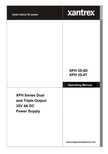
4.Front Panel Operation(3) Press the key to select Stop Point submenu. Use the numeric keys to input (1 to100), press thekey to confirm.(4) Press the key to select Start submenu. Press the / key to select thechannel (CH1, CH2 or ALL), press theand output the selected channel.key to enter the data processing interface4.4.3 Data processYou can set the programmable parameters of CH1 and CH2, including voltage, current andoutput time. This function allows up to 100 parameter groups of each channel.Press the Program key, turn the knob to select [Data process].Edit:(1) The Edit sub menu is selected. The operation instruction shows on the screen. Pressthekey to enter the data processing interface.(2) In the data processing interface, Press the / key to move the cursor left andright. Press the / key to move the cursor up and down. Turn the knob to movethe cursor between CH1 and CH2. Use the After selecting the parameter, use thenumeric keys to enter a desired value, press thekey to confirm.Figure 4-1 Data processing Interface(3) Press to back to sub menu selection.Graph process is used to configure the graphical display in the Data processinginterface.(1) Press the key to select Graph process submenu. Press theediting interface.key to enter the(2) In the Graph processing interface, Press the / key to move the cursor leftand right. Press the / key to move the cursor up and down. Press thekeyto check or uncheck the item. If the item is checked, the corresponding line will be12
4.Front Panel Operationdisplayed in the chart in the data processing interface.(3) Press to back to sub menu selection.4.4.4 Turn On/Off Programmable OutputIn the data processing interface: Independent ModePress orange ON/OFF key to turn on/off the programmable output of Channel 1.Press blue ON/OFF key to turn on/off the programmable output of Channel 2. Parallel/Series ModePress orange ON/OFF key to turn on/off the programmable output.In the data processing interface:Press the key to select Start submenu. Press the / key to select the channel(CH1, CH2 or ALL), press thekey to enter the data processing interface and outputthe selected channel.Note:In the process of programmable output, closing the channel output will reset the timer;turning on the channel again will restart the programmable output and the timer.4.5 Save Settings/Auto Record4.5.1 Save SettingsYou can store, recall and delete current setting parameters. The storage memory could beset as internal or external (USB flash device). Up to 100 groups of settings can be saved.Press the Record key. The Save Settings menu is selected.(1) The Memory sub menu is selected. Press the / key to select Internal orExternal.(2) Press the key to select Save submenu. Press the / key to select thechannel (CH1, CH2 or CH3), press thekey to save the setting of the selectedchannel.Note: When the memory is set as External, the setting will be saved to U disk as aCSV file, the directory is ODPXXXX\Record Option (ODPXXXX is the model).(3) Press the key to select Delete submenu. Press thekey, a red box will showin the table, indicating the selected item. Press the / key to select. Press the / key to turn the page. Press the13key to delete. Press to back to
4.Front Panel Operationsub menu selection.(4) Press the key to select Recall submenu. Press thekey, a red box will show inthe table, indicating the selected item. Press the / key to select. Press the / key to turn the page. Press thekey to recall. Press to back to submenu selection.4.5.2 Auto RecordPress the Record key, turn the knob to select [Auto Record].(1) The Memory sub menu is selected. Press the / key to select Internal orExternal.(2) Press the key to select Interval submenu. Use the numeric keys to set the recordinterval, press thekey to confirm.(3) Press the key to select Points submenu. Use the numeric keys to set the points,press thekey to confirm.(4) Press the key to select Record Status submenu. Press the / key to selectthe channel (CH1, CH2 or CH3), press thethe selected channel. Press thekey to start recording the output ofkey again to stop recording. During recording,the iconwill be lighted on the status bar.Note: When the memory is set as External, the record file will be saved to U disk as aCSV file, the directory is ODPXXXX\Record Auto (ODPXXXX is the model).4.5.3 View RecordPress the Record key, turn the knob to select [View Record].(1) Press the key to select Memory submenu. Press the / key to selectInternal or External.(2) When the Memory is set as Internal, press the key to select Read submenu. Press14
4.Front Panel Operationthe / key to select the channel (CH1, CH2 or CH3), press thekey toread the recording file of the selected channel. After reading successfully, if thedisplay mode is set as Table, a red box will show in the table, indicating you can pressthe / key to turn the page. Press to back to sub menu selection.When the Memory is set as External, press the key to select Export submenu.Press the / key to select the channel (CH1, CH2 or CH3), press thekeyto export the recording
Use Proper Power Cord. Use only the power cord supplied with the andproduct certified to use in your country. Product Grounded. instrument. This is grounded through the power cord grounding conductor. To avoid electric shock, the grounding conductor must be grounded. The product must be grounded properly before any connection with its input or .