Transcription
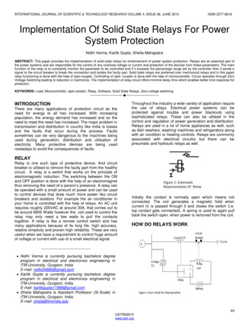
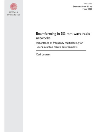
Protection RelaysNA016FEEDER PROTECTION RELAYTHE ECONOMICAL SOLUTION FOR THE PROTECTION OF LINESAND TRANSFORMERS— ApplicationThe relay type NA016 can be used in radial networks as feeder or power transformer protection.In solidly grounded systems the residual overcurrent protection can be used on feeders of any length, while inungrounded or Petersen coil and/or resistance grounded systems, the residual overcurrent protection can beused on feeders of small length in order to avoid unwanted trippings due to the capacitive current contributionof the feeder on external ground fault.The NA016 protection relay may be shipped with traditional CTs or low power (LPCT) current inputs.The relay complies with CEI 0-16 requirements.52TCSTA di faseControl functions5051- Protective & control functions50/5150N/51N74TCS50METERING- I L1.I L3,I EAlternative - Oscillography- Events & Faults log- Data Logger51Low powerCTs (LPCT)50N51NCOMMUNICATION- RS232- Modbus RS485NA016 - Flyer - 09 - 2011Phase overcurrentResidual overcurrentTrip Circuit Supervision
— Measuring inputs— Self diagnosticsThree phase current inputs and one residual current input, withnominal currents independently selectable at 1 A or 5 A (traditional CTs) or three phase currents for low-power CT (LPCT) withselectable rated current.— Output relaysFour output relays are available (two changeover contacts);each relay may be individually programmed as normal state(normally energized or de-energized) and reset mode (manualor automatic).A programmable timer is provided for each relay (minimum pulsewidth). The user may program the function of each relay in accordance with a matrix (tripping matrix) structure.— Binary inputsThree binary inputs are available with predefined functions: IN1 acquisition of 52b auxiliary contact for CB position capture IN2 acquisition of 52a auxiliary contact for CB position capture IN3 Trip circuit Supervision (TCS).All hardware and software functions are repeatedly checkedand any anomalies reported via display messages, communication interfaces, LEDs and output relays.Anomalies may refer to: Hw faults (auxiliary power supply, output relay coil interruptions, .). Sw faults (boot and run time tests for data base, EEPROMmemory checksum failure, data BUS,.).— Firmware updatingThe use of flash memory units allows on-site firmware updating.— Programming and settingsAll relay programming and adjustment operations may be performed through MMI (Keyboard and display) or using a PersonalComputer with the aid of the ThySetter software.The same PC setup software is required to set, monitor and configure all Pro N devices.ThySetter— ConstructionThe NA016 protection relay case is suitable for flush or rackmounting.— MMI (Man Machine Interface)The user interface comprises a membrane keyboard [1], a backlight LCD alphanumeric display and eight LEDs. The green ON LED indicates auxiliary power supply and selfdiagnostics, The yellow LED START, no-latched, indicates Start of the I ,I , I , IE , IE elements The red LED TRIP, no-latched, indicates Trip of the I , I , I ,IE , IE elements The red LED 1, latched, indicates Trip of the I , I , I elements The red LED 2, latched, indicates Trip of the IE , IE elements The red LED 3, no-latched, indicates the 52a state (CB position)[2] The red LED 4, no-latched, indicates the 52a state (CB position))[2] The red LED 5, no-latched, indicates the TCS state[2].Note 1- Keys(CB open ) and(CB close) are disabledNote 2 - Enabled only with Logger option— Data storage[3]Several useful data are stored into a non volatile memory. Sequence of Event RecorderThe event recorder runs continuously capturing in circularmode the last one hundred events upon trigger of binary input/output. Sequence of Fault RecorderThe fault recorder runs continuously capturing in circularmode the last twenty faults upon trigger of binary input/outputand/or element pickup (start-trip). Settings recordingFollowing some setting changes the last ten changes are recorded in circular mode (Data Logger CEI 0-16) Trip countersNote 3 - The data-logger is available according to the CEI 0-16 standard; version with Logger must be requested when ordering.— Communication— MeteringNA016 provides metering values for phase and residual currents,making them available for reading on a display or to communication interfaces.Input signals are sampled 64 times per period and the RMS valueof the fundamental component is measured using the DFT (Discrete Fourier Transform) algorithm and digital filtering.The measured signals can be displayed with reference to nominal values or directly expressed in amperes.Two communication interfaces are implemented: One RS232 local communication front-end interface for communication with ThySetter setup software One RS485 port using ModBus RTU or IEC 60870-5-103 forcommunication with remote monitoring and control systems.— Digital Fault Recorder (Oscillography) [4]Upon trigger of tripping/starting of each function or external signals, the relay records in COMTRADE format: Oscillography with instantaneous values for transient analysis. RMS values for long time periods analysis. Logic states (binary inputs and output relays).Note 4 - A licence for the digital fault recorder function is required.2NA016 - Flyer - 09 - 2011
SPECIF ICAT IONSINPUT CIRCUITSGENERAL— Auxiliary power supply Uaux— Mechanical dataMounting:Mass (flush mounting case)flush, rack1.2 kg— Insulation testsReference standardsHigh voltage test 50HzImpulse voltage withstand (1.2/50 μs)Insulation resistanceEN 60255-52 kV 60 s5 kV 100 MΩ— Voltage dip and interruptionReference standardsEN 61000-4-29— EMC tests for interference immunity1 MHz damped oscillatory waveElectrostatic dischargeFast transient burst (5/50 ns)Conducted radio-frequency fieldsRadiated radio-frequency fieldsHigh energy pulseMagnetic field 50 HzDamped oscillatory waveRing waveConducted common mode (0.150 kHz)EN 60255-22-1EN 60255-22-2EN 60255-22-4EN 60255-22-6EN 60255-4-3EN 61000-4-5EN 61000-4-8EN 61000-4-12EN 61000-4-12EN 61000-4-161 kV-2.5 kV8 kV4 kV10 V10 V/m2 kV1 kA/m2.5 kV2 kV10 V— EmissionReference standardsEN 61000-6-4 (ex EN 50081-2)Conducted emission 0.15.30 MHzClass ARadiated emission 30.1000 MHzClass A— Climatic testsReference standardsIEC 60068-x, ENEL R CLI 01, CEI 50— Mechanical testsReference standardsEN 60255-21-1, 21-2, 21-324.230 Vac/dc19.265 Vac / 19.300 Vdc6 W (9 VA)— Phase current inputsTraditional CTs: Nominal current I n1 A or 5 A selectable by DIP Switches Permanent overload25 A Thermal overload (1 s)500 A Rated consumption (for any phase) 0.002 VA (In 1 A) 0.04 VA (In 5 A) Connections4 mm ring lugs suitable for M4 screwsLow power CTs (according to IEC 60044-8 standard): Nominal primary current I np100 A Extended primary current (selectable via DIP Switches and sw)50.1250 A Maximum primary current12.5 kA Nominal secondary voltage (I pr 100 A)22.5 mV ConnectionsRJ45 plug— Residual current inputNominal current IEnPermanent overloadThermal overload (1s)Rated consumption1 A or 5 A selectable by DIP Switch25 A500 A 0.006 VA (IEn 1 A) 0.012 VA (IEn 5 A)— Binary inputsQuantityTypeMax permissible voltageMax consumption, energized3dry inputs19.265 Vac/19.300 Vdc3 mAOUTPUT CIRCUITS— Output relays K1.K4— Safety requirementsReference standardsPollution degreeReference voltageOvervoltagePulse voltageReference standardsProtection degree: Front side Rear side, connection terminalsEN 61010-13250 VIII5 kVEN 60529IP52IP20— Environmental conditionsAmbient temperatureStorage temperatureRelative humidityAtmospheric pressure-25. 70 C-40. 85 C10.95 %70.110 kPa— CertificationsProduct standard for measuring relaysCE conformity EMC Directive Low Voltage DirectiveType testsEN 502632004/108/EC2006/95/ECIEC 60255-6COMMUNICATION INTERFACESLocal PC RS232RS485 portProtocolNominal value (range)Operative rangePower consumption (max)19200 bps1200.57600 bpsModBus RTU/IEC 60870-5-103Quantity4Command relays K1, K2Type of contactschangeover (SPDT, type C)Nominal current8ANominal voltage/max switching voltage250 Vac/400 VacBreaking capacity:50 W Direct current (L/R 40 ms)1250 VA Alternating current (λ 0,4)Make1000 W/VAShort duration current (0,5 s)30 ASignalling relays K3, K4Type of contactschangeover (SPDT, type C)Nominal current8ANominal voltage/max switching voltage250 Vac/400 Vac— LEDsQuantity ON/fail (green) Start (yellow) Trip (red) Trip I , I , I (red) Trip IE , IE (red) 52a - CB position (red) [1] 52b - CB position (red) [1] TCS - Trip Circuit Supervision (red) [1]811111111Note 1 - Available for versions with data-logger only.NA016 - Flyer - 09 - 20113
— Event recorderGENERAL SETTINGS— Rated valuesPhase CT nominal primary current (Inp)Residual CT nominal primary current (IEnp)Reading1 A.1000 A1 A.1000 ADirect / Relative— Relay output timersMinimum pulse width (t TR)0.01.0.50 sPROTECTIVE FUNCTIONS— Phase overcurrent - 50/51I Element I Curve type (I Curve) 50/51 First threshold inverse time (I inv) I inv Operating time (t inv)— Fault recorderIEC/BS A, B, C0.100.2.50 In0.02.60.0 sI Element 50/51 Second threshold definite time (I def ) I def Operating time (t def ) I Reset time delay (t RES)0.100.20.0 In0.03.10.00 s0.00.1.00 sI ElementDefinite time 50/51 Third threshold definite time (I def ) I def Operating time (t def ) I Reset time delay (t RES)0.100.20.0 In0.03.10.00 s0.00.1.00 s— Residual overcurrent - 50N/51NIE Element 50N/51N First threshold definite time (I E def) IE def Operating time (t E def) IE Reset time delay (t E RES)— Circuit BreakerOn/OffOn/OffMETERING & RECORDING— Measured parameters Fundamental RMS phase currents Fundamental RMS residual currentI L1, I L 2 , I L 3IE— Circuit Breaker PositionTrip Circuit Supervision 74TCSIN1 - 52b stateIN2 - 52a stateIN3 - TCS state— Counters Start I elementStart I elementStart I elementStart IE elementStart IE elementTrip I elementTrip I elementTrip I elementTrip IE elementTrip IE elementNumber of eventsRecording modeTrigger: Output relays activation (OFF-ON transition) External trigger (binary inputs) Element pickup (OFF-ON transition)Data recorded: Event counter (resettable by ThySetter) Fundamental RMS phase currents Fundamental RMS residual current Event cause Binary inputs state Output relays state Event cause info (operating phase) Time stamp20circularK1.K4IN1, IN2, IN3Start/Trip0.10 9I L1, I L 2 , I L 3IEstart, tripIN1, IN2, IN3K1.K4L1, L2, L3Date and time— Settings recorder0.005.5.00 IEn0.03.180 s0.00.1.00 sIE ElementDefinite time 50N/51N Second threshold definite time (IE def) 0.005.5.00 IEn IE def within CLP (IECLP def )0.02.10.00 IEn IE def Operating time (t E def )0.03.10.00 s IE Reset time delay (t E RES)0.00.1.00 sBF diagnosticTrip Circuit Supervision (74TCS)Number of events100Recording modecircularTrigger:K1.K4 Output relays switchingIN1, IN2, IN3 Binary inputs switching Setting changesData recorded:0.10 9 Event counter (resettable by ThySetter) Event causebinary input/output relay/setting changes Time stampDate and timeOpen - Close - UnknownOn/OffOn/OffOn/OffOn/OffNumber of setting changesRecording modeData recorded: Setting counter Setting data Time stamp10circular0.109description and parameterDate and time— Digital Fault Recorder (Oscillography) [1]File formatRecordsRecording modeSampling rateTrigger setup Pre-trigger time Trigger from inputs Trigger from outputs General trigger from start / trip Manual trigger Trigger from start / trip COMTRADE2 [2]circular16 per power frequency cycle0.63 T [3]IN1, IN2, IN3K1.K4Start, TripThySetterStart I , I , .Trip I .Data recorded on analog channels (Analog 1.4)Instantaneous currentsi L1, i L2, i L3, i EFundamental RMS phase currentsI L1, I L 2 , I L 3Fundamental RMS residual currentIEData recorded on digital channels (Digital 1.4) Binary inputs state Output relays state General trigger from start / tripIN1, IN2, IN3K1.K4Start, TripNote 1 - The oscillography records are stored in non-volatile memoryNote 2 - the time duration of the two records is dependent of settingsExample, with settings: Instantaneous i L1 current into “Analog channel 1” Instantaneous i L2 current into “Analog channel 2” Instantaneous i L3 current into “Analog channel 3” Instantaneous i E current into “ Analog channel 4” Diigital channelthe stored record duration with f 50 Hz is 240 msNote 3 - T number of power cyclesExample, with settings T 4 the pre-trigger duration is 80 ms with f 50 Hz4NA016 - Flyer - 09 - 2011i L1i L2i L3iEK1
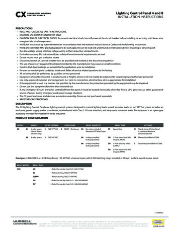
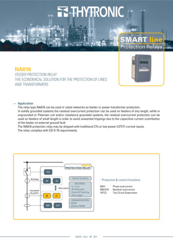
— Example of connection diagram with traditional CT inputs and acquisition of CB states for Data Logger K4A2A1 TRIPA3 UAUXA4A6A5A9A8A7A11A12A10C7S1S2C8IEA13-UAUXA14 IN1CB diagnosticA15(active only withLogger option)A16 IN2Trip Circuitsupervision (TCS)A17 UAUXA18 IN3A19A20(active only withLogger option) UAUXFRONT PANELRS485P1C2C3RS232P2S1S2OUTPUT RELAYSC1P1CTs CURRENT INPUTSK1A 3B2 E1120Ω1A21A22NA016 - Flyer - 09 - 20115
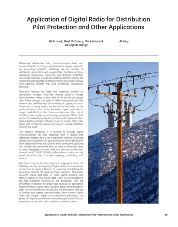
— Example of connection diagram with low power CT inputs and acquisition of CB states for Data Logger UAUXDG52a52b52a52b-UAUXRNA016P2S1S24 6 -IL26 -L350 A100 A200 A400 A800 A4 IL36 -P2L1L24 P1LPCT SettingIL1In 50.1250ALPCTs CURRENT INPUTSP1OUTPUT RELAYSK1K2K3K4A5A4 TRIPA6 UAUXA9A8A7A3A2A1A11A12A10C7S1S2IEC8A13CB diagnosticA15(active only withLogger option)A16 IN2Trip Circuitsupervision (TCS)A17 UAUXA18IN3A19A20(active only withLogger option) UAUXRS232FRONT PANELA21A226NA016 - Flyer - 09 - 2011RS485-UAUXA14 IN1A 3B2 E1120Ω1
DIMENSIONSFRONT VIEWREAR 2L21 2 3 4 5L31 2 3 4 51 2 3 4 550100200400800EX. In 300A(100 1149177A81A3A4A5A7ONF13C1A32A1A2E1E1Traditional CT inputsFLUSH MOUNTING CUTOUTSIDE VIEW75Low power CT inputs75102.5 0.3703032112316115430Traditional CT inputsLow power CT inputsIDENTIFICATION LABELLEDSIn1A5A1A5AIEnUAUX 24-230 Vac/dcIn1A5AIEn 1A5AUAUX 24-230 Vac/dc123451234550-5150N-51NCB OPENCB onal CT inputs - LoggerTraditional CT inputs - no LoggerIn Rated 50.500A/Extended 50.1250AIEn 1A5AUAUX 24-230 Vac/dcIn Rated 50.500A/Extended 50.1250AIEn 1A5AUAUX 24-230 Vac/dc123451234550-5150N-51NCB OPENCB CLOSEDTCSN.4 holes ø 3.550-5150N-51NON: powered device and diagnostics OKSTART: startTRIP: tripNote: the 3, 4 and 5 LEDs are activeonly with Logger optionNA016#xx110NA016#xx010Low power CT inputs - LoggerLow power CT inputs - no LoggerNA016 - Flyer - 09 - 2011Keys(CB open) andare disabled(CB close)7
www.thytronic.itA PERSONALISED SERVICE OF THE PRODUCTION,A RAPID DELIVERY, A COMPETITIVE PRICEAND AN ATTENTIVE EVALUATION OF OURCUSTOMERS NEEDS, HAVE ALL CONTRIBUTEDIN MAKING US ONE OF THE BEST AND MOSTRELIABLE PRODUCERS OF PROTECTIVE RELAYS.FORTY YEARS OF EXPERIENCE HAS MADESTANDARD THESE ADVANTAGES THAT AREGREATLY APPRECIATED BY LARGE COMPANIESTHAT DEAL ON THE INTERNATIONAL MARKET.A HIGHLY QUALIFIED AND MOTIVATED STAFFPERMITS US TO OFFER AN AVANT-GARDEPRODUCT AND SERVICE WHICH MEET ALLSAFETY AND CONTINUITY DEMANDS, VITALIN THE GENERATION OF ELECTRIC POWER. OURCOMPANY PHILOSOPHY HAS HAD A POSITIVEREACTION FROM THE MARKET BY BACKINGOUR COMMITMENT AND HENCE STIMULATINGOUR GROWTH.Headquarter: 20139 Milano - Piazza Mistral, 7 - Tel. 39 02 574 957 01 ra - Fax 39 02 574 037 63Factory: 35127 Padova - Z.I. Sud - Via dell’Artigianato, 48 - Tel. 39 049 894 770 1 ra - Fax 39 049 870 139 nic.it
The relay type NA016 can be used in radial networks as feeder or power transformer protection. In solidly grounded systems the residual overcurrent protection can be used on feeders of any length, while in ungrounded or Petersen coil and/or resistance grounded systems, the residual overcurrent protection can be